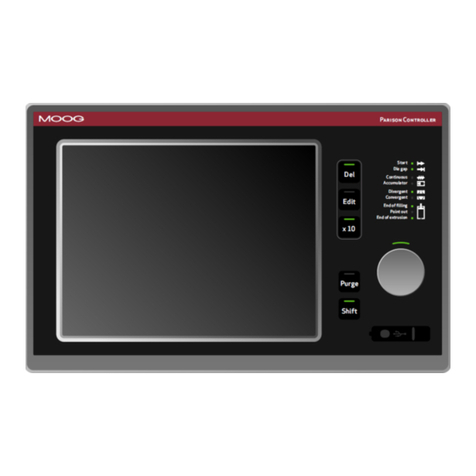
Moog DigiPack III J141-215 Mounting instructions

MRJ06301 Rev. Orig.
DigiPack
Ⅲ
Parison Wall Thickness Controller
J141-215
INSTALLATION,
MAINTENANCE
AND
USER’S MANUAL

© MOOG 2019
This document is subject to MOOG INTELLECTUALAND PROPRIETARY INFORMATION LEGEND . The details are on page II.
I
MRJ06301
RECORD OF CHANGES
Rev.
Page
Description
Prepared
Checked
Approved
Orig.
New Model Release(EOJ20210)
T. Kouda
15, Mar’19
T.Shimizu
15, Mar ‘19
K.Mashino
29,Mar’19

© MOOG 2019
This document is subject to MOOG INTELLECTUALAND PROPRIETARY INFORMATION LEGEND . The details are on page II.
II
MRJ06301
NOTES TO USERS
(1) Description in this manual is subject to change without any obligation on the part of the Manufac-
turer.
(2) Notice would be appreciated if you find any question, omission or error in this manual.
(3) Disassembly, maintenance or repair, other than in accordance with the instruction herein or other
specific written instruction from MOOG will invalidate MOOG’s obligations under its warranty.
Refer to MOOG warranty for complete previsions thereof.
SAFETY INSTRUCTION
Description in this manual is essential to the safety of life and property, therefore, before operating
this equipment, you should first thoroughly read this manual, and this manual should be kept in ac-
cessible for when you have any questions.
WARNING
This symbol with the word “WARNING” is used to call attention to safety instructions
concerning a potential hazard to people. Failure to comply with these safety instructions
can result in serious damage to health and can even prove fatal in extreme cases.
CAUTION
This symbol with the word “CAUTION” is used to call attention to instructions concerning
potential damage to the equipment or to the system as a whole.
NOTE
Notes contain useful information to the operator when starting up and operating the equip-
ment or system.
MOOG JAPAN LTD.
1-8-37 NishiShindo, Hiratsuka, Japan 254-0019
Tel:+81-463-55-7141 Fax:+81-463-54-4709
MOOG INTELLECTUAL AND PROPRIETARY INFORMATION LEGEND
This technical Document contains information that is proprietary to, and is the express property of Moog Inc., or Moog Inc. subsidiaries
except as expressly granted by contract or by operation of law and is restricted to use by only Moog employees and other persons
authorized in writing by Moog or as expressly granted by contract or by operation of law. No portion of this Data/Drawing/Document
shall be reproduced or disclosed or copied or furnished in whole or in part to others or used by others for any purpose whatsoever
except as specifically authorized in writing by Moog Inc.

© MOOG 2019
This document is subject to MOOG INTELLECTUALAND PROPRIETARY INFORMATION LEGEND . The details are on page II.
III
MRJ06301
About EMC Standard
1. Safety standard
Notes to certified of EC directive
J141-215 DigiPackⅢis a device incorporated in customer's equipment (blow molding machine) and we
are conductingEMC test against ECDirective within the scope of embedded equipment, but the J141-215
DigiPackⅢuse by itself is not compatible with the EC Directive.
When customer completes the equipment with J141-215 and use it within Europe or shipment to the area
within European region as the final product, please be sure to check certified of EC Directive by customer
self.
Applicable directive and relative standard.
J141-215 is conducting the EMC test conforming to the EC directive below. It shows directives and related
standards.
EC Directive: EMC Directive 2014/30/EU
Relative Standard:
EN 61000-6-2:2005
IEC61000-4-2~6
Electromagnetic compatibility (EMC) - Part 6-2: Generic standards
- Immunity for industrial environments
EN61000-6-4:2007+A1:2011
Industrial, scientific and medical equipment - Radio-frequency dis-
turbance characteristics - Limits and methods of measurement
2. Measures EMC
In order to applicable EMC directive, please takes suitable measure against EMC with a customer's blow
molding machine.
And also, when include J141-215 in apparatus and it is used, please considerwire connection and ground-
ing.
The cable used for each wire connection recommends use of a shielded cable.
A shielded cable should be connected to the terminal of J141-215, and the length of skin wire processing
should be less than 100 mm.

© MOOG 2019
This document is subject to MOOG INTELLECTUALAND PROPRIETARY INFORMATION LEGEND . The details are on page II.
IV
MRJ06301
TABLE OF CONTENTS
1. DigiPackⅢManual, Installation and Maintenance..............................................................................1
1-1. CHANGES FROM J141-214A.........................................................................................................1
1-2. INTRODUCTION..............................................................................................................................2
1-2-1. GENERAL DESCRIPTION.............................................................................................. 2
1-2-2. WHO CAN INSTALL THE DigiPackⅢ............................................................................. 5
1-2-3. INSTALLATION TIME ..................................................................................................... 6
1-2-4. SOFTWARE UPDATE .................................................................................................... 6
1-2-5. BACKUP BATTERY........................................................................................................ 7
1-2-6. SCREEN DISPLAY PROTECTION (password)............................................................... 7
1-2-7. DATATRANSFER FROM DigiPackⅡ............................................................................. 7
1-3. DigiPackⅢSPECIFICATION..........................................................................................................8
1-4. CHECK LIST....................................................................................................................................9
1-4-1. INSTALLATION CHECK LIST......................................................................................... 9
1-5. MECHANICAL INSTALLATION .....................................................................................................10
1-5-1. GENERAL .....................................................................................................................10
1-5-2. TOOLING ADJUSTMENT..............................................................................................11
1-5-3. MOOG DIE GAP TOOLINGACTUATORS.....................................................................12
1-5-4. CYLINDER INSTALLATION...........................................................................................12
1-5-5. CUSTOMER SUPPLIED CYLINDER REQUIREMENTS................................................13
1-5-6. TOOLING ADJUSTMENT..............................................................................................14
1-5-7. ACCUMULATOR POSITION MEASUREMENT .............................................................14
1-5-8. THE IMPORTANCE OF FILTRATION ............................................................................15
1-5-9. FILTER INSTALLATION.................................................................................................15
1-5-10. HYDRAULIC POWER SUPPLY...................................................................................16
1-5-11. HYDRAULIC POWER SUPPLY START UP INSTRUCTIONS......................................16
1-5-12. CONTAMINATION CONTROL.....................................................................................17
1-6. ELECTRICAL INSTALLATION.......................................................................................................18
1-6-1. GENERAL .....................................................................................................................18
1-6-2. REAR CONNECTOR.....................................................................................................18
1-6-3. TB-1, TB-2 WIRING.......................................................................................................19
1-6-4. COMMUNICATION AND SSI SNSOR WIRING..............................................................19
1-6-5. TB-2 I/O CIRCUITRY.....................................................................................................25
1-6-6. TB-3: POWER SUPPLY.................................................................................................26
1-6-7. NOISE AND GROUND ISOLATION...............................................................................26

© MOOG 2019
This document is subject to MOOG INTELLECTUALAND PROPRIETARY INFORMATION LEGEND . The details are on page II.
V
MRJ06301
1-7. CALIBRATION OF TOUCH SCREEN ...........................................................................................29
1-8. DigiPackⅢfront panel ..................................................................................................................30
1-9. TOOLING SYSTEM SETUP..........................................................................................................32
1-9-1. GENERAL OF SETUP...................................................................................................32
1-9-2. MACHINE SETTING......................................................................................................32
1-9-3. SET UP PROCEDURE..................................................................................................35
2. DigiPackⅢManual, User operation ..................................................................................................43
2-1. INTRODUCTION............................................................................................................................43
2-2. PARISON CONTROL.....................................................................................................................44
2-2-1. HISTORY.......................................................................................................................44
2-2-2. PARISON PROGRAMMING BENEFITS........................................................................44
2-2-3. CONTINUOUS EXTRUSION MACHINES .....................................................................44
2-2-4. ACCUMULATOR MACHINES........................................................................................44
2-2-5. PARISON PROGRAMMING BENEFITS........................................................................45
2-2-6. WITH ACCUMULATOR BLOW MOLDING MACHINES .................................................46
2-2-7. WITH CONTINUOUS BLOW MOLDING MACHINES ....................................................46
2-2-8. PARISON MOLD ALIGNMENT ......................................................................................47
2-3. MAN MACHINE INTERFACE........................................................................................................48
2-3-1. OPERATOR CONTROL.................................................................................................48
2-3-2. INPUT FUNCTION.........................................................................................................48
2-3-3. FUNCTIONS..................................................................................................................51
2-3-4. STATE MONITORING AREA .........................................................................................51
2-3-5. EDIT AREA....................................................................................................................52
2-4. SCREENS OF EDITAREA............................................................................................................53
2-4-1. EDITING METHOD........................................................................................................53
2-4-2. F1: Profile Mode ............................................................................................................54
2-4-3. F2: Marker Mode ...........................................................................................................59
2-4-4. F3: File Mode.................................................................................................................61
2-4-5. F4: Monitor Mode...........................................................................................................65
2-4-6. F5: Data Display Mode ..................................................................................................66
2-4-7. SHIFT→F1: Set Up Mode..............................................................................................67
2-4-8. SHIFT→F2: Analog monitor...........................................................................................67
2-4-9. SHIFT→F3: File delete and Backup/Restore .................................................................68
2-4-10. SHIFT→F4: Machine Setup.........................................................................................69
2-4-11. SHIFT→F5: Communication Mode...............................................................................70
2-5. COMMUNICATION PROTOCOL...................................................................................................71
2-5-1. EtherNET COMMUNICATION SPECIFICATION............................................................71

© MOOG 2019
This document is subject to MOOG INTELLECTUALAND PROPRIETARY INFORMATION LEGEND . The details are on page II.
VI
MRJ06301
2-5-2. PROFILE.......................................................................................................................71
2-5-3. WAVE ............................................................................................................................73
2-5-4. MONITOR......................................................................................................................73
2-5-5. INFORMATION DATA....................................................................................................73
2-5-6. INTERFACE CONTROL ................................................................................................74
2-5-7. OTHER..........................................................................................................................76
2-5-8. ERROR CODE ..............................................................................................................76
2-5-9. ADC/DAC CHANNEL.....................................................................................................76
2-6. PROFILE DATA LIST.....................................................................................................................77
2-7. SETTING UP..................................................................................................................................78
2-7-1. OBJECTIVE...................................................................................................................78
2-7-2. DIE GAP TOOLING SETUP...........................................................................................78
2-7-3. PRELIMINARY SET UP.................................................................................................79
2-7-4. INITIAL TRIALS.............................................................................................................80
Reference Drawings
CC70353 ---------- Installation
CC70355---------- Customer Wiring

© MOOG 2019
This document is subject to MOOG INTELLECTUALAND PROPRIETARY INFORMATION LEGEND . The details are on page II.
VII
MRJ06301
Table of Figure
Figure 1-1 DigiPackⅢappearance - - - - - - Page 2
Figure 1-2 Basic Continuous Blow Molding Machine Control Diagram- - - Page 3
Figure 1-3 Basic Accumulator Machine Control Diagram- - - - Page 4
Figure 1-4 Start up Display- - - - - - - Page 6
Figure 1-5 Die Gap Tooling Actuator Installation - - - - Page 10
Figure 1-6 Die Gap Tooling Actuator- - - - - - Page 10
Figure 1-7 Actuator –Die Gap Tooling Mechanical Adjustment - - - Page 11
Figure 1-8 Tooling Adjustment Mechanism - - - - - Page 11
Figure 1-9 Typical Cylinder Installation - - - - - Page 12
Figure 1-10 G631-XXX Servovalve - - - - - - Page 13
Figure 1-11 Typical Linear Potentiometer - - - - - Page 14
Figure 1-12 LWHxxx Potentiometer Installation- - - - - Page 14
Figure 1-13 High Pressure Filter - - - - - - Page 15
Figure 1-14 Hydraulic Power Supply - - - - - Page 16
Figure 1-15 Flow Pressure Filter - - - - - - Page 17
Figure 1-16 REAR CONNECTOR - - - - - - Page 18
Figure 1-17 DigiPackⅢInstallation Drawing - - - - - Page 20
Figure 1-18 ServoValve and Transducer Phasing- - - - - Page 21
Figure 1-19 TB-1 Connections - - - - - - Page 21
Figure 1-20 TB-1 Functions - - - - - - Page 22
Figure 1-21 TB-2 Connection - - - - - - Page 23
Figure 1-22 TB-2 Connection - - - - - - Page 23
Figure 1-23 TB-2 Functions - - - - - - Page 24
Figure 1-24 Input use external Power supply - - - - - Page 25
Figure 1-25 Input use internal Power supply - - - - - Page 25
Figure 1-26 Output use external Power supply - - - - Page 25
Figure 1-27 Output use internal Power supply- - - - - Page 25
Figure 1-28 Power supply Connections - - - - - Page 26
Figure 1-29 Accumulator Machine Timing chart - - - - Page 27
Figure 1-30 Continuous Machine Timing chart - - - - Page 28
Figure 1-31 Touch screen Calibration - - - - - Page 29
Figure 1-32 Touch screen calibration display - - - - - Page 29
Figure 1-33 DigiPackⅢFlont panel - - - - - - Page 30
Figure 1-34 Machine setup display (SHIFT→F4) - - - - Page 33
Figure 1-35 Machine setting Functions - - - - - Page 33
Figure 1-36 Example of profile points change- - - - - Page 34
Figure 1-37 Setup screen - - - - - - - Page 35
Figure 1-38 Die Converge/Diverge Setup- - - - - - Page 35
Figure 1-39 Die Gap Setup- - - - - - - Page 36
Figure 1-40 DCDT Noise Filter - - - - - - Page 36
Figure 1-41 Die Gap Span Setting - - - - - - Page 37
Figure 1-42 Back - - - - - - - - Page 38
Figure 1-43 Gain select - - - - - - - Page 39
Figure 1-44 Gain setting - - - - - - - Page 39
Figure 1-45 Accumulator Setup - - - - - - Page 40
Figure 1-46 EMPTYAccumulator Set Up - - - - - Page 40
Figure 1-47 FULL Accumulator Set Up - - - - - Page 41
Figure 1-48 Extrusion Fixed- - - - - - - Page 41
Figure 1-49 Filling Fixed - - - - - - - Page 41
Figure 1-50 Accumulator setting (Back) - - - - - Page 42


© MOOG 2019
This document is subject to MOOG INTELLECTUALAND PROPRIETARY INFORMATION LEGEND . The details are on page II.
VIII
MRJ06301
Figure 2-1 DigiPackⅢappearance - - - - - - Page 43
Figure 2-2 Section of an Un-programmed Parison and the Resulting Container Walls Page 45
Figure 2-3 Section of a Programmed Parison and the Resulting Container Walls - Page 45
Figure 2-4 Poor Vertical Alignment Between the Parison and the Mold - - Page 47
Figure 2-5 Good Vertical Alignment Between the Parison and the Mold. - - Page 47
Figure 2-6 DigiPackⅢFront panel - - - - - - Page 48
Figure 2-7 Ten key on the screen (1) - - - - - Page 49
Figure 2-8 Ten key on the screen (2) - - - - - Page 49
Figure 2-9 Status indicator - - - - - - - Page 52
Figure 2-10 F1: Profile mode Screen - - - - - Page 53
Figure 2-11 Profile Mode Screen - - - - - - Page 54
Figure 2-12 0%Weight Change - - - - - - Page 56
Figure 2-13 (-)23.3% Weight Change - - - - - Page 56
Figure 2-14 0% Range H - - - - - - - Page 57
Figure 2-15 (+)25.0% Range H Change - - - - - Page 57
Figure 2-16 0% Range L - - - - - - - Page 58
Figure 2-17 (-)20.0% Range L - - - - - - Page 58
Figure 2-18 Marker Mode Screen - - - - - - Page 59
Figure 2-19 Slope Timing - - - - - - - Page 60
Figure 2-20 File Mode Selection Screen - - - - - Page 61
Figure 2-21 Select SAVE - - - - - - - Page 61
Figure 2-22 File Description Data-Page 1 - - - - - Page 62
Figure 2-23 File Description Data-Page 2 - - - - - Page 62
Figure 2-24 File Description Data-Page 3 - - - - - Page 62
Figure 2-25 Edit File name - - - - - - - Page 63
Figure 2-26 Change File Number - - - - - - Page 63
Figure 2-27 Initial Load Screen - - - - - - Page 64
Figure 2-28 File Load - - - - - - - Page 64
Figure 2-29 F4: Monito screen - - - - - - Page 65
Figure 2-30 Data Display Screen A - - - - - - Page 66
Figure 2-31 Data Display Screen B - - - - - - Page 66
Figure 2-32 Data Display Screen C - - - - - - Page 66
Figure 2-33 [SHIFT]→[F1]: Setup Screen - - - - - Page 67
Figure 2-34 [SHIFT]→[F2]: Analog Monitor Screen- - - - - Page 67
Figure 2-35 [SHIFT]→[F3]: File delete and Backup - - - - Page 68
Figure 2-36 File Delete - - - - - - - Page 69
Figure 2-37 [SHIFT]→[F4]: Machine Setup Screen - - - - Page 69
Figure 2-38 [SHIFT]→[F5]: Communication Mode Screen - - - Page 70

© MOOG 2019
This document is subject to MOOG INTELLECTUALAND PROPRIETARY INFORMATION LEGEND . The details are on page II.
1
MRJ06301
1. DigiPackⅢManual, Installation and Maintenance
1-1. CHANGES FROM J141-214A
The basic specifications of DigiPackⅢ(J141-215) are equivalent to conventional J141-214A.
There are the following major differences.
Changed from currnt VGA(480 x 640) to WXGA(1200 x 800) size
In addition, with touch screen conversion, operation by the conventional push button switch and
display by the LED are abolished, and it is changed to operation/display on the screen. (Excluding
rotary knob and power supply confirmation LED)
Considering availability, change the external storage device to USB memory. (It is not attached to
controller)
The following USB memory has been tested for operation. The operation can not be guaranteed
with USB memory other than these model numbers. We recommend that you select the same
model number as below when purchasing.
-HTU3A 16GBK
In addition, other than the above, you can refer to the list of USB memories being used without
problems by customers at the following URL:
https://www.moog.co.jp/products/controllers-software/blow-molding-controllers/digipack3.html
-tightened, and the terminal block was made detachable.
Mounting screw size is M3.5. Please use crimp terminal matching it.
Also, since the terminal block is removable, rewiring is unnecessary when replacing the controller.
Name change: DI 10 Servo OFF → Emergency. This signal is normally(under control) OFF, and
if input is ON, turns OFF the servo output. For details, refer to Figure 1-23 TB-2 Functions .
Signal addition: DI 11 temperature up completion. This signal is normally(under control) OFF, and
if input is ON, turns OFF the servo output. (Please turn ON when the resin is sufficiently warmed
up and it becomes operable.) Please refer to Figure 1-23 TB-2 Functions for details.
serial communication function
For other details, please check this manual in detail.

© MOOG 2019
This document is subject to MOOG INTELLECTUALAND PROPRIETARY INFORMATION LEGEND . The details are on page II.
2
MRJ06301
1-2. INTRODUCTION
288.00 mm
LCD Touch screen 10.1 (WVGA)
青色画面時 (RGB: 183.221.232)
DigiPackⅢ
Parison Controller
MOOG
0% 25% 50% 75% 100%
100
90
80
70
60
50
40
30
20
10
1
File Name:1234567890123456
Point No.
Die gap
Delay
Auto cycle
72
5.0
1.5
ON
%
sec
Data
Weight
Range H
Range L
* 79.0
0.0
0.0
0.0
%
%
%
%
5
6
Start
Die gap
Continuous
Accumulator
Divergent
Convergent
End of filling
Point out
End of
extrusion
F1 : Profile
F2 : Marker
F3 : File
F4 : Monitor
F5 : Data
Cursor
DEL Shift
X10 Set
2018/1/23 13:35:45
Cycle time 10.0 100% = 25.40 m
m
sec
Figure 1-1 DigiPackⅢappearance
1-2-1. GENERAL DESCRIPTION
The J141-215 DigiPackⅢis a user friendly, high performance 200 Point Digital Blow Molding Parison
Wall Thickness controller producing lighter, stronger containers at increased production rates.
A properly installed and intelligently used system will deliver higher operating efficiency from your blow
molding machine as a result of faster molding cycles, shorter change over times and reduced scrap.
The DigiPackⅢadjusts the parison wall thickness by controlling the core position with the core actuator.
The core position can be finely set up to 200 points maximum.
For an accumulator type blow molding machine, set the target core position with reference to the accumu-
lator position. For a continuous blow molding machine, set the target core position based on time.
The core position control system with the above setting consists of four main components: DigiPackⅢ
controller, servo valve, actuator for core and feedback detector for accumulator. The function of each
component is as follows.
Operator using DigiPackⅢto set the core position (core die gap opening / closing amount) required
to obtain a product with the desired wall thickness (usually constant wall thickness). In addition, it
outputs a flow (spool position) command to the servo valve so that the core follows the set core
position.
DigiPackⅢalso functions as a digital interface with the PLC controller of the blow molding machine
and provides information such as the end of the program and the point status of sequential programs.
The servo valve adjusts the flow rate to the core actuator according to the flow (spool position) com-
mand from DigiPackⅢ.
The actuator for the core, the core is fixed to the rod, and the rod (core) moves according to the flow
rate adjusted by the servo valve. Moving the core changes the gap through which the parison passes
and controls the wall thickness of the parison.

© MOOG 2019
This document is subject to MOOG INTELLECTUALAND PROPRIETARY INFORMATION LEGEND . The details are on page II.
3
MRJ06301
Accumulator feedback detector is used for accumulator type blow molding machine. The DigiPackⅢ
changes the target core position while monitoring the signal from this detector.
1.2.1.1. Continuous blow molding machines
Figure 1-2 Basic Continuous Blow Molding Machine Control Diagram
When used with continuous blow molding machines, the DigiPackⅢcontrols the parison wall thickness
relativetothemachinecycletime. Themachinecyclestartswhenthestartsignalisinput(whentheparison
cutting knife disconnects the parison). The cycle time can be determined by the following.
a) Fixed cycle time set by the operator (when [Auto cycle] is OFF)
b) Automatic cycle time set by repeatedly measuring the time between start signals (when [AUTO CY-
CLE] is ON)
When using the fixed cycle time of a), it is necessary for the machine operation time to be negligible for
reasons such as multiple die interlocking, or It is a premise that it is a machine that performs machine
functions such as closing and moving molds within the cycle time
The shape of the parison wall profile is set digitally by the operator. The size of the die gap, measured by
a die gap position transducer, is compared with the operators commanded position as set on the DigiPack
Ⅲdisplay.
The error between the operators set position and the actual position causes the servovalve to flow oil to
the actuator to reduce the position error to a very small value. This feedback process ensures that the
actual die gap follows the commanded die gap very accurately.
With a continuous blow molding machine, DigiPackⅢoperates / processes as follows.
①The operator sets the core position (core die gap opening / closing amount) necessary to obtain the
desired wall thickness (usually constant wall thickness) product on the DigiPackⅢcontroller panel.
②When the start signal switches from OFF to ON, DigiPackⅢcontrols the servo valve so that the core
follows the set position according to the cycle time.
③The servo valve adjusts the flow rate to the core actuator according to the (flow rate) command from
DigiPackⅢ.
Hydraulics
Die Gap
Tooling
Actuator
PLC Controller
Servovalve
Actuator
DCDT
Core Position
Parison Cutoff Knife

© MOOG 2019
This document is subject to MOOG INTELLECTUALAND PROPRIETARY INFORMATION LEGEND . The details are on page II.
4
MRJ06301
④By controlling the actuator for the core, control the thickness of the parison at the core die gap portion.
⑤During ②to ④, DigiPackⅢfunctions as a digital interface with the PLC of the blow molding machine
and provides information such as the end of the program and the point status of the program sequen-
tially.
1.2.1.2. Accumurator type molding machines
When used with accumulator machines, the DigiPackⅢcontrols the parison wall thickness relative to the
accumulator position as the plastic is being extruded.
As the total quantity or volume of plastic extruded isproportional to the accumulator position, then it follows
that the resulting parison wall thickness at any given point on the length of the container must be related
to the accumulator position. Given that the physical properties of the plastic and its temperature are con-
stant from container to container, then each container’s weight and strength will be consistent.
Figure 1-3 Basic Accumulator Machine Control Diagram
A potentiometer measures the accumulator position and controls the vertical axis of the program display.
The operator can also set the accumulator operating stroke, shot size, and accumulator injection comple-
tion position (cushion). In addition, DigiPackⅢalso provides interface signals to the machine's PLC for
these functions.After that, the operation of the accumulator is controlled by the PLC.
With an accumulator type blow molding machine, DigiPackⅢoperates / processes as follows.
①The operator sets the core position (core die gap opening / closing amount) necessary to obtain the
desired wall thickness (usually constant wall thickness) product on the DigiPackⅢcontroller panel.
②When the start signal switches from OFF to ON, the DigiPackⅢcontrols the servo valve so that the
core follows the set position according to the position of the accumulator.
③The servo valve adjusts the flow rate to the core actuator according to the (flow rate) command from
DigiPackⅢ.
④By controlling the actuator for the core, control the thickness of the parison at the core die gap portion.
Hydraulics
Die Gap
Tooling
Actuator
PLC Controller
Servovalve
Actuator
DCDT
Position
Accumulator Push Cylinder
Accumulator
Position

© MOOG 2019
This document is subject to MOOG INTELLECTUALAND PROPRIETARY INFORMATION LEGEND . The details are on page II.
5
MRJ06301
⑤During ②to ④, DigiPackⅢfunctions as a digital interface with the PLC of the blow molding machine
and provides information such as the end of the program and the point status of the program se-
quentially.
Successful performance of the DigiPackⅢdepends a great deal upon how well it is installed on the
machine. By following the instructions contained idatan this manual it will be possible to easily install this
system and obtain many years of trouble free operation.
1-2-2. WHO CAN INSTALL THE DigiPackⅢ
The installation of the DigiPackⅢcontrol system requires the installer to be familiar with electrical wiring,
hydraulic plumbing and basic metal working. The calibration and start up of the finished system requires
some understanding of the blow molding process and use of test instruments such as a digital voltmeter.
The plumbing, wiring and bracketry should not be difficult. Most molding shop maintenance men who are
familiar with blow molding machines will have little difficulty with the help of this manual.
The system can be satisfactorily calibrated to the machine and started up without assistance or special
equipment by following the instructions in this manual.

© MOOG 2019
This document is subject to MOOG INTELLECTUALAND PROPRIETARY INFORMATION LEGEND . The details are on page II.
6
MRJ06301
1-2-3. INSTALLATION TIME
The time to install a DigiPackⅢvaries with the type and size of machine, mechanical constraints such
as the location of water lines andauxiliary equipment and the ability of the mechanic doing the installation.
Our experience has shown that typical maintenance men will require about 20 to 30 man hours. Smaller
machines will require less time.
Of this time, the actual machine shut down time can be held to 6 hours or less.
1-2-4. SOFTWARE UPDATE
The software of this controller may be updated if a bug is found or the function is improved. Please check
the software update status (latest version) from the MOOG website below. Also you can download the
update file "DIGIPK3.FMW" from the website. How to update Please refer to the following description.
Update Process
1. Prepare the USB memory and turn off the power of DigiPackⅢ.
2. Save the "DIGIPK3.FWM" file to the USB memory using the computer.
3. Insert the USB memory into the DigiPackⅢand turn ON the DigiPackⅢ.
4. Turn the rotary knob clockwise while turning on the power.
5. When "Updating firmware ..." appears on the display, the update process is in progress.
※It takes about 30 seconds to update. If "Failed" is displayed on the screen, or if nothing happens
and screen changed to the startup screen, the upgrade fails. Please try again from process 1. If
"Failed" is inevitably displayed and the upgrade is not successful, there is a possibility that the file
is broken. Please download "DIGIPK3.FWM" again and try update again.
6. Then check the software version in the startup display (Figure 1-4).
7. Turn off the power and remove the USB memory.
Figure 1-4 Start up Display
USB memory is not included with DigiPackⅢ. Refer to section 1-1. for recommended USB.
"DIGIPK3.FWM" can download the latest version from the MOOG website
https://www.moog.co.jp/products/controllers-software/blow-molding-controllers/digipack3.html
USB memory
Save
DIGIPK3.FMW
Software version

© MOOG 2019
This document is subject to MOOG INTELLECTUALAND PROPRIETARY INFORMATION LEGEND . The details are on page II.
7
MRJ06301
1-2-5. BACKUP BATTERY
Since backup of an internal clock is using the ultra capacitor, there is no necessity for exchange.
Backup time is about three weeks.
A time display may be [----.--.-- --:--] when not turning on electricity the time of the power activation after
purchase, and for a long period of time.
In such a case, please set up the right time on F2 screen. (Reference 2-4-3. )
1-2-6. SCREEN DISPLAY PROTECTION (password)
The DigiPackⅢhas two types of screen configurations that the normal operation screen (F1 to F5) and
the setting screen (SHIFT → F1 to F5) for making various settings. Each screen can be distinguished by
the color of the background. The background color of the normal operation screen is light blue " "
The background color of the setting screen is yellow" ". In this controller, the transition to the setting
screen is limited by the password. When entering the setting screen, entering a password enables you to
migrate.
* Once you enter the password, it is not necessary to enter the password until you restart the controller.
Also, if password function is unnecessary, it is possible to invalidate password from SHIFT → F4 screen.
See 1.9.2.1
Password: 6009 (Password is fixed and can not be changed)
Password input
After activating the controller, the password entry screen will be displayed when entering to the setup
screen by first pressing “SHIFT” and then pressed Fx key. Once you enter 4-digit password, you will be
able to switch to the setup screen without entering again the password. This will be retained until you
restart DigiPackⅢ.
In addition, this password can be enabled / disabled on the machine setting screen (SHIFT→ F4) . Refer
to Section 1.9.2.1 Machine Settings for details.
This level change does not indicate any notice on display. Please check the level is correctly
changes or not by press SHIFT→F1, if the level “Low” should not goes to setup display
1-2-7. DATA TRANSFER FROM DigiPackⅡ
The saving data of DigiPackⅡcan be transferred to DigiPackⅢdue to following process.
With the DIgiPackⅡsave the parameters file to SD Card and copy it to USB by using PC. Then, load
parameter file from USB to DigiPackⅢ. (Refer to 2-4-4. for save/load description)
NOTE: New parameter like PURGE/TOOLING is not include.

© MOOG 2019
This document is subject to MOOG INTELLECTUALAND PROPRIETARY INFORMATION LEGEND . The details are on page II.
8
MRJ06301
1-3. DigiPackⅢSPECIFICATION
Model Number:
J141-215 DigiPackⅢ.
Function:
Max 200 points Single head blow molding Parison programmer
Application:
Accumulator Based or Continuous Extrusion Blow Molding Machines
can be selected.
Profile Points:
10 to 200,Custom points. And Straight or Spline interpolation can be
selected.
Tooling Type:
Divergent or convergent die gap tooling types can be selected.
Tooling Position Control:
Digital closed loop servo system with a 1m sec update time.
Tooling Position Monitor:
From Tooling Position Actuator’s DCDT 10 VDC.
Accumulator Position Monitor:
From Accumulator Potentiometer 0 to 10 VDC FS.
Programming Inputs:
By Rotaly knob and touch panel switches.
Display:
Color Display (LCD). 10.1 inch(WXGA) touch screen.
English/Japanese/Chinese language selected by Parameter at Setup
screen.
Memory:
100 program profile patterns can be stored in a Flash RAM. And can
be stored in USB memory.
※Supports standard USB memory, up to 32G. (Refer to 1-1. )
※Data format: FAT32
Point Marker:
A marker output signal can be set maximum 10 program point.
Other Functions:
Shot Size, Delay, Cushion (for accumulator machines only), die gap,
data saving, profile curve adjustment (Weight and Range H/L), adjust-
ment of the tooling actuator stroke and the accumulator position trans-
ducer, backup for the system timer(by capacitor).
Output to Servovalve:
MFB type: ± 10, 20, 50, 100 mA or EFB type: ± 10 VDC
Servovalve Monitor:
± 100% Spool Stroke equals 4-20mA
I/O for Accumulator:
0 to 10 VDC transducer output and 10 V DC transducer excitation.
I/O for Tooling Position:
± 10 VDC DCDT output and ± 10 V DC DCDT excitation.
Common External Input:
Photo Coupler Isolated
Customer Supplied 15 to 24 Vdc @ 10 mA /Channel
24 VDC External Outputs:
Photo MOS Relay
Customer Supplied 15 to 24 Vdc @
100mA /Channel Max.
Accumulator type: End of Extrusion/Filling Relay Contacts:
250Vac @ 1 A/channel MAX.
Communication:
Data transfer with host computer by RS422 and Ethernet
Power Requirements:
24 VDC 0.5Amin (MAX 3.0Adepend on Servovalve Power required)
No ripple requirement : Max +-10 %
Temperature/Humidity:
0 to 45ºC within 85% relative humidity
IP rating
Front side = IP20, Rear side = IP30
Dimensions:
288 (W) x 240 (H) x 55 (D) mm (not include terminal)
Weight:
3.6 kg

© MOOG 2019
This document is subject to MOOG INTELLECTUALAND PROPRIETARY INFORMATION LEGEND . The details are on page II.
9
MRJ06301
1-4. CHECK LIST
*The instructions in this section are general installation procedures.
1-4-1. INSTALLATION CHECK LIST
Order parts for installation
Identify component mounting locations and procure the necessary mounting brackets
Install the DigiPackⅢunit in the blow molding machine or optional enclosure
Mount tooling servoactuator to machine
or Mount servovalve manifold and
or Mount DCDT to tooling actuator
Mount servo actuator pressure filter
Install hydraulic power supply
Install main system filter
Make hydraulic pressure and return connections and flush the hydraulic system,
Mount accumulator position transducer, if required
Install conduit and pull cables for the tooling servoactuator, transducers, filter differential pressure switch
and interface between the DigiPackⅢcontrol panel and the machine PLC
Check the wiring
Calibrate transducers
Set up the control loop
Connect the actuator to the die gap tooling and adjust the die gap end points.

© MOOG 2019
This document is subject to MOOG INTELLECTUALAND PROPRIETARY INFORMATION LEGEND . The details are on page II.
10
MRJ06301
1-5. MECHANICAL INSTALLATION
*The instructions in this section are general installation procedures.
1-5-1. GENERAL
Mounting provisions for the tooling servoactuator
should include a stable mounting platform for the
tooling actuator, a filter location which allows the filter
element to be readily replaced and mechanical pro-
visions allowing simple adjustment of the mechanical
relationship between the actuator and the die gap.
Figure 1-5 shows such as a well planned installation.
Atooling servoactuator provides a long lived solution
to the problems caused by high temperatures and
force levels. Low friction seals and strong bearings
insure long term and good tooling die gap positioning
performance. A built in position transducer provides
mechanical isolation from shocks and climbing feet.
Adirectly manifold servovalve is tightlycoupled to the
actuator. Figure1-6 illustrates a packaged tooling ac-
tuator with provisions for pre-blow air.
Figure 1-5 shows a typical tooling actuator installa-
tion. Aservovalve (upper right) is directly mounted on
a manifold, which in turn is attached to a tooling ac-
tuator. Directly below is a DCDT position transducer
measuring the actuator rod and die gap tooling mo-
tion. In addition, a high pressure filter mounted di-
rectly on the manifold provides clean oil to the servo-
valve. Tooling adjustment provisions are also shown.
Figure 1-5 Die Gap Tooling Actuator Installa-
tion
Figure 1-6 Die Gap Tooling Actuator
Filter
Servovalve
DCDT
Tooling Actuator

© MOOG 2019
This document is subject to MOOG INTELLECTUALAND PROPRIETARY INFORMATION LEGEND . The details are on page II.
11
MRJ06301
Figure 1-7 Actuator –Die Gap Tooling Mechanical Adjustment
1-5-2. TOOLING ADJUSTMENT
When a mold change is made, it is often necessary to
change the die gap tooling assembly. Therefore the actu-
ator installation must provide for simple adjustment of the
die gap tooling position relative to the actuator position.
Figure 1-7 shows two possible methods of adjusting the
positional relationship between the tooling actuator and
the die gap tooling’s closed position. Tooling motion stops
may be required to limit the forces on the die gap tooling
when the die and mandrel touch. Figure 1-8 is a typical
installation.
Some actuators with an anti-rotation fea-
ture require the nut torque loads on the
anti-rotation device to be limited by ab-
sorbing the tightening torque with a
wrench on the actuator rod flats
Tooling stops are required to insure a die gap that cannot close on a continuous molding machine. An
inadvertent closure of the die gap could cause very high pressures in the extruder barrel and extrusion
head and result in their damage and/or failure.
The above comments must be considered for the proper installation of either a Moog supplied die gap
tooling actuator or a customer supplied actuator.
Figure 1-8 Tooling Adjustment Mechanism
Die Gap
Adjust-
ment
Collar
Lock
Nuts
Table of contents
Other Moog Controllers manuals

Moog
Moog IMI220-145D001 User manual

Moog
Moog Silencer series User manual

Moog
Moog MSD Servo Drive single axis system User manual

Moog
Moog D085-172 Quick start guide

Moog
Moog MDS Servo Drive User manual

Moog
Moog DS2110 User manual

Moog
Moog Silencer Series User manual

Moog
Moog DigiPack 2 Mounting instructions