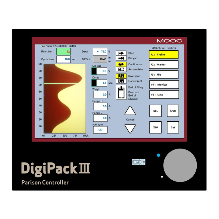
Moog DigiPack 2 Mounting instructions

MRJ04410 Rev. A.
DigiPack Ⅱ
Parison Wall Thickness Controller
J141-214A
INSTALLATION,
MAINTENANCE
AND
USER’S MANUAL

© MOOG 2010
This document is subject to MOOG INTELLECTUALAND PROPRIETARY INFORMATION LEGEND . The details are on page II.
II MRJ04410
RECORD OF CHANGES
Rev. Page Description Prepared Checked Approved
Orig.
New Model Release T. Kouda
13, Jan’12
R.Nagasaki
18, Jan’12
M. Shiga
18, Jan’12
A 71-75 RS422 Communications pro-
tocol correction
・ When write the profile sys-
tem communication com-
mand (PX), automatically
write to a flash. (Delete PF
Command)
・ When BCC of a communi-
cation command is "**", a
check is skipped and it
answers as normal.(Change
of explanation of the BCC
command)
T. Kouda
(2, Mar’12)
R. Nagasaki
( 3, Mar’12)
M. Shiga
( 3, Mar’12)

© MOOG 2010
This document is subject to MOOG INTELLECTUALAND PROPRIETARY INFORMATION LEGEND . The details are on page II.
III MRJ04410
NOTES TO USERS
(1) Description in this manual is subject to change without any obligation on the part of the Manu-
facturer.
(2) Notice would be appreciated if you find any question, omission or error in this manual.
(3) Disassembly, maintenance or repair, other than in accordance with the instruction herein or other
specific written instruction from MOOG will invalidate MOOG’s obligations under its warranty.
Refer to MOOG warranty for complete previsions thereof.
SAFETY INSTRUCTION
Description in this manual is essential to the safety of life and property, therefore, before operating
this equipment, you should first thoroughly read this manual, and this manual should be kept in ac-
cessible for when you have any questions.
WARNING
This symbol with the word “WARNING” is used to call attention to safety instructions
concerning a potential hazard to people. Failure to comply with these safety instructions
can result in serious damage to health and can even prove fatal in extreme cases.
CAUTION
This symbol with the word “CAUTION” is used to call attention to instructions concern-
ing potential damage to the equipment or to the system as a whole.
NOTE
Notes contain useful information to the operator when starting up and operating the equip-
ment or system.
MOOG JAPAN LTD.
1-8-37 NishiShindo, Hiratsuka, Japan 254-0019
Tel:+81-463-55-7141 Fax:+81-463-54-4709
MOOG INTELLECTUAL AND PROPRIETARY INFORMATION LEGEND
This technical Document contains information that is proprietary to, and is the express property of Moog Inc., or Moog Inc. subsidiaries
except as expressly granted by contract or by operation of law and is restricted to use by only Moog employees and other persons
authorized in writing by Moog or as expressly granted by contract or by operation of law. No portion of this Data/Drawing/Document
shall be reproduced or disclosed or copied or furnished in whole or in part to others or used by others for any purpose whatsoever
except as specifically authorized in writing by Moog Inc.

© MOOG 2010
This document is subject to MOOG INTELLECTUALAND PROPRIETARY INFORMATION LEGEND . The details are on page II.
IV MRJ04410
TABLE OF CONTENTS
1. DigiPackⅡ Manual, Installation and Maintenance .............................................................1
1-1. Change from J141-214.............................................................................................1
1-2. INTRODUCTION.........................................................................................................2
1-2-1. GENERAL DESCRIPTION ...................................................................................................2
1-2-2. WHO CAN INSTALL THE DigiPackⅡ ..................................................................................4
1-2-3. INSTALLATION TIME .........................................................................................................5
1-2-4. SOFTWARE UPDATE .........................................................................................................5
1-2-5. BACKUP BATTERY............................................................................................................6
1-2-6. DISPLAY LIMITED INDICATION PROTECTION ...................................................................6
1-3. DigiPackⅡ SPECIFICATION ......................................................................................7
1-4. CHECK LIST ..............................................................................................................8
1-4-1. INSTALLATION CHECK LIST .............................................................................................8
1-5. MECHANICAL INSTALLATION ...................................................................................9
1-5-1. GENERAL ..........................................................................................................................9
1-5-2. TOOLING ADJUSTMENT .................................................................................................10
1-5-3. MOOG DIE GAP TOOLING ACTUATORS..........................................................................11
1-5-4. CYLINDER INSTALLATION ..............................................................................................12
1-5-5. CUSTOMER SUPPLIED CYLINDER REQUIREMENTS ........................................................12
1-5-6. MANIFOLD.......................................................................................................................13
1-5-7. SERVOVALE MOUNTING .................................................................................................13
1-5-8. TOOLING ADJUSTMENT .................................................................................................13
1-5-9. ACCUMULATOR POSITION MEASUREMENT ...................................................................14
1-5-10. INSTALLATION REQUIREMENTS ...................................................................................14
1-5-11. THE IMPORTANCE OF FILTRATION...............................................................................15
1-5-12. FILTER INSTALLATION..................................................................................................15
1-5-13. HYDRAULIC POWER SUPPLY ........................................................................................16
1-5-14. HYDRAULIC POWER SUPPLY START UP INSTRUCTIONS.............................................16
1-5-15. CONTAMINATION CONTROL.........................................................................................17
1-6. ELECTRICAL INSTALLATION...................................................................................18
1-6-1. GENERAL ........................................................................................................................18
1-6-2. TB-1, TB-2 WIRING .........................................................................................................18
1-6-3. COMMUNICATION AND SSI SNSOR WIRING ....................................................................19
1-6-4. TB-2 I/O CIRCUITRY.......................................................................................................25
1-6-5. NOISE AND GROUND ISOLATION....................................................................................26
1-7. TOOLING SYSTEM SETUP.......................................................................................29
1-7-1. GENERAL ........................................................................................................................29
1-7-2. MACHINE SETTINGS (F4+Set) .........................................................................................29
1-7-3. MACHINE SETTING (F4+Set) FUNCTION..........................................................................31
1-7-4. DigiPackⅡ FRONT PANEL ..............................................................................................32
1-7-5. SET UP PROCEDURE ......................................................................................................34
1-7-6. DCDT / SSI SETUP .........................................................................................................35
1-7-7. GAIN SETUP....................................................................................................................38
1-7-8. ACCUMULATOR MACHINE SETUP ..................................................................................39
2. DigiPackⅡ Manual, User...............................................................................................42


© MOOG 2010
This document is subject to MOOG INTELLECTUALAND PROPRIETARY INFORMATION LEGEND . The details are on page II.
V MRJ04410
2-1. INTRODUCTION.......................................................................................................42
2-2. PARISON CONTROL................................................................................................43
2-2-1. HISTORY .........................................................................................................................43
2-2-2. PARISON PROGRAMMING BENEFITS ..............................................................................43
2-2-3. CONTINUOUS EXTRUSION MACHINES............................................................................43
2-2-4. ACCUMULATOR MACHINES ............................................................................................44
2-2-5. PARISON PROGRAMMING BENEFITS ..............................................................................44
2-2-6. WITH ACCUMULATOR BLOW MOLDING MACHINES ........................................................45
2-2-7. WITH CONTINUOUS BLOW MOLDING MACHINES............................................................45
2-2-8. PARISON MOLD ALIGNMENT ..........................................................................................46
2-3. MAN MACHINE INTERFACE .....................................................................................48
2-3-1. OPERATORS CONTROLS................................................................................................48
2-3-2. INPUT FUNCTION SELECTION AND VALUE ....................................................................49
2-3-3. LCD (LIQUID CRYSTAL DISPLAY) ...................................................................................50
2-4. THE SCREENS.........................................................................................................51
2-4-1. INPUT METHOD...............................................................................................................51
2-4-2. F1: Profile Mode ...............................................................................................................52
2-4-3. F2: Marker Mode ..............................................................................................................58
2-4-4. F3: File Mode....................................................................................................................60
2-4-5. F4: Monitor Mode .............................................................................................................64
2-4-6. F5: Data Display Mode ......................................................................................................65
2-4-7. F1+Set: Set Up Mode .......................................................................................................66
2-4-8. F2+Set Analog monitor .....................................................................................................66
2-4-9. F3+Set File delete and Backup/Restore............................................................................67
2-4-10. F4+Set: Machine Setup...................................................................................................69
2-4-11. F5+Set: Communication Mode .........................................................................................69
2-5. COMMUNICATION PROTOCOL................................................................................71
2-5-1. RS422 COMMUNICATION SPECIFICATION ......................................................................71
2-5-2. PROFILE..........................................................................................................................71
2-5-3. WAVE ..............................................................................................................................73
2-5-4. MONITOR ........................................................................................................................73
2-5-5. INFORMATION DATA.......................................................................................................74
2-5-6. OTHER ............................................................................................................................75
2-5-7. ERROR CODE..................................................................................................................76
2-6. PROFILE DATA LIST ...............................................................................................76
2-7. SETTING UP............................................................................................................78
2-7-1. OBJECTIVE .....................................................................................................................78
2-7-2. DIE GAP TOOLING SETUP ..............................................................................................78
2-7-3. PRELIMINARY SET UP.....................................................................................................79
2-7-4. INITIAL TRIALS................................................................................................................80
Reference Drawings
CA95922 ---------- Installation
CB36481 ---------- Customer Wiring

© MOOG 2010
This document is subject to MOOG INTELLECTUALAND PROPRIETARY INFORMATION LEGEND . The details are on page II.
VI MRJ04410
Table of Figure
Figure 1-1 Basic Continuous Blow Molding Machine Control Diagram - - - Page 3
Figure 1-2 Basic Accumulator Machine Control Diagram - - - - Page 4
Figure 1-3 SD card - - - - - - - - Page 5
Figure 1-4 Start up Display - - - - - - - Page 5
Figure 1-5 Limit level set. - - - - - - - Page 6
Figure 1-6 Die Gap Tooling Actuator Installation - - - - - Page 9
Figure 1-7 Die Gap Tooling Actuator - - - - - - Page 9
Figure 1-8 Actuator – Die Gap Tooling Mechanical Adjustment - - - Page 10
Figure 1-9 Tooling Adjustment Mechanism - - - - - Page 10
Figure 1-10 Typical Cylinder Installation - - - - - - Page 12
Figure 1-11 G631-XXX Servovalve - - - - - - Page 13
Figure 1-12 Typical Linear Potentiometer - - - - - Page 14
Figure 1-13 B82000 Potentiometer Installation - - - - - Page 14
Figure 1-14 High Pressure Filter - - - - - - Page 15
Figure 1-15 Hydraulic Power Supply - - - - - - Page 16
Figure 1-16 Flow Pressure Filter - - - - - - Page 17
Figure 1-17 DigiPackⅡ Installation Drawing - - - - - Page 20
Figure 1-18 ServoValve and Transducer Phasing - - - - - Page 21
Figure 1-19 TB-1 Connections - - - - - - Page 21
Figure 1-20 TB-1 Functions - - - - - - - Page 22
Figure 1-21 TB-2 Connection with Internal Logic Supply - - - - Page 23
Figure 1-22 TB-2 Connection with External Logic Supply - - - - Page 23
Figure 1-23 TB-2 Functions - - - - - - - Page 24
Figure 1-24 Input use external Power supply - - - - - Page 25
Figure 1-25 Input use internal Power supply - - - - - Page 25
Figure 1-26 Output use external Power supply - - - - - Page 25
Figure 1-27 Output use internal Power supply - - - - - Page 25
Figure 1-28 Power supply Connections - - - - - - Page 26
Figure 1-29 Accumulator Machine Timing chart - - - - - Page 27
Figure 1-30 Continuous Machine Timing chart - - - - - Page 28
Figure 1-31 Machine setting display (F4+Set) - - - - - Page 30
Figure 1-32 Machine setting Functions - - - - - - Page 30
Figure 1-33 DigiPackⅡ Front Panel - - - - - - Page 32
Figure 1-34 Tooling SET UP Mode - - - - - - Page 34
Figure 1-35 Die Converge/Diverge Setup - - - - - Page 35
Figure 1-36 Die Gap Setup - - - - - - - Page 35
Figure 1-37 DCDT Noise Filter - - - - - - Page 36
Figure 1-38 Die Gap Span Setting - - - - - - Page 37
Figure 1-39 Back - - - - - - - - Page 37
Figure 1-40 Gain - - - - - - - - Page 38
Figure 1-41 Die Gap System Gain Setting - - - - - Page 38
Figure 1-42 Accumulator Setup - - - - - - Page 39
Figure 1-43 EMPTY Accumulator Set Up - - - - - Page 39
Figure 1-44 FULL Accumulator Set Up - - - - - - Page 40
Figure 1-45 Extrusion Fixed - - - - - - - Page 40
Figure 1-46 Filling Fixed - - - - - - - Page 40
Figure 1-47 Extrusion Fixed, Filling Fixed, Unit, Accumulator Stroke and Back - - Page 41

© MOOG 2010
This document is subject to MOOG INTELLECTUALAND PROPRIETARY INFORMATION LEGEND . The details are on page II.
VII MRJ04410
Figure 2-1 Section of an Un-programmed Parison and the Resulting Container Walls - Page 44
Figure 2-2 Section of a Programmed Parison and the Resulting Container Walls - - Page 44
Figure 2-3 Poor Vertical Alignment Between the Parison and the Mold - - Page 46
Figure 2-4 Good Vertical Alignment Between the Parison and the Mold. - - Page 46
Figure 2-5 DigiPackⅡFront Panel - - - - - - Page 48
Figure 2-6 LCD Display - - - - - - - Page 50
Figure 2-7 F1: Profile mode Screen - - - - - - Page 51
Figure 2-8 Profile Mode Screen - - - - - - Page 52
Figure 2-9 0%Weight Change - - - - - - - Page 55
Figure 2-10 (-)23.3% Weight Change - - - - - - Page 55
Figure 2-11 0% Range H - - - - - - - Page 56
Figure 2-12 (+)32.8% Range H Change - - - - - - Page 56
Figure 2-13 0% Range L - - - - - - - Page 57
Figure 2-14 (-)10.0% Range L - - - - - - - Page 57
Figure 2-15 Marker Mode Screen - - - - - - Page 58
Figure 2-16 Slope Timing - - - - - - - Page 58
Figure 2-17 F3: File Mode Selection Screen - - - - - Page 60
Figure 2-18 Select SAVE - - - - - - - Page 60
Figure 2-19 File Description Data–Page 1 - - - - - Page 61
Figure 2-20 File Description Data-Page 2 - - - - - Page 61
Figure 2-21 File Description Data-Page 3 - - - - - Page 61
Figure 2-22 Edit File name - - - - - - - Page 62
Figure 2-23 Change File Number - - - - - - Page 62
Figure 2-24 Initial Load Screen - - - - - - Page 63
Figure 2-25 Load a File? - - - - - - - Page 63
Figure 2-26 F4: Monitor Mode Screen - - - - - - Page 64
Figure 2-27 Data Display Screen A - - - - - - Page 65
Figure 2-28 Data Display Screen B - - - - - - Page 65
Figure 2-29 Data Display Screen C - - - - - - Page 65
Figure 2-30 F1 + SET: Setup Screen - - - - - - Page 66
Figure 2-31 F2 + SET: Analog Monitor Screen - - - - - Page 66
Figure 2-32 F3 + SET: File delete and Backup - - - - - Page 67
Figure 2-33 File delete - - - - - - - Page 68
Figure 2-34 F4 + SET: Machine Setup Screen - - - - - Page 69
Figure 2-35 F5 + SET: Communication Mode Screen - - - - Page 69

© MOOG 2010
This document is subject to MOOG INTELLECTUALAND PROPRIETARY INFORMATION LEGEND . The details are on page II.
1 MRJ04410
1. DigiPackⅡ Manual, Installation and Maintenance
1-1. Change from J141-214
The basic specification of DigiPackⅡ(J141-214A) is equivalent to conventional
J141-214.
Refer to the following table for a changed part.
Modify Items J141-214 J141-214A Comment
1 Timer Backup
Button cell.
Retention time is
about five years and
needs to be ex-
changed.
Ultra capacitor
Exchange is unneces-
sary although retention
time is about three
weeks.
Charge to a capacitor is
performed by carrying
out a turning on elec-
tricity start.
When time is not correct by no turning
on electricity for a long period of time,
the right time is set up on F2 screen.
Due to battery exchange was not
needs, the necessity for maintenances
other than failure is not need.
2
Production
quantity man-
agement
with functional Function deleted. A time setup was added to the portion
which the screen (F2) of production
control deleted.
3 DCDT Power
±15V
±10Vref
The power supply for
DCDT was changed into
the stabilized power
supply of ±10V.
It changed for stabilization of the
power supply for sensors of a core
position.
Moreover, it was referred to as ±10V
so that it might be united with an input
range.
The method of wiring changes.
Please refer to
Figure 1-19 TB-1 Con-
nections
in Page 21.

© MOOG 2010
This document is subject to MOOG INTELLECTUALAND PROPRIETARY INFORMATION LEGEND . The details are on page II.
2 MRJ04410
1-2. INTRODUCTION
1-2-1. GENERAL DESCRIPTION
The J141-214A DigiPackⅡis a user friendly, high performance 100 Point Digital Blow Molding Parison Wall
Thickness controller producing lighter, stronger containers at increased production rates.
A properly installed and intelligently used system will deliver higher operating efficiency from your blow
molding machine as a result of faster molding cycles, shorter change over times and reduced scrap.
The DigiPackⅡsystem consists of three main components, the DigiPackⅡcontrol panel, a die gap tooling
actuator, feedback transducers to measure tooling die gap opening and in the case of accumulator based
blow molding machines, accumulator position. Together, they operate as follows:
The DigiPackⅡcontrol panel is used by the operator to control the tooling die gap opening required to
obtain a container with the desired, normally constant, wall thickness required.
The die gap tooling actuator controls the thickness of the parison at the tooling die gap in response to the
DigiPackⅡcontrol panel signals.
The DigiPackⅡcontrol panel provides an digital interface with the blow molding machine’s PLC controller,
providing information such as program end, sequential program points status etc.

© MOOG 2010
This document is subject to MOOG INTELLECTUALAND PROPRIETARY INFORMATION LEGEND . The details are on page II.
3 MRJ04410
When used with continuous blow molding machines, the DigiPackⅡcontrols the parison wall thickness
relative to the machine cycle time. The machine cycle starts when the parison cutoff knife cuts the parison
off. Cycle time may be determined by:
a) a fixed, operator set cycle time or,
b) an automatic cycle time, set by repeated measurement of the time between parison knife cuts or
c) using a fixed DigiPackⅡtime cycle and having the DigiPackⅡinitiate a machine function such as
closing or moving the mold.
The shape of the parison wall profile is set digitally by the operator. The size of the die gap, measured by a
die gap position transducer, is compared with the operators commanded position as set on the DigiPackⅡ
display.
The error between the operators set position and the actual position causes the servovalve to flow oil to
the actuator to reduce the position error to a very small value. This feedback process ensures that the
actual die gap follows the commanded die gap very accurately.
When used with accumulator machines, the DigiPackⅡcontrols the parison wall thickness relative to the
accumulator position as the plastic is being extruded.
As the total quantity or volume of plastic extruded is proportional to the accumulator position, then it
follows that the resulting parison wall thickness at any given point on the length of the container must be
related to the accumulator position. Given that the physical properties of the plastic and its temperature
are constant from container to container, then each container’s weight and strength will be consistent.
Hydraulics
Die Gap
Tooling
Actuator
PLC Controller
Servovalve
Actuator
DCDT Die Gap Posi-
tion Transducer
Parison Cutoff Knife
Fi
g
ure
1
-
1
Basic Continuous Blow Moldin
g
Machine Control Dia
g
ra
m

© MOOG 2010
This document is subject to MOOG INTELLECTUALAND PROPRIETARY INFORMATION LEGEND . The details are on page II.
4 MRJ04410
A potentiometer measures the accumulator position and controls the vertical axis of the program display.
The operator can also set the accumulator working stroke, Shot Size, and the desired position at the end of
the accumulator push out, Cushion the DigiPackⅡalso provides interfacing signals for these functions with
the machines PLC, which then controls motion of the accumulator.
Set up of the die gap tooling and tooling die gap actuator has been easier with simplified detection of
mandrel die zero.
Successful performance of the DigiPackⅡdepends a great deal upon how well it is installed on the machine.
By following the instructions contained in this manual it will be possible to easily install this system and
obtain many years of trouble free operation.
1-2-2. WHO CAN INSTALL THE DigiPackⅡ
The installation of the DigiPackⅡcontrol system requires the installer to be familiar with electrical wiring,
hydraulic plumbing and basic metal working. The calibration and start up of the finished system requires
some understanding of the blow molding process and use of test instruments such as a digital voltmeter.
The plumbing, wiring and bracketry should not be difficult. Most molding shop maintenance men who are
familiar with blow molding machines will have little difficulty with the help of this manual.
The system can be satisfactorily calibrated to the machine and started up without assistance or special
equipment by following the instructions in this manual.
Hydraulics
Die Gap
Tooling
Actu
a
tor
PLC Controller
Servovalve
Actuator
DCDT Die Gap Posi-
tion Transducer
Accumulator Push Cylinder
Accumulator
Position
Sensing
Transducer
Fi
g
ure
1
-
2
Basic Accumulator Machine Control Dia
g
ra
m

© MOOG 2010
This document is subject to MOOG INTELLECTUALAND PROPRIETARY INFORMATION LEGEND . The details are on page II.
5 MRJ04410
1-2-3. INSTALLATION TIME
The time to install a DigiPackⅡvaries with the type and size of machine, mechanical constraints such as
the location of water lines and auxiliary equipment and the ability of the mechanic doing the installation.
Our experience has shown that typical maintenance men will require about 20 to 30 man hours. Smaller
machines will require less time.
Of this time, the actual machine shut down time can be held to 6 hours or less.
1-2-4. SOFTWARE UPDATE
When the Software version is upgraded, we will release new software as “DIGIPK2.FWM”. This is very easy
to upgraded, see following description.
Update Process
1. Power OFF DigiPackⅡand take out SD card from slot.
2. Save “DIGIPK2.FWM” file in to SD card with using your PC. (
Figure 1-3
)
3. Put SD card in to DigiPackⅡagain. And Power ON DigiPackⅡ.
4. While Power up process (before showing start up display, see
Figure 1-4
), Press two keys “X10”
and ”Cursor Down ” same time. The key location, please refer to
Figure 1-33
.
5. If display indicate “Updating firmware………”, update process running.
6. Then showing startup display now, please check software version.(
Figure 1-4
)
The SD card is enclosed with DigiPackⅡ. And “DIGIPK2.FWM” is already saved in SD card, if
released new file of “DIGIPK2.FWM”, pleas overwriting new file.
SD card (2GByte) Parts No.; CA95932-001
Software Version
Save DIGIPK2.FWM
Fi
g
ure
1
-
3
SD car
d
Fi
g
ure
1
-
4
Start u
p
Dis
p
la
y

© MOOG 2010
This document is subject to MOOG INTELLECTUALAND PROPRIETARY INFORMATION LEGEND . The details are on page II.
6 MRJ04410
1-2-5. BACKUP BATTERY
Since backup of an internal clock is using the ultra capacitor, there is no necessity for exchange.
Backup time is about three weeks.
A time display may be [----.--.-- --:--] when not turning on electricity the time of the power activation after
purchase, and for a long period of time.
In such a case, please set up the right time on F2 screen. (Reference 2-4-3. )
1-2-6. DISPLAY LIMITED INDICATION PROTECTION
DigiPackⅡ has two different level of setup display. These two different displays are divided to operation
level (F1 to F5) and setting level (F1+Set to F5+Set). And can be distinguish which level display showing
now from background color. Operation level indicate background color as Cyan” ” and setup displays
are indicated as Yellow “ ”.
If set to level “low”, operate can be call display only operation level display. And if set to high level, can be
call all display both operation and setup display.
Change Level
At any display press “F5” and “Set” key then hold 5 sec. (to see the “
Figure 1-5
” for location of switch)
The level alternately changes “Operation” Ù “Setup”. If you want change back to old level, do again press
“F5” and “Set” key and hold 5 sec.
This level change does not indicate any notice on display. Please check the level was correctly
changes or not by press F1+Set, if the level “Low” should not goes to setup display
Fi
g
ure
1
-
5
Limi
t
level set.
F5
Set

© MOOG 2010
This document is subject to MOOG INTELLECTUALAND PROPRIETARY INFORMATION LEGEND . The details are on page II.
7 MRJ04410
DigiPackⅡ Manual, Installation and Maintenance
1-3. DigiPackⅡ SPECIFICATION
Model Number: J141-214A DigiPackⅡ.
Function: 100 Point Single Head Blow Molding Parison Programmer.
Application: Accumulator Based or Continuous Extrusion Blow Molding Machines
may be selected.
Profile Points: 100 points. And Straight or Spline interpolation can be selected.
Tooling Type: Divergent or convergent die gap tooling types can be selected.
Tooling Position Control: Digital closed loop servo system with a 0.5m sec update time.
Tooling Position Monitor: From Tooling Position Actuator’s DCDT ± 10 VDC.
From Accumulator Potentiometer 0 to 10 VDC FS.
Programming Inputs: By entry knob and front panel switches.
Display: Color Display (LCD). 480(W) x 640 (H) pixels.
English/Japanese/Chinese language selected by Parameter at Setup
screen.
Memory: 100 program profile patterns can be stored in a Flash RAM. And able
to saved in to SD card. *SD card supported standard type and up to
32GByte (SDHC) data size available.
Marker: A marker output signal can be set maximum 10 program point.
Other Functions: Shot Size, Delay, Cushion (for accumulator machines only), die gap,
data saving, profile curve adjustment (Weight and Range H/L), ad-
justment of the tooling actuator stroke and the accumulator position
transducer, battery backup for the system timer.
Output to Servovalve: MFB type: ± 10, 20, 50, 100 mA or EFB type: ± 10 VDC
Servovalve Monitor: ± 100% Spool Stroke equals 4-20mA
I/O for Accumulator: 0 to 10 VDC transducer output and 10 V DC transducer excitation.
I/O for Tooling Position: ± 10 VDC DCDT output and ± 10 V DC DCDT excitation.
Common External Input: Photo Coupler Isolated
Customer Supplied 15 to 24 Vdc @ 10 mA /Channel
24 VDC External Outputs: Photo MOS Relay
Customer Supplied 15 to 24 Vdc @
100mA /Channel Max.
End of Extrusion/Filling Relay Contacts:
250Vac @ 1 A/channel MAX.
Communication: Data transfer with host computer by RS422 and Ethernet
Power Requirements: 24 VDC 0.5A min (MAX 3.0A depend on Servovalve Power required)
No ripple requirement : Max +-10 %
Temperature/Humidity: 0 to 45ºC within 95% relative humidity
IP rating Front side = IP20, Rear side = IP30
Dimensions: 288 (W) x 240 (H) x 80 (D) mm
Weight: 3.2 kg

© MOOG 2010
This document is subject to MOOG INTELLECTUALAND PROPRIETARY INFORMATION LEGEND . The details are on page II.
8 MRJ04410
DigiPackⅡ Manual, Installation and Maintenance
1-4. CHECK LIST
1-4-1. INSTALLATION CHECK LIST
Order parts for installation
Identify component mounting locations and procure the necessary mounting brackets
Install the DigiPackⅡunit in the blow molding machine or optional enclosure
Mount tooling servoactuator to machine
or Mount servovalve manifold and
or Mount DCDT to tooling actuator
Mount servo actuator pressure filter
Install hydraulic power supply
Install main system filter
Make hydraulic pressure and return connections and flush the hydraulic system,
Mount accumulator position transducer, if required
Install conduit and pull cables for the tooling servoactuator, transducers, filter differential pressure switch
and interface between the DigiPackⅡcontrol panel and the machine PLC
Check the wiring
Calibrate transducers
Set up the control loop
Connect the actuator to the die gap tooling and adjust the die gap end points.

© MOOG 2010
This document is subject to MOOG INTELLECTUALAND PROPRIETARY INFORMATION LEGEND . The details are on page II.
9 MRJ04410
DigiPackⅡ Manual, Installation and Maintenance
1-5. MECHANICAL INSTALLATION
1-5-1. GENERAL
Mounting provisions for the tooling servoactuator
should include a stable mounting platform for the
tooling actuator, a filter location which allows the
filter element to be readily replaced and mechanical
provisions allowing simple adjustment of the me-
chanical relationship between the actuator and the
die gap. “
Figure 1-6
” shows such as a well planned
installation.
A tooling servoactuator provides a long lived solution
to the problems caused by high temperatures and
force levels. Low friction seals and strong bearings
insure long term and good tooling die gap positioning
performance. A built in position transducer provides
mechanical isolation from shocks and climbing feet. A
directly manifold servovalve is tightly coupled to the
actuator. “
Figure 1-7
” illustrates a packaged tooling
actuator with provisions for pre-blow air.
“
Figure 1-6
” shows a typical tooling actuator instal-
lation. A servovalve (upper right) is directly mounted
on a manifold, which in turn is attached to a tooling
actuator. Directly below is a DCDT position trans-
ducer measuring the actuator rod and die gap tooling
motion. In addition, a high pressure filter mounted
directly on the manifold provides clean oil to the
servovalve. Tooling adjustment provisions are also
shown.
Filter
Servovalve
DCDT
Toolin
g
Actuator
Figure 1-6 Die Gap Tooling Actuator Installation
Figure 1-7 Die Gap Tooling Actuator

© MOOG 2010
This document is subject to MOOG INTELLECTUALAND PROPRIETARY INFORMATION LEGEND . The details are on page II.
10 MRJ04410
1-5-2. TOOLING ADJUSTMENT
When a mold change is made, it is often necessary to
change the die gap tooling assembly. Therefore the ac-
tuator installation must provide for simple adjustment of
the die gap tooling position relative to the actuator posi-
tion. “
Figure 1-8
” shows two possible methods of ad-
justing the positional relationship between the tooling
actuator and the die gap tooling’s closed position. Tooling
motion stops may be required to limit the forces on the die
gap tooling when the die and mandrel touch. “
Figure 1-9
”
is a typical installation.
Some actuators with an anti-rotation
feature require the nut torque loads on the
anti-rotation device to be limited by ab-
sorbing the tightening torque with a
wrench on the actuator rod flats
Die Gap
Adjust-
ment
Lock
Figure 1-8 Actuator – Die Gap Tooling Mechanical Adjustment
Figure 1-9 Tooling Adjustment Mechanism

© MOOG 2010
This document is subject to MOOG INTELLECTUALAND PROPRIETARY INFORMATION LEGEND . The details are on page II.
11 MRJ04410
Tooling stops are required to insure a die gap that cannot close on a continuous molding machine. An in-
advertent closure of the die gap could cause very high pressures in the extruder barrel and extrusion head
and result in their damage and/or failure.
The above comments must be considered for the proper installation of either a Moog supplied die gap
tooling actuator or a customer supplied actuator.
The extruder barrel and/or screw can be severely damaged if the die gap closes when the
extruder is running. A mechanical motion stop must be installed which will not allow the die
gap to close.
1-5-3. MOOG DIE GAP TOOLING ACTUATORS
The Die Gap Tooling Actuator is designed specifically to control the die gap motion in blow molding ex-
trusion heads. Their design specification includes: Low friction, Long life piston and rod seals. Graphite flake
cast iron rod bearings to absorb potential side loads and high temperatures. Provision for blow air through
the piston rod, and pre adjusted position feedback transducer.
The mounting provisions for a die gap tooling actuator must include: a strong mounting structure, provisions
for axial and parallel alignment of the tooling actuation rod (mandrel) with the die gap actuators rod, pro-
visions to allow the actuator stroke center and the tooling’s effective stroke center to coincide, tooling
motion stops to protect the tooling and/or extruder. “
Figure 1-7
” illustrates a packaged tooling actuator.
Actuator Phasing Actuator Position
Connections
Transducer
The actuator rod extends when valve
G631-XXX Pins A, C are positive with
respect to Pins B, D.
Pin A
Pin B
Pin C
Pin D
Pin E
+DC input
GND
Output
Output
Not used
Actuator Position Transducer Phasing
Pin C is positive with respect to Pin D
when the actuator is retracted.
Connector mates with MS3106-14S-5S

© MOOG 2010
This document is subject to MOOG INTELLECTUALAND PROPRIETARY INFORMATION LEGEND . The details are on page II.
12 MRJ04410
1-5-4. CYLINDER INSTALLATION
1-5-5. CUSTOMER SUPPLIED CYLINDER REQUIREMENTS
The customer supplied cylinder is required to control the die gap motion in blow molding extrusion heads.
As such their purchase specification must include: Low friction, long life piston and rod seals; Robust rod
bearings capable of absorbing large potential side loads and high temperatures. A quality cylinder must be
purchased to meet these requirements.
The mounting provisions for the tooling actuator shall include: a strong mounting structure, provisions for
axial and parallel alignment of the tooling actuation rod (mandrel) with the die gap actuators rod, provisions
to allow the actuator stroke center and the tooling’s effective stroke center to coincide, tooling motion
stops to protect the tooling and/or extruder.
Some actuators with an anti-rotation feature require the nut torque loads on the anti-rotation
device to be limited by absorbing the tightening torque with a wrench on the actuator rod flats.
Servovalve
DCDT Toolong Posi-
t
ion Transducer
Tooling Acutuator
Fi
g
ure
1
-
1
0
T
yp
ical C
y
linder Install
a
tio
n

© MOOG 2010
This document is subject to MOOG INTELLECTUALAND PROPRIETARY INFORMATION LEGEND . The details are on page II.
13 MRJ04410
1-5-6. MANIFOLD
The manifold must be mounted using as close as possible to the cylinder. Ideal methods are to mount the
manifold directly on the cylinder, sealing the ports with “O” rings or to use tubing between the cylinder and
manifold.
The pressure and return connections should be straight thread fittings using an “O” ring as a seal. Tapered
thread fittings are not encouraged as they tend to leak and when they are torqued up to stop the leak, the
servovalve mounting surface is distorted, causing leakage at the servovalve-manifold seal. Straight thread
fittings using “O” rings do not leak or cause mounting surface distortion.
Should tapered thread fittings be used, ONLY Teflon tape can be used on the tapered threads as a sealant.
The Teflon tape must not cover the last two threads at the smaller diameter portion of the thread. Any
other material will cause eventual contamination problems.
“
Figure 1-9
” shows two possible methods of adjusting the positional relationship between the tooling ac-
tuator and the tooling die gap closed position. Tooling motion stops may be required to limit the forces on
the die gap tooling when the die and mandrel touch. “
Figure 1-10
” is a typical installation.
Tooling motion stops may also be required to insure a die gap opening on a continuous molding machine. An
inadvertent closure of the die gap could cause very high pressures in the extruder barrel and extrusion
head and result in their damage and/or failure. The above comments must be considered for the proper
installation of either a Moog supplied die gap tooling actuator or a customer supplied actuator.
1-5-7. SERVOVALE MOUNTING
The servovalve is mounted to a manifold with four mounting
screws and using four “O” rings to seal the Pressure, Return
(Tank), and the two Cylinder hydraulic connections.
The “O” ring seal between the servovalve and manifold depends
upon the servovalve mounting manifold surface flatness to insure
that there are no oil leaks. This surface must be flat within
0.025mm and have a √32 RMS finish.
Two servovalves mounting patterns are available: a Cetop 5, NG
10 or a Ø22,2mm, Moog 76 port circle.
1-5-8. TOOLING ADJUSTMENT
When a mold change is made, it is often necessary to change the
die gap tooling assembly. Therefore the actuator installation must
provide for simple adjustment of the die gap tooling position
relative to the actuator position.
The extruder barrel and/or screw can be severely damaged if the tooling die gap closes when
the extruder is running. A mechanical motion stop must be installed which will not allow the
die gap to close.
Figure 1-11 G631-XXX Servovalve
Table of contents
Other Moog Controllers manuals

Moog
Moog MSD Servo Drive single axis system User manual

Moog
Moog DS2110 User manual

Moog
Moog D085-172 Quick start guide

Moog
Moog DigiPack III J141-215 Mounting instructions

Moog
Moog Silencer series User manual

Moog
Moog IMI220-145D001 User manual

Moog
Moog Silencer Series User manual

Moog
Moog MDS Servo Drive User manual