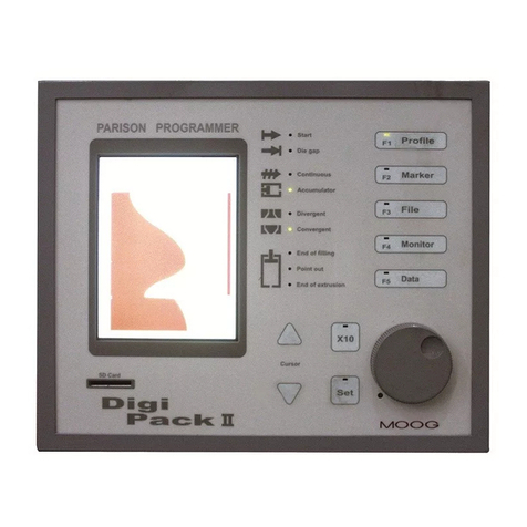
Moog IMI220-145D001 User manual

MOOG
Manual IMI220-145D001
Parison Controller

PARISON CONTROLLER moog
2MAN145-UM-D01A-EN Moog Italiana srl - Bergamo
Revision History
Document Revision
Hardware
Software Rev.
Author
Date
Preliminary
Preliminary
Preliminary
Lstrabla - nfrassine
6th Dec 2004
1.02
1.02
1.02
rfacchi - nfrassine
31st Aug 2005
MAN145-UM-A02A-EN
IMI220-145A002
2.01
rfacchi - nfrassine
5th Oct 2005
MAN145-UM-A03A-EN
IMI220-145A003
3.01
sverga - nfrassine
29th May 2006
MAN145-UM-A03B-EN
IMI220-145A003
3.01 - 3.02
sverga - nfrassine
June 2006
MAN145-UM-B01A-EN
IMI220-145B001
3.04 - 3.05
4.01 - 4.02 - 4.03 - 4.04
–4.05
sverga - nfrassine
June 2010
MAN145-UM-C01A-EN
IMI220-145C001
5.01
nfrassine
July 2012
MAN145-UM-D01A-EN
IMI220-145D001
6.07
sverga –mamoruso
July 2017
Revision: Number of the current revision application
inside in the PLC.
Revision Date: Date of the current revision application
inside in the PLC.
MASS Release: MASS version related to the actual
application.
Firmware: Firmware release; can differ from MASS
release

PARISON CONTROLLER moog
Moog Italiana srl - Bergamo MAN145-UM-D01A-EN 3
1 Installation.
1.1 Installation Overview.
Since there are many makes, models and vintages of blow moulding machines it is impossible to give specific
instructions as to the mounting, wiring and plumbing schemes to use. Different machines have different
requirements that the installer must ascertain before beginning the actual physical installation of the system. A
careful examination of the machine and some thoughtful planning beforehand will usually produce a good,
serviceable installation. There are some suggestions that hopefully will make your installation smooth and provide
many years of trouble free operation.
It is recommended that, if space is available on the machine, the programmer and its various electrical components
be mounted in a separate enclosure. While it might be possible to mount these components in the machine’s main
electrical cabinet, quite a bit of electrical “noise” and heat is usually generated there. While the Parison Controller
was designed with some degree of tolerance for these conditions it must be remembered that it is, in essence, a
computer.
To minimize any detrimental effects on the system that can be sometimes caused in such an environment, it may
be easier and wiser to circumvent any problems before they are created. The old adage “An ounce of prevention…”
can definitely apply here.
If using a separate enclosure or not, thoughtful layout of components is quite important. Remember, for future
troubleshooting it is important to consider accessibility to terminals to allow for voltage readings and the ability to
reach fasteners so components can be removed and replaced. Cable routing should also be considered to prevent
stretching of cables, straining of connections, pinch points and sharp edges that could damage a wire or cable.
Transducer and valve cables should be run through a “Seal-Tite” type of flexible, liquid tight conduit. Although it is
much faster and easier to run them over the machine unprotected, enclosing them in conduit provides protection
against physical damage as well as protection against insulation breakdown due to airborne chemical.
Cabling should also be run away from sources of heat (extruders, accumulators, and heater bands) and strong
electrical fields (motors, transformers, etc.).
The programmer can be mounted anywhere convenient to the operator station but should be located away from
areas where it could be damaged by falling objects or flooded by broken coolant or hydraulic lines.
Cable lengths to valves and transducers should be kept as short as possible to minimize line loss and signal
corruption, but long enough to provide movement of machine members for unrestricted operation and machine
maintenance. When routing cables it is wiser to avoid possible noise sources or areas of potential damage than to
minimize cable lengths.

PARISON CONTROLLER moog
4MAN145-UM-D01A-EN Moog Italiana srl - Bergamo
1.2 Hydraulic Installation.
Hydraulic installation involves the mounting and plumbing of filters, servo-valve manifolds, cylinders, etc.
If the programmer is being installed as a replacement for another programmer all the necessary components should
already be in place. If not, the following suggestions are offered:
Do not reuse old hose, pipe fittings or tubing. Contamination in old plumbing is almost impossible to
effectively remove and can cause problems in future servo-valve reliability. Old fittings that have been
painted and assembled with old thread sealing compounds will not only introduce contamination, but are
harder to work with and can contribute to added installation time.
Before assembling any new plumbing, inspect it carefully to insure that there are no metal filings or foreign
matter left over from cutting or assembly. Now is the best time to clean it out, before it can get into the
hydraulic system.
Replace the hydraulic oil or have it analyzed by a reputable lab. Depending on your maintenance program,
the oil may not have been checked for some time. Now is a good time to perform any oil-related
maintenance BEFORE the servo-valves are installed.
If you are replacing the oil remember to filter it as you pump it into the machine. New oil right from the
refinery is sometimes the dirtiest oil in the shop.
1.3 Hydraulic Filtration.
Clean oil is the key to reliable hydraulic system operation. Dirt, silt and sludge in the system increase operating
temperatures by decreasing heat exchanger efficiency and create excessive wear on pumps, directional and relief
valves and valve seats. Contamination breeds contamination by wearing hoses and other hydraulic components
from the inside.
Moog servo-valves are designed to operate with an ISO code of 14/11. While this may be lower than what you are
accustomed to, the benefits of improved filtration will show up not only in increased servo-valve life but will help to
reduce premature machine wear and the frequency of oil related failures.
Moog offer a full line of filters and filter systems with element ratings starting at 3 microns, flow-rates from 10 to
100 gallons per minute, and operating pressures as high as 3,000 psi. There are a number of good filter systems
available and, even if a Moog filter is not chosen, it is strongly urged you employ one of these other filter systems
on your machine.
High-pressure filter assemblies should be plumbed between the high-pressure hydraulic supply and the “P”
(pressure) port of the servo-valve manifold(s). Plumbing from the filter outlet to the “P” port should be completed
with steel tubing or pipe.
If the machine employs a hydraulic accumulator to maintain stability in the machine’s hydraulic system, the filter
should be installed after the accumulator and before the valve manifold(s).
1.4 Servovalve Manifolds.
Servo-valve mounting is accomplished with the use of manifolds for each head. These manifolds allow for easy
removal of the valves to facilitate system flushing or valve replacement in the event of failure.

PARISON CONTROLLER moog
Moog Italiana srl - Bergamo MAN145-UM-D01A-EN 5
Moog servo-valves used in blow moulding Parison control are most often internally piloted devices. This means
that the manifolds used will have 4 ports that connect to the machine’s hydraulic system:
“P” port is the incoming high-pressure supply to the valve.
“T” or “R” port is the servo-valve return to tank.
“A” or “C1” port is one of the controlled ports. This should plumb to one end of the programming cylinder.
“B” or “C2” port is the other controlled port. This should plumb to the other end of the programming cylinder.
Some manifolds may be supplied with an additional fifth port labeled “X”. These manifolds are designed for use
with hydraulic systems capable of supplying an independent source of pilot pressure. If the need for this port is
uncertain, contact Moog Field Engineering for additional information.
There is no specification as to which controlled port should plumb to which end of the programming cylinder. The
following suggestions are offered concerning plumbing:
Try to keep the overall length of the controlled port lines as close to equal as possible.
Keep the servo-valve manifold as close to the programming cylinders as possible. The shorter the length
of the control lines, the more accurate position control will be.
Try to plumb all the valves the same way. (All “A” ports to the top of the cylinders or all “B” ports to the top
of the cylinders.) This will reduce confusion and make wiring easier later.
It is EXTREMELY IMPORTANT that plumbing between the controlled ports of the manifolds and the programming
cylinders be completed with solid tube or pipe. Do Not Use Hoses To Make These Connections! Hydraulic supply
up to the filter and the return lines from the servo-valve manifolds can be done with hose if desired.
In a great number of cases, the solid hydraulic lines that connect the controlled ports to the programming cylinders
will provide enough support for the servo-valve and manifold combination. If the machine is prone to excessive
vibration it would be wise to fabricate some type of bracket to support the servo-valve assembly.
A typical servo-valve and manifold installation is depicted below:
Figure 1

PARISON CONTROLLER moog
6MAN145-UM-D01A-EN Moog Italiana srl - Bergamo
1.5 Servoactuators.
A servo-actuator is a device, which can be used to take the place of the standard hydraulic cylinder. It combines
the cylinder, DCDT position transducer and servo-valve manifold into one compact, pre-adjusted package. Servo-
actuators can help reduce hydraulic installation time significantly and make calibration faster and easier.
There are a number of servo-actuators available with different specifications and mounting hardware, therefore no
specific information will be supplied in this document. Please contact Moog if more information is required on a
specific model or type.
Figure 2
1.6 Flushing.
Once all the hydraulic work has been completed you can start the process of flushing the hydraulic system. This
step is recommended to remove as much of the foreign matter left behind in the hydraulic system as possible
before installing the servo-valves.
It is also recommended that the system be flushed every time the reservoir is drained and refilled, a cylinder is
replaced, or a pump or any other major hydraulic component on the machine is replaced.
The first step in flushing is to remove the servo-valves from their manifolds or actuators and replace with the proper
flushing blocks. Install the flushing element in the high-pressure filter assembly and make sure the dirt alarm has
been properly reset. (Flushing elements are identified by a red band printed around the filter element.)
Jog the pumps to insure that there are no major leaks in the hydraulic system. If all looks tight start the pumps and
allow them to run. After a short run time carefully inspect all the hydraulic fittings and lines to insure there are no
leaks.
Periodically check the filter dirt alarm on the high-pressure filter to see if it has tripped. If it has, stop the pumps and
replace the flushing element with a new one. Reset the dirt alarm and restart the pumps. Allow them to run while
periodically inspecting the dirt alarm.
The system has been satisfactorily flushed when the pumps can run for two complete hours without tripping the
dirt alarm.

PARISON CONTROLLER moog
Moog Italiana srl - Bergamo MAN145-UM-D01A-EN 7
After flushing is complete, stop the pumps and replace the flushing element with a standard high-pressure filter
element. Replace the flushing blocks with the servo-valves. Remember to reconnect the electrical connectors.
CAUTION
The flushing element is a LOW-PRESSURE element designed to be used in conjunction with the flushing
blocks. Failure to replace it with the correct high-pressure filter element after removing the flushing blocks
will result in the filter element collapsing and possibly damaging the machine.
NOTE
On some machines when the flushing blocks are installed in place of the servo-valves, hydraulically
operated devices may not function. The flushing blocks are configured to direct pressure back to tank
allowing the system to be flushed at low pressure. Because of this, no pressure will be created in the
hydraulic system.
1.7 A Word About Hydraulic Pumps.
One of the most common failures seen in parison control valves is a buildup varnish in the valve. This is usually
caused by oil overheating and breaking down. Most standard petroleum based hydraulic fluids begin to reach their
temperature specification somewhere between 130 and 150 degrees Fahrenheit (between 55 and 65 degrees
Celsius). While you may never surpass this temperature while running, it can easily be exceeded when the pumps
are off and the machine heats are on. The stationary oil in the valve absorbs the heat and can quickly surpass the
oil’s breakdown point.
To reduce the possibility of this happening it is suggested that anytime the heats are on, the pumps should continue
to run. The oil moving through the valve will actually act as a coolant and help to prolong servo-valve life.
1.8 Transducers Installation.
The Parison Controller uses DCDT position transducers to feed back programming cylinder position information to
the controller. A separate DCDT is required for each individual head.
If servo-actuators of the type described above are being used, the DCDT is integrated into the actuator package
and has been pre-adjusted at the factory. No further adjustment is required.
If the programmer is used in a position based application there is also a linear position transducer that is needed
to monitor the position of the reciprocating screw or accumulator push-out cylinder.

PARISON CONTROLLER moog
8MAN145-UM-D01A-EN Moog Italiana srl - Bergamo
1.9 DCDT Position Transducers.
In order to maintain accuracy and repeatability of the programming cylinder motion, care must be taken when
mounting the DCDT tooling position transducer(s).
A DCDT can be mounted with the transducer body as the stationary element and the core as the moving member
or the core can be stationary and the body can move. Whatever method is used, the stationary element must be
rigidly mounted on a non-moving portion of the machine frame to provide a reference for piston movement.
Please note the following precautions when mounting the transducer:
The core must move freely in the body. There should be no side loading of the core nor should the core
rod be bent in order to make it align with the transducer body.
Mountings for both core and transducer body must be rigid. There should be no free play in any of the
brackets and the brackets should be made of a stiff material, which will not bend or give, with normal
machine vibration.
Provision must be made to allow for adjustment of the stationary element of the transducer. The
transducer’s position will need to be adjusted during calibration to bring the programming cylinder’s stroke
into the usable portion of the DCDT’s stroke. The ability to align the body with the core will also make future
DCDT replacement easier, if necessary.
When designing the DCDT mounting brackets allow for some type of anti-rotational device to keep the core
and body properly aligned.
A typical DCDT transducer installation using the moving core method is depicted in the drawing below.
Figure 3
Note the provisions made for the vertical adjustment of the DCDT body and the anti-rotational arrangement
incorporated to keep the core and body aligned.

PARISON CONTROLLER moog
Moog Italiana srl - Bergamo MAN145-UM-D01A-EN 9
1.10 Linear Position Transducer (position based applications ONLY).
Since the profile is synchronized to the position of the push out ram, the Parison Controller requires a means to
track the ram throughout the push-out stroke. In addition, to keep the profile points properly positioned on the
Parison, the Parison Controller must have control over the accumulator or reciprocating screw’s FULL (End of Fill.)
and EMPTY (End of Extr.) points. Both of these tasks are accomplished by the signal provided from the linear
position transducer, also referred to as a linear pot.
The transducer can be mounted so that the shaft EXTENDS FROM the pot body during push-out, or RETRACTS
INTO the body during push-out, whichever makes for a more convenient mounting method.
As with DCDT’s, there are several precautions that should be observed when mounting linear position transducers:
The pot body and shaft must be as parallel to the push out ram as possible. This will prevent side loading
of the transducer shaft and premature failure of the bushings in the transducer body.
The transducer should never be at the full mechanical end of its stroke in either direction. When mounting
be sure that the shaft is at least 0.25” (~5 mm) from its mechanical end stop when the push out cylinder is
at full bottom (empty).
The body should be rigidly mounted to eliminate the possibility of movement caused by machine vibration.
There should be no more than 1/16 inch (~1.5 mm) of end play in the transducer shaft in the direction of
ram movement when the shaft is secured to the ram follower assembly.
The end of the shaft should never be screwed down tightly to the follower assembly. Instead, the ball joint
on the shaft should be allowed to “float” slightly up and down the securing screw. This will reduce any
stresses caused by the slight misalignment between transducer and cylinder that are always present.
Figure 4

PARISON CONTROLLER moog
10 MAN145-UM-D01A-EN Moog Italiana srl - Bergamo
Figure 5
2 System Architecture.
2.1 Terminal (Front).
The Panel Operator is the place where all the interactions happen between the operator and the Parison
Controller.
The Operative Panel is constituted by a LCD TFT 10.4 inches touch screen and by groups of buttons.
The Parison Controller looks as follows:
Leds panel
Rotary Knob
SET key
Usb Device
Buttons
Purge Command
Shift key

PARISON CONTROLLER moog
Moog Italiana srl - Bergamo MAN145-UM-D01A-EN 11
2.1.1 Fast Access Keys and Knob.
Figure 6
Entry Knob: Used to change the value of various functions.
Rotation in a clockwise sense to increment and anticlockwise
sense to decrement. It is also used as a SET key to confirm a
change.
Del: Delete key. When a field is focused and this button is
pressed the content of the field is erased.
Edit: This button allows to enter the Parison field and edit the
profile. The button LED is ON. Push the Edit button again to end
the Parison editing. The button LED turns OFF.
X10:Increase the sensitivity of the entry knob by a factor of 10.
When X10 is active the associated led is ON.
Purge: This button starts the movement of the heads to the purge position; as long as the key “PURGE” is active.
Shift: This button used contemporarily with another button changes the operation of it. This is explained for each
button in the relative pages.
2.1.2 Usb device.
Figure 7
Usb device: Allows to save or load the recipes on an external memory.

PARISON CONTROLLER moog
12 MAN145-UM-D01A-EN Moog Italiana srl - Bergamo
2.1.3 Display Led panel.
Figure 8
Start: Lit when the cycle Start (1 or 2) signal is received.
Die gap: Lit when the Die Gap signal is received (only in position accumulator
mode).
Continuous: Lit when the “Continuous Extrusion” machine type is selected.
Accumulator: Lit when “Accumulator” machine type is selected.
Divergent: Lit when “Divergent” die is selected. Normally it is reported to the
head number 1. If the work page visualizes another head this led reports to this
same head.
Convergent: Lit when “Convergent” die is selected. Normally it is reported to
the head number 1. If the work page visualizes another head this led reports to
this same head.
End of filling: Lit at the end of the accumulator filling (only in position accumulator mode).
Point out: Lit when each serial marker point is reached.
End of extrusion: Lit at the end of extrusion. (both in continuous extrusion and accumulator mode)

PARISON CONTROLLER moog
Moog Italiana srl - Bergamo MAN145-UM-D01A-EN 13
2.2 General page description.
2.2.1 Colours assignment for all pages:
Green numbers
The fields that can be reached by cursor and can be changed.
Grey numbers
The fields that can’t be reached by cursor and can’t be changed.
Blue bargraphs
Show the value of an analog output.
Yellow numbers
Show actual value.
Yellow bargraphs
Show actual value (feedback e.t.a.).
White
The texts on the screens.
2.2.2 Page Header:
Text left bottom: Shows
the actual recipe that is
working.
Center: Shows the page title.
Date and time of day: Show the actual day, date and hour of the system. For adjustment go to the Technical level
or a Resp. level password.
Text right bottom: (yellow) Shows the current level state:
Lock: No password inserted.
Acc. Resp: Access Responsible Level on. For changing this password enter in Technical
Level and enter in setup machine.
Acc. Tech: Access Technical Level on. This password is fixed by Moog.
The other one shows the current number page.
2.2.3 Page Bottom:
Bottom page: soft
key to change the
page
Alarm line: If there are one or more
alarms on the alarms page, the alarms
are displayed at the bottom of each
page.
This line shows the last alarm and changes the back colour depending on the priority. On the left of the text the
number shows the code of the alarm displayed at the moment.
Min and Max: Minimum and maximum are displayed in the status line.
In the example on the left the minimum valid value is 0, while the
maximum is 5000.

PARISON CONTROLLER moog
14 MAN145-UM-D01A-EN Moog Italiana srl - Bergamo
2.3 Change of Setpoints.
If the cursor is on a numeric, Boolean, multi text list, alphanumeric field (green), the value can be changed.
Numeric fields: insert the desired number with the rotation of the Entry Knob. In clockwise the numbers increase.
It is possible to insert the decimal value only rotating the Knob and it is possible to insert the value left of the dot
with X10 multiplication factor and entry knob. Confirm by Set key.
Boolean fields: switch to YES/NO with rotate Entry Knob. In clockwise it is YES selection. Confirm by Set key.
Multi text list fields: rotate Entry Knob (one or more times) to scroll forward or (one or more times) to scroll
backward until desired text is displayed. Press Set key to accept the change.
Alphanumeric fields: Insert the first character alphanumeric with the rotation of the Entry Knob, move to the right
using the shift key + entry knob, using again the entry knob insert the following character. When the string is
completed confirm by Set key.
If a field need not to be changed (i.e. after typing a wrong number or changing the intention) move the cursor
away.
When a field is in variation with the insertion of a new data the led near Set Key is lit and the field changes colour.
It is also possible to modify all the existing fields using the relative keyboard (double click on the field):
Figure 9
Figure 10
Figure 11
Figure 12

PARISON CONTROLLER moog
Moog Italiana srl - Bergamo MAN145-UM-D01A-EN 15
2.4 The Parison field.
2.4.1 Field appearance.
When parison field is displayed by browser, it's sub-divided into 4 parts:
Starting from left you can see:
Figure 13
Working point panel: vertical histogram showing current working point
(for selected head).
Serial markers panel: (visible if select ON in Setup Machine Page)
vertical panel containing a logic status diagram of serial marker status
along the profile. The left position is OFF, the right position is ON.
Synchronism panel: (visible if set 1 or plus at number synchronism on
Setup Machine Page) vertical panel containing from 0 to max 5 vertical
lines as programmed synchronization points; each synchronism signals is
defined through start and stop points (which define synchronism line
width) and through type.(with accumulator machine).
Profile panel: area where the profile appears (maximum 400 points).
Each point can get a value from 0 through 10000 (100.00%); the profile is
drawn making an interpolation among some basic points (masters),
highlighted by horizontal line. Interpolation can be of various types: Bezier
curves, linear, flat, parabolic 1 (parabola with tangent 0 on end point) or
parabolic 2 (parabola with tangent 0 on start point); an interpolation can
be selected in a different way for each area available between a master
and the next one. The parison field, besides showing current profile, can
display the offset between programmed profile and the feedback profile
actually present on the head. On a profile it is possible to place some
markers allowing to physically detect a parison point.
2.4.2 Editing profile.
The cursor can be moved on a parison field using UP, DOWN arrow keys. The cursor position is drawn by a dashed
line; when the field is focused, the cursor is drawn by a continuous line. In this phase any operation involving a
change in current profile invokes field editing (background colour becomes orange); the field shows both original
profile and that being edited (changing page is possible going back to original profile).
When focus is on parison field, these operations are allowed:
2.4.3 Normal functioning:
- Arrows
- by pressing UP/DOWN arrow keys it's possible to move the cursor by a point upwards or downwards.
- by pressing +/-keys it's possible to change the amplitude of the current cursor point; the value changes
according to the amount contained in Increase; the changed point is setup as a master.
- Entry knob
- bythe rotation it's possible to change the amplitude of the current cursor point; the value changes according
to the amount contained in Increment; the changed point is setup as a master.
- by pressing SHIFT + Rotation it's possible to move the cursor upwards or downwards.

PARISON CONTROLLER moog
16 MAN145-UM-D01A-EN Moog Italiana srl - Bergamo
2.4.4 Other possibilities.
It is possible to select (F5) how the vertical arrows have to work.
Move cursor: move the cursor up and down (default
functioning)
Next master: move the cursor among the masters
Drag master: drag the master up and down
Next marker: move the cursor among the markers
(visible if select ON in Setup Machine Page)
Drag marker: drag the marker up and down. (visible if
select ON in Setup Machine Page)
Drag SM: drag the Serial Marker up and down. (visible
if select ON in Setup Machine Page)
Selects profile: select a part of the profile. It is possible
to select an area of points (reverse mode): selection is
active from previous master to next master
Drag selection: drag the selection up and down. If an
area is selected, it is possible to move it: if the motion
meets a master, it will be cancelled
It is possible to select (F6) how the Knob has to work.
Rotate the knob to change the Value (default
functioning)
Rotate the knob to change the Base. To increase the
minimum value (base) of the whole profile: all points are
translated in such a way that the profile keeps the same
look. The base can be changed up to that the maximum
value of the profile is 100
Rotate the knob to change the Range. To increase/
decrease the whole profile range: all points are
proportionally changed in such a way that the profile
keeps the same look. The range can be changed up to
that the maximum value of the profile is 100
Rotate the knob to change the Smooth. The value can
be from 0.5 up to 2 and it is only for Bezier interpolation
Rotate the knob to setup the Serial Marker (if selected
ON in Setup Machine Page)

PARISON CONTROLLER moog
Moog Italiana srl - Bergamo MAN145-UM-D01A-EN 17
2.4.5 Other function keys possibilities.
by pressing the key DEL it's possible to remove a master on the profile, in correspondence to the cursor
point.
by pressing the function key programmed as Toggle marker (F2) it's possible to add or remove a marker
on the profile in correspondence with the cursor point. By the function key DEL it's possible to remove a
marker.
If a master and a marker are both on the same point, press the key DEL to remove the marker as first.
by pressing the function key programmed as Select interpolation (F4) it's possible to change the type of
the interpolation area between two masters, the choice selection is made among Bezier curves, linear, flat,
parabolic 1, parabolic 2.
by the function key programmed as Clear (F3) it's possible to completely delete the current profile. The
PLC profile will be updated only when the operation is confirmed by pressing the Set Key.
When the serial marker panel is visible (set the parameter to ON in Setup Machine Page), the following operations
are possible:
modify the serial marker using F5 to set Vertical arrows to Drag SM and F6 to select Knob as Setup SM.
The SM can be dragged using the arrows.
the status of the serial marker can be switched ON and OFF using the knob or +and -keys.
2.5 Functionality.
2.5.1 Safe Condition.
Necessary conditions to start issuing a new profile are:
Temperature Ok ON
Emergencies ON
Alarm OFF
machine in automatic ON
Purge OFF
Tooling OFF
The digital input “machine in automatic”has to be ON during the normal work and has to be OFF
during the machine configuration. (Machine type selection, number of heads selection, number of
point selection, number of extruder selection, output command type selection, heads and
accumulator calibration and die type selection)
2.5.2 Language packages.
PARISON CONTROLLER is supplied with a language package (application rev. IMI220145D001.X.XX). It is
possible to choose among the following languages:
English, Italian, German, French, Spanish, Portuguese, Danish, Russian, Turkish, Greek, Chinese and Japanese.

PARISON CONTROLLER moog
18 MAN145-UM-D01A-EN Moog Italiana srl - Bergamo
2.5.3 Elements.
PARISON CONTROLLER can be configured to manage up to 4 heads.
Each regulator uses an analog input to acquire the mandrel opening and an analog output to drive the mandrel
positioning actuator.
The regulator can operate in closed loop (with no-intelligent actuators) or in open loop (with intelligent actuators
that operate in closed loop stand alone).
The input value is calibrated in range 0% - 100.00% through definition of upper extreme voltage and lower extreme
voltage. In case of intelligent actuators the calibration points are set to 0 mV and 10000 mV if it is not necessary to
make the calibration.
PARISON CONTROLLER can be configured to manage 1 accumulator.
A regulator in position in accumulation mode requires that the accumulator management is setup on fourth channel.
The setpoint generated by thickness regulator depends on the accumulator position in injection stroke relating to
the total injection stroke.
Input value is calibrated in range 0% - 100.00% through definition of full accumulator voltage (100% and input
higher than empty position) and empty accumulator voltage (0% and input lower than full position). It is possible to
exchange the analog output polarity to ignore the actuator connection polarity. The default polarity value waits for
increasing voltage values to bring the accumulator to empty position.
The input calibration should be made in this way:
It is possible to indicate a voltage to be applied on extrusion control output and activate empty accumulator
calibration procedure. The system automatically detects mechanical end-of-stroke, stores this value and interrupts
extrusion control. Using manual methods, the accumulator should be brought to empty and full position and it is
possible to manually confirm the positions.
PARISON CONTROLLER can be configured to manage up to 2 extruders.
It is possible to decide whether to use the extruder or not and which channel it should be associated to. It can be
associated to:
A thickness regulator in continuous extrusion.
A thickness regulator in time accumulation.
Accumulator.
It is possible to decide whether the extruder is driven by an analog or digital command. In case of analog command
the output voltage of a channel is the speed setpoint. In case of a digital command two digital outputs allow increase
or decrease of speed.
Extruder with analog command:
oIt is possible to calibrate the input with: 0 speed voltage, maximum voltage, and maximum speed.
The speed is expressed in RPM.
oIt is possible to calibrate the output with: maximum speed, voltage to reach maximum speed.
oThese setpoints can be setup: speed to be reached, rising ramp in RMP/sec., falling ramp in
RPM/sec., minimum speed, maximum speed.
Extruder with digital command:
oYou can setup the maximum ON time for digital output depending on a manual command.
Timer Switch
The Parison Controller can manage a weekly timer switch to activate the machine heating system and it can
manage a production counter.

PARISON CONTROLLER moog
Moog Italiana srl - Bergamo MAN145-UM-D01A-EN 19
2.5.4 Access.
PARISON CONTROLLER manages 3 access levels to protect data entry:
1. minimum access for machine user. Lock: no password inserted.
2. responsible access for responsible. Acc. Resp. For changing this password enter in Technical Level and
enter in setup machine.
3. service access for installer/serviceman. Acc. Tech. This password is fixed by Moog.
Access to levels 2 and 3 is password-protected. Level 2 persists at power down and power up, while level 3 does
not.
2.5.5 Keyboard test page.
From the input/output page and in manual mode (digital input 13 has to be OFF)
Keeping pressed the button F7 (next to the button MENU 2) for 5 seconds it is possible to access the test page
Figure 14
In this page it is possible to:
Reset the password:
Figure 15
Print the pages:
Figure 16
chose the page number and press the softkey
Perform the touch calibration:
-
Figure 17
it is also possible to perform the touch calibration keeping pressed the SET
key (entry knob) for 10 seconds

PARISON CONTROLLER moog
20 MAN145-UM-D01A-EN Moog Italiana srl - Bergamo
2.5.6 Machine configuration.
Parison Controller can be configured to run in:
continuous extrusion with independent profiles
in continuous extrusion with unique profile
with accumulator position
time accumulator.
In the following figures it is possible to evaluate all the configurations supported by PARISON CONTROLLER (as
continuous extrusion or position accumulator).
2.5.7 Continuous Extrusion or Time Accumulator.
Figure 18
Table of contents
Other Moog Controllers manuals

Moog
Moog Silencer Series User manual

Moog
Moog Silencer series User manual

Moog
Moog MSD Servo Drive single axis system User manual

Moog
Moog MDS Servo Drive User manual

Moog
Moog DigiPack III J141-215 Mounting instructions

Moog
Moog D085-172 Quick start guide

Moog
Moog DS2110 User manual

Moog
Moog DigiPack 2 Mounting instructions