Moog Prizm 200750 Series User manual
10/100 Ethernet Converter
200750-xxxxx and 200910-xxxxx
OEM Board Version
Users’ Manual
nd
Installation Guide
(Rev. G)
February 10, 2011
Moog Components Group
Springfield Operations
750 West Sproul Road
Springfield, PA 190 4
E-Mail: mcg@moog.com URL: www.moog.com/components
Tel: 610-328-4000 Fax 610-605-6216
24/7 Technical Customer Su ort Hotline: 610-605-6101

Moog Com onents Grou 10/100 Ethernet Converter Manual February 10, 20011
Page 2 of 12
1
10/100 Ethernet Converter P/N – 200750-xxxx/200910-xxxx Overview ........................................................................ 3
1.1
Manual Revision History: ........................................................................................................................ 4
1.2
10/100 Ethernet Converter Revision History: .......................................................................................... 4
1.3
10/100 Ethernet Converter Dash (-) Number Definitions: ....................................................................... 5
1.4
O eration ................................................................................................................................................. 7
1.4.1
10/100 Ethernet Converter Indicators, Controls and Connectors: .................................................................... 7
1.4.2
10/100 Ethernet Converter S ecifications: ....................................................................................................... 9
1.4.3
10/100 Ethernet Converter Signals During O eration ................................................................................... 10
2
General 10/100 Ethernet Converter Installation Notes .................................................................................................. 11
2.1
Standalone 10/100 Ethernet Converter Installation Checkout Procedure .............................................. 11
2.2
10/100 Ethernet Converter with Motherboard Installation Checkout Procedure ................................... 12

Moog Com onents Grou 10/100 Ethernet Converter Manual February 10, 20011
Page 3 of 12
1 10/100 Ethernet Converter P/N – 200750-xxxx/200910-xxxx
Overview
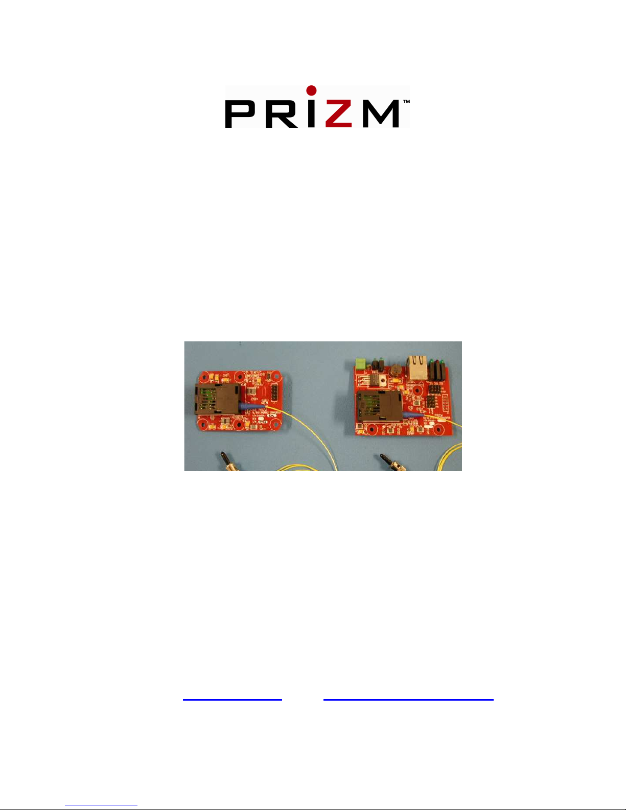
The PRIZM 10/100 Ethernet Converter rovides com letely trans arent media conversion between
10/100 Mb s, Full/Half Du lex Twisted Pair and fiber o tic Ethernet. Two units are required to form a
com lete data link. Twisted Pair Ethernet data is converted to fiber at one end of the link, and then
converted back to Twisted Pair at the other end to rovide a seamless Ethernet connection. The
converters allow negotiation between both ends of the link to the highest commonly su orted data rate.
A 1x9 fiber o tic transceiver module with a single-mode source laser (ty ically 1310 or 1550nm
wavelength) and either an integral or external wave division multi lexer (WDM) are used to allow for
single fiber o eration. It should be noted that the boards at either end of the link are functionally
identical, however the o tical transceiver on each board must have a different transmit wavelength than
the transceiver at the o osite end of the link when single fiber o eration is desired.
The Ethernet converters are su lied in two basic form factors. The first (200750-xxxx) is for s ace-
confined a lications and requires +5VDC. The dimensions of this version of the converters are 2” wide
x 3” long x .7” high. Six mounting holes are su lied for ease of installation. This unit rovides a 2x5
interface connector that can be either soldered to directly, or o ulated with a standard data header for
easy wiring. In addition to four ins for Ethernet twisted air data (TD+/-, RD+/-), the header contains
four ins for the monitoring of status signals (data traffic and negotiated data s eed at both the twisted
air and fiber interface). The final two ositions on the connector are reserved for su lied +5VDC (.5
Am max) and digital ground. The +5VDC in ut to the board is unfused, but the board is rotected by a
reversed diode, D1 in case ower is accidentally reversed to the board.
The second form factor (200910-xxxx) is slightly larger: 2.6” wide x 3.5” long x 0.9” high. Four
mounting holes are su lied on this board. This form factor is currently su lied in both +12VDC and
+24VDC versions. These units are su lied with an industry standard RJ-45 connector for the Ethernet
interface as well as individual LED indicators to dis lay the state of the four status signals described
reviously. A ty ical block diagram for these form factors is shown in Figure 1 below.

Moog Com onents Grou 10/100 Ethernet Converter Manual February 10, 20011
Page 4 of 12
1.1 Manual Revision History:
The manual has gone through the following revisions:
Original Demonstration Units
Rev A Describes Al ha Production Units
Rev B Included dash numbers for +12VDC owered units
Rev C Aligned Manual for new art numbering scheme
Rev D U dated roduct revisions and corrected various documentation errors
Rev F U dated contact information to reflect Moog Com onents Grou .
1.2 10/100 Ethernet Converter Revision History:
The 10/100 Ethernet Converter (200750-xxx) has gone through the following rinted circuit board (PCB)
and Assembly revisions:
PCB Revision A/Assembly Revision A Demonstration Boards
PCB Revision A/Assembly Revision B Al ha Production Units – Set u for Integral WDM and
+3.3V, extended tem erature range o tics
PCB Revision B/Assembly Revision C Revision B of the PCB and corres onding assembly
changes- Production Units
The 10/100 Ethernet Converter (200910-xxx) has gone through the following rinted circuit board (PCB)
and Assembly revisions:
PCB Revision A/Assembly Revision A Demonstration Boards/ Al ha Production Units – Set u
for Integral WDM and +3.3V, extended tem erature
range o tics
PCB Revision B/Assembly Revision A Revision B of the PCB and corres onding assembly
changes

Moog Com onents Grou 10/100 Ethernet Converter Manual February 10, 20011
Page 5 of 12
1.3 10/100 Ethernet Converter Dash (-) Number Definitions:
Over the course of their roduct life, both incarnations of the 10/100 Ethernet Converter have
undergone changes in the way art numbers are assigned. On older boards, a dash and three-digit
number followed the base number, while on newer revisions; a dash and four digits follow the base
art number. The dash numbers identify the s ecific board configurations:
Legacy 200750-XXX
-001 +5V standard o tics (1310nm laser) with integral WDM, demonstration unit
-002 +5V standard o tics (1550nm laser) with integral WDM, demonstration unit
-003 +3.3V extended tem erature o tics (1310nm laser) with integral WDM and 2x5 in header
-004 +3.3V extended tem erature o tics (1550nm laser) with integral WDM and no laced header
-005 +3.3V extended tem erature o tics (1550nm TX) with integral WDM and 2x5 in header and
no buffer on status ins
-006 +3.3V extended tem erature o tics (1310nm TX) with integral WDM and 2x5 in header and
no signal buffer on status ins
-007 Manually rounded corners. +3.3V extended tem o tics (1310nm TX) with integral WDM and
2x5 in header
-008 Manually rounded corners. +3.3V extended tem o tics (1550nm TX) with integral WDM and
2x5 in header
-009 +5V ext. tem (1310nm TX), integral WDM soldered to board. 2x5 data header not laced.
-010 +5V ext. tem . (1550nm TX), integral WDM soldered to board. 2x5 data header not laced.
200750-ABCD
A 1: 5VDC B: 1310nm C: SM, single fiber D: ST connector E; Misc
2: 12VDC 1550nm SM, dual fiber SC connector
3: 24VDC MM, dual fiber
.
Legacy 200910-XXX
-001 +12V su ly voltage, 1310nm SM TX with integral WDM. RJ45 laced.
-002 +12V su ly voltage, 1550nm SM TX with integral WDM. RJ45 laced.
-003 +9V su ly voltage, 1310nm TX with socketed SC, SM, RJ45 laced
-004 +9V su ly voltage, 1550nm TX with socketed SC, SM, RJ45 laced
200910-ABCDE
A 1: 5VDC B: 1310nm C: SM, single fiber D: ST connector E; Misc
2: 12VDC 1550nm SM, dual fiber SC connector
3: 24VDC MM, dual fiber

Moog Com onents Grou 10/100 Ethernet Converter Manual February 10, 20011
Page 6 of 12
10/100 Ethernet Converter Dash (-) Number Definitions (continued):
Legacy 300910-XXX
-001 +12V su ly voltage, 1310nm SM TX, ST connector. (obsolete)
-002 +12V su ly voltage, 1550nm SM TX, ST connector. (obsolete)
-003 +24V su ly voltage, 1310nm SM TX, ST connector.
-004 +24V su ly voltage, 1550nm SM TX, ST connector.
-005 +12V su ly voltage, 1310nm SM TX, ST connector.
-006 +12V su ly voltage, 1550nm SM TX, ST connector.
-007 +9V su ly voltage, 1310nm SM TX (high ower), ST connector.
300910-ABCDE
A 1: 5VDC B: 1310nm C: SM, single fiber D: ST connector E; Misc
2: 12VDC 1550nm SM, dual fiber SC connector
3: 24VDC MM, dual fiber

Moog Com onents Grou 10/100 Ethernet Converter Manual February 10, 20011
Page 7 of 12
1.4 peration
1.4.1 10/100 Ethernet Converter Indicators, Controls and Connectors:
INDICATORS:
200750 - +5V LED (green)- Indicates that +5VDC ower is available to the board.
+3.3V LED (green)- Indicates that the on-board 5V to 3.3V converter, U2, is o erational.
200910 - LED 1 (green)- Indicates rimary ower su lied to the board.
LED 2 (to /green)- Indicates that the onboard regulator is su lying +5VDC.
LED 2 (bottom/green)- Indicates that the onboard regulator is su lying +3.3VDC.
LED 3 (to /green)- Indicates that the device connected to the twisted air side of the unit
is o erating at a data rate of 100Mb s.
LED 3 (bottom/green)- Indicates that the device connected to the twisted air side of the
unit is o erating at a data rate of 10Mb s.
LED 4 (to /red)- Indicates that valid Ethernet data ackets are resent at the fiber o tic
interface.
LED 4 (bottom/red)- Indicates that valid Ethernet data ackets are resent at the twisted
air interface.
LED 5 (to /green)- Indicates that the fiber o tic link is carrying data at a rate of 100Mb s.
LED 5 (bottom/green)- Indicates that the fiber o tic link is carrying data at a rate of
10Mb s.
SWITCHES:
200750- There are no switches on the 200750 version of the Ethernet converter.
200910- There are no switches on the 200750 version of the Ethernet converter.

Moog Com onents Grou 10/100 Ethernet Converter Manual February 10, 20011
Page 8 of 12
JUMPERS:
200750- There are no user-configurable shunts on the 200750 version of the Ethernet
converters.
200910- JP1-4 are used to select how the four status signals will be dis layed. If all four
shunts are in osition 1-2, the onboard LED’s are used. If all four shunts are in osition 2-
3, the four status signals are sent to the 2x5 data header where they may be monitored as
the user wishes.
JP6-9 are used to select the Ethernet twisted air interface. If all four shunts are in
osition 1-2, the onboard RJ-45 connector is used. If all four shunts are in osition 2-3,
the twisted air signal is sent to the 2x5 data header.
CONNECTORS:
200750-
J1: 2x5 Connector
+5V VDC SUPPLY 10 o o 9 GROUND
TP_RCV 8 o o 7 FO_RCV
TP_SPEED 6 o o 5 FO_SPEED
TP_OUT- 4 o o 3 TP_OUT+
TP_IN- 2 o 1 TP_IN+
200910-
J1: RJ 45 Connector
RX + Pin 1
RX – Pin 2
TX + Pin 3
TX – Pin 6
J2: Power Connector
+VDC Su ly Pin 1
Ground Pin 2
J3: 2 x 5 Connector
GND 10 o o 9 GND
TP_RCV 8 o o 7 FO_RCV
TP_SPEED 6 o o 5 FO_SPEED
TX - 4 o o 3 TX +
RX - 2 o 1 RX +

Moog Com onents Grou 10/100 Ethernet Converter Manual February 10, 20011
Page 9 of 12
1.4.2 10/100 Ethernet Converter Specifications:
O tical Link Rate: ty ically 155Mb s bi-directional
Ethernet Data Rate: 10/100 Mb s full/half du lex
Fiber O tion: Singlemode or Multimode (with dual fiber or mode conditioner)
Laser Wavelengths: 1310 and 1550 nanometers
O tical Out ut Levels: -11dBm transmitter ower out ut at 1550 nm, ty ically
-11dBm transmitter ower out ut at 1310 nm, ty ically
Receiver Sensitivity: -33.5dBm receiver sensitivity, ty ically
Receiver Saturation: -3dBm, ty ically
O tical Budget: 22.5dB, ty ically
Misc.
O erating Tem erature: -20 degree C to +65 degree C
Storage Tem erature: -40 degree C to +65 degree C
Dimensions: (200750) 2.00 in x 3.00 in x 0.70 in
(50.80 mm x 76.20 mm x 17.78 mm)
(200910) 2.60 in x 3.50 in x 0.90 in
(66.00 mm x 88.90 mm x 22.80 mm)
Power Requirements: (200750) +5 Volts at .6 Am s (3.0 Watts), maximum
(200910) +12 Volts at 1 Am (12 Watts), maximum

Moog Com onents Grou 10/100 Ethernet Converter Manual February 10, 20011
Page 10 of 12
1.4.3 10/100 Ethernet Converter Signals During Operation
Note: In this section, it is assumed that the 10/100 Ethernet Converter is being used to maintain a
100Mbps data link between two devices capable o auto-negotiation. For other modes o operation,
please contact Moog Components Group.
The rovided status signals are generated using +3.3V logic. Although they are com letely TTL
com atible, it should be noted that the voltage range of the signals is ty ically 0V to +3.3V referenced
to user su lied Ground. In normal 100Mb s o eration the following indicator statuses should be
observed:
200750-
+5V Power LED – Lit green
+3.3V Power LED – Lit green
TP_SPEED – HIGH to indicate connection of a 100Mb s device locally via twisted
air wire. LOW in all other cases.
FO_SPEED – HIGH to indicate connection of a 100Mb s device at the o osite end
of the fiber link. LOW in all other cases.
TP_RCV – Pulled LOW and ulse stretched to 1.3ms er acket when receiving
data ackets at the twisted air interface. HIGH at all other times.
FO_RCV – Pulled LOW and ulse stretched to 1.3ms er acket when receiving
data ackets at the fiber interface. HIGH at all other times.
200910-
+5V Power LED – Lit green
+3.3V Power LED – Lit green
TP_SPEED – (To lit green) HIGH to indicate connection of a 100Mb s device
locally via twisted air wire. LOW in all other cases.
FO_SPEED – (To lit green) HIGH to indicate connection of a 100Mb s device at
the o osite end of the fiber link. LOW in all other cases.
TP_RCV – Pulled LOW and ulse stretched to 1.3ms er acket when receiving
data ackets at the twisted air interface. HIGH at all other times.
FO_RCV – Pulled LOW and ulse stretched to 1.3ms er acket when receiving
data ackets at the fiber interface. HIGH at all other times.
Data - Both flash red with transfer of data.
NOTE: During initial power up and data rate negotiation, the SPEED and RCV indicators will toggle
or a ew seconds be ore settling on a steady state.

Moog Com onents Grou 10/100 Ethernet Converter Manual February 10, 20011
Page 11 of 12
2 General 10/100 Ethernet Converter Installation Notes
NOTE: Please read all o this section prior to starting the installation process.
ALSO NOTE: It is important when installing the Converters that the units at opposing ends o the link
have transceivers with di erent optical transmit requencies. For this reason, it is assumed that the
converters will be used as a set with one unit being installed as per the standalone procedure below,
and the second unit being installed as part o a motherboard/daughtercard combination. I di erent
installation options are required, please contact Moog Components Group.
2.1
Standalone 10/100 Ethernet Converter Installation Checkout
Procedure
200750- For this 10/100 Ethernet Converter installation checkout rocedure, it is assumed that the
Converter will be mounted in a standalone configuration. +5VDC ower for the Converter is su lied
by the user’s DC ower su ly. See the next section for installing the Converter in a
motherboard/daughtercard configuration.
1. Mount the 10/100 Ethernet Converter directly to a chassis using the su lied mounting holes.
2. Su ly ower and ground using 16-gauge wire (or equivalent) (+5VDC .8 Am s) to ins 10 and 9
res ectively of the 2x5 header. Verify the correct voltage.
3. Connect two sets of twisted air wires between ins 1-4 and the desired Ethernet device. Kee in
mind that ins 1 & 2 are for data received by the Converter, while ins 3 & 4 are for data transmitted
from the converter.
4. Connect the four status signals from ins 5-8 of the data header to whatever external monitoring
device (LED’s, uProcessor) is to be used.
5. Connect o tical fiber between the air of converters.
6. Turn the ower on to both devices and verify that all ower LED’s are illuminated on both boards.
7. Using an Ethernet traffic generator, inger, or custom software, verify that data can be transferred
correctly between devices.
8. Verify o eration of status indicators as described in Section 1.4.3.

Moog Com onents Grou 10/100 Ethernet Converter Manual February 10, 20011
Page 12 of 12
200910- For this 10/100 Ethernet Converter installation checkout rocedure, it is assumed that the
Converter will be mounted in a standalone configuration. +12 VDC ower for the Converter is
su lied by the user’s DC ower su ly.
1. Mount the 10/100 Ethernet Converter directly to a chassis using the su lied mounting holes.
2. Su ly ower and ground using 16-gauge wire (or equivalent) (+12 or +24VDC) to a 2- in
Phoenix style connector. Pin 1 for VCC and in 2 for Ground. Verify the correct voltage.
3. Connect an Ethernet device to each converter using standard Ethernet cables.
4. Connect o tical fiber between the air of converters.
5. Turn the ower on to both devices and verify that all ower LED’s are illuminated on both
boards.
6. Using an Ethernet traffic generator, inger, or custom software, verify that data can be transferred
correctly between devices.
7. Verify o eration of status indicators as described in Section 1.4.3.
2.2 10/100 Ethernet Converter with Motherboard Installation Checkout
Procedure
For this 10/100 Ethernet Converter installation checkout rocedure, it is assumed that the Converter will
be mounted as a daughtercard to a customer rovided motherboard. +5VDC ower for the Converter is
su lied directly from the motherboard, and all data signals are interfaced directly to that motherboard.
See the revious section for installing the Converter in a standalone configuration.
Note: Only the 200750 revisions o the converters are currently capable o being mounted in a
daughtercard con iguration.
1. Verify the location of all motherboard/daughtercard connections on 2x5 header using in descri tions
in Section 1.4.1.
2. Mount the 10/100 Ethernet Converter to a user su lied motherboard with a 2x5 standard in data
header. Mounting holes may be utilized for additional security.
3. Connect o tical fiber between the air of converters.
4. Turn the ower on to both devices and verify that all ower LED’s are illuminated on both boards.
5. Using an Ethernet traffic generator, inger, or custom software, verify that data can be transferred
correctly between devices.
6. Verify o eration of status indicators as described in Section 1.4.3.
This manual suits for next models
1
Table of contents
Other Moog Media Converter manuals


