Moons' MDX+40 User manual

06 / 19 / 2023
Requirements
To begin, make sure you have the following equipment:
●A 24-60 VDC power supply
●A PC running Windows Vista/Windows 7 / Windows 8 / Windows 10 (32-bit or 64-bit) system
●A small flat-blade screwdriver for motor power cable connection
●One USB mini-B communication cable,Cable type: 2620-150
●One I/O cable
●For RS485, CANopen bus applications, a communication cable is required
●For the application of EtherCAT, a CAT5e network cable is required
Step 1 Installing the software
a) Download the Luna software.
b) Install the Luna on your PC.
c) Connector the drive to PC with USB mini-B cable.
a) Connect the drive to the DC power supply
Power Symbol Description Function Input specs
Main V+ Main Power + Supplying power to the motor power and control
sections 24~60VDC
V- Main Power -
AUX
AUX+ Auxiliary power + Auxiliary power is required for the following two
applications:
a) When the main power is cut off, the DSP part of
the drive needs to work normally
b) Use a motor with a brake, supplying power to
the brake.
24VDC±10%
AUX- Auxiliary power -
Note:
1) Please avoid connecting the power "+" and "-" in reverse, as it will damage the motor.
2) Please power on the motor after all the wirings on the motor are completed.
b) Ensure a proper earth ground connection to the drive's chassis.
MDX+
MDX+40/MDX+60/MDX+80 Quick Setup Guide
Step 2 Connecting the Power Supply
06 / 19 / 2023
Step 3 I/O and Communication Cable
●Connecting input/output signals (I/O)
IP20- Type (MDXR6、MDXR8)
STO2-
STO1-
X1-
X2-
X1_Opc+
X3
X5
XCOM
Y2
YCOM
Z-
B-
A-
GND
STO2+
STO1+
X1+
X2+
X2_Opc+
X4
X6
Y1
Y3
Z+
B+
A+
AIN
+5V
27 28
1 2
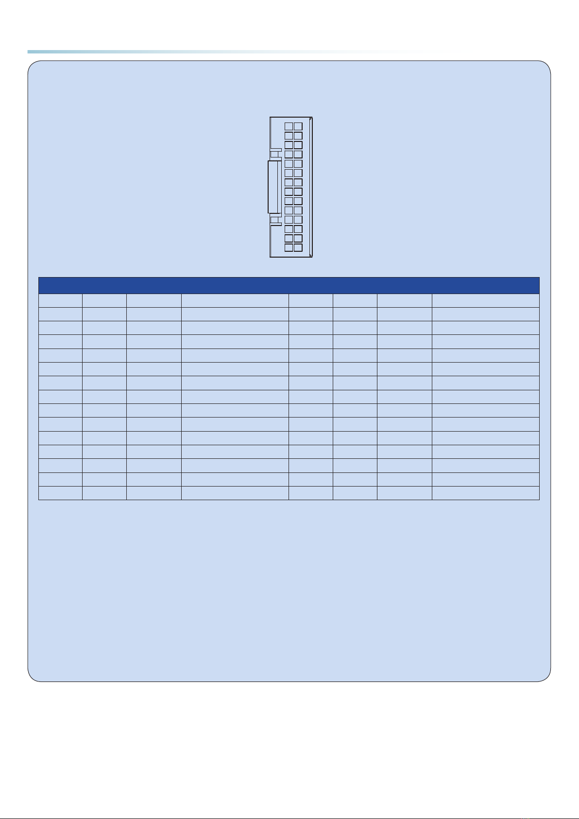
IP20 Type (MDXR6、MDXR8)
Pin Signal Color Function Pin Signal Color Function
1+5V Blue/White USER_5V Power + 2GND Blue/Black Digital Ground
3AIN Green/White Analog Input 4 AOUT- Green/Black Encoder Outout A-
5AOUT+ Blue Encoder Outout A+ 6 BOUT- Purple Encoder Outout B-
7 BOUT+ Yellow Encoder Outout B+ 8 ZOUT- Green Encoder Outout Z-
9 ZOUT+ Orange Encoder Outout Z+ 10 YCOM Red Digital Output COM Port
11 Y3 White Digital Output Y3 12 Y2 Black Digital Output Y2
13 Y1 Brown/White Digital OutputY1 14 XCOM Brown/Black Digital Input COM Port
15 X6 Gray/White Digital Input X6 16 X5 Gray/Black Digital Input X5
17 X4 Brown Digital Input X4 18 X3 Gray Digital Input X3
19 X2_Opc+ Pink/Red Pull-up for open collector X2 20 X1_Opc+ Yellow/Green Pull-up for open collector X1
21 X2+ Purple/White Digital Input X2+ 22 X2- Purple/Black Digital Input X2-
23 X1+ Yellow/White Digital InputX1+ 24 X1- Yellow/Black Digital Input X1-
25 STO1+ Orange/White STO1+ 26 STO1- Orange/Black STO1-
27 STO2+ Red/White STO2+ 28 STO2- Red/Black STO2-
Note:
1) X1+/X1-:Accept 5V single-ended or differential pulse signal, minimum pulse width 0.25μs, maximum pulse frequency 2MHz
2) X2+/X2-:Accept 5V single-ended or differential pulse signal, minimum pulse width 0.25μs, maximum pulse frequency 2MHz
3) X1_Opc+/X1-:Accept 24VDC signal, minimum pulse width 1μs, maximum pulse frequency 500KHz, (input signal valid limit: >16V, input
signal invalid limit: <8V, fuzzy area: 8V ≤ fuzzy area ≤ 16V)
4) X2_Opc+/X2-:Accept 24VDC signal, minimum pulse width 1μs, maximum pulse frequency 500KHz, (input signal valid limit: >16V, input
signal invalid limit: <8V, fuzzy area: 8V ≤ fuzzy area ≤ 16V)
5) X3/X4/X5/X6 - XCOM,accept NPN or PNP connection, that is, XCOM can be connected to 0V or 24V, (input signal valid limit: >16V, input
signal invalid limit: <8V, fuzzy area: 8V< fuzzy area <16V)
6) Y1/Y2/Y3 - YCOM,accept NPN or PNP connection, that is, YCOM can be connected to 0V or 24V
7) AIN:-10V ~10V,resolution 12bit
8) USER_5V power output maximum current is 100mA
9) The color of the connection wire marked in the above table refers to the 1116-XXX harness with shielding

06 / 19 / 2023
●Connecting input/output signals (I/O)
IP20- Type (MDXR4)
STO2-
STO1-
X1-
X2-
X1_Opc+
X3
X5
XCOM
Y2
YCOM
Z-
B-
A-
GND
STO2+
STO1+
X1+
X2+
X2_Opc+
X4
X6
Y1
Y3
Z+
B+
A+
AIN
+5V
27 28
1 2
IP20 Type (MDXR4)
Pin Signal Color Function Pin Signal Color Function
1+5V White USER_5V Power + 2GND Black Digital Ground
3AIN Pink/Red Analog Input 4 AOUT- Red/Black Encoder Outout A-
5AOUT+ Red/White Encoder Outout A+ 6 BOUT- Orange/Black Encoder Outout B-
7 BOUT+ Orange/White Encoder Outout B+ 8 ZOUT- Yellow/Black Encoder Outout Z-
9 ZOUT+ Yellow/White Encoder Outout Z+ 10 YCOM Gray Digital Output COM Port
11 Y3 Brown Digital Output Y3 12 Y2 Orange Digital Output Y2
13 Y1 Red Digital OutputY1 14 XCOM Yellow/Green Digital Input COM Port
15 X6 Yellow Digital Input X6 16 X5 Green Digital Input X5
17 X4 Blue Digital Input X4 18 X3 Purple Digital Input X3
19 X2_Opc+ Purple/White Pull-up for open collector
X2 20 X1_Opc+ Purple/Black Pull-up for open collector
X1
21 X2+ Gray/White Digital Input X2+ 22 X2- Gray/Black Digital Input X2-
23 X1+ Brown/White Digital InputX1+ 24 X1- Brown/Black Digital Input X1-
25 STO1+ Green/White STO1+ 26 STO1- Green/Black STO1-
27 STO2+ Blue/White STO2+ 28 STO2- Blue/Black STO2-
Note:
1) X1+/X1-:Accept 5V single-ended or differential pulse signal, minimum pulse width 0.25μs, maximum pulse frequency 2MHz
2) X2+/X2-:Accept 5V single-ended or differential pulse signal, minimum pulse width 0.25μs, maximum pulse frequency 2MHz
3) X1_Opc+/X1-:Accept 24VDC signal, minimum pulse width 1μs, maximum pulse frequency 500KHz, (input signal valid limit: >16V, input
signal invalid limit: <8V, fuzzy area: 8V ≤ fuzzy area ≤ 16V)
4) X2_Opc+/X2-:Accept 24VDC signal, minimum pulse width 1μs, maximum pulse frequency 500KHz, (input signal valid limit: >16V, input
signal invalid limit: <8V, fuzzy area: 8V ≤ fuzzy area ≤ 16V)
5) X3/X4/X5/X6 - XCOM,accept NPN or PNP connection, that is, XCOM can be connected to 0V or 24V, (input signal valid limit: >16V, input
signal invalid limit: <8V, fuzzy area: 8V< fuzzy area <16V)
6) Y1/Y2/Y3 - YCOM,accept NPN or PNP connection, that is, YCOM can be connected to 0V or 24V
7) AIN:-10V ~10V,resolution 12bit
8) USER_5V power output maximum current is 100mA
06 / 19 / 2023
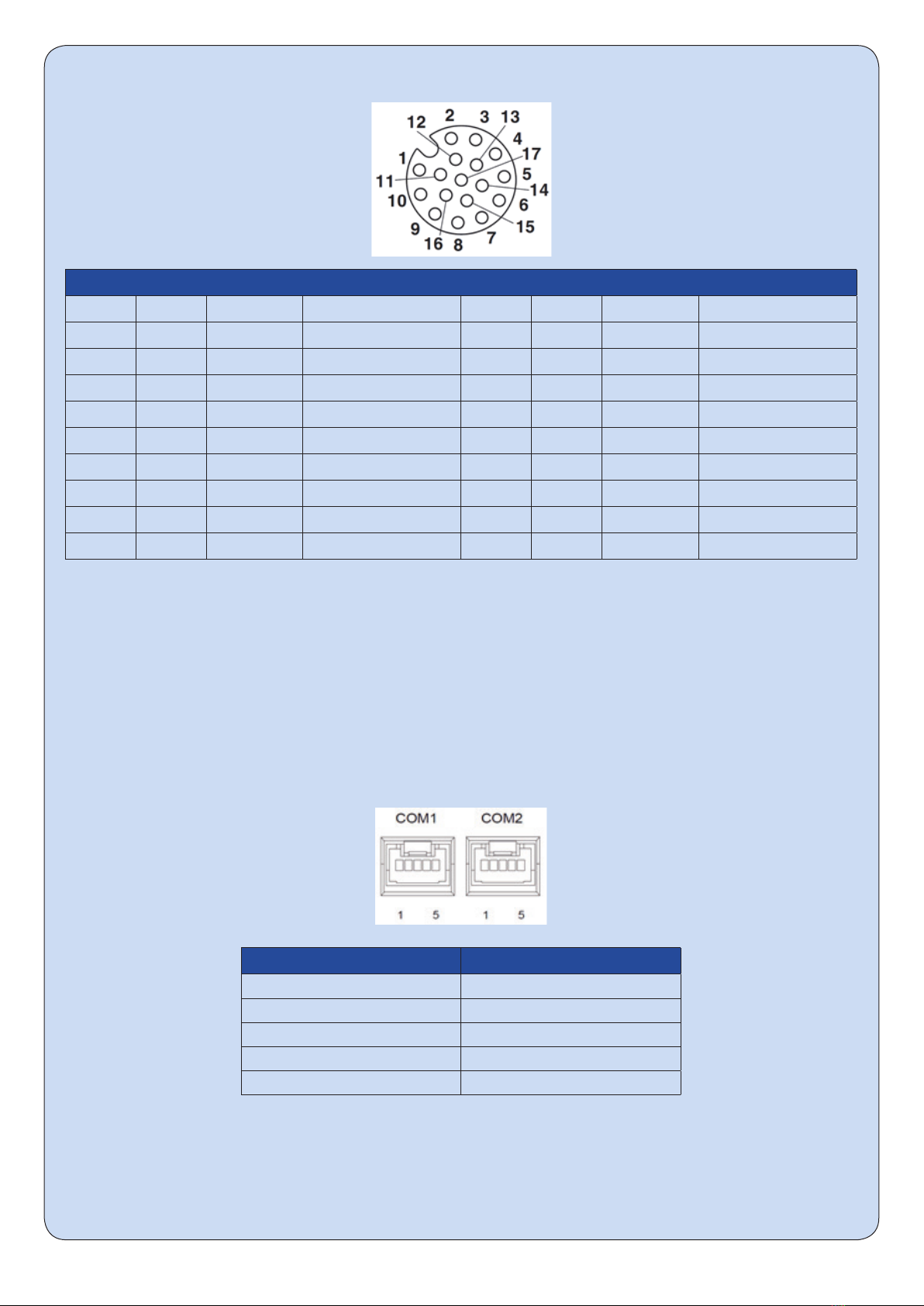
IP65-Type (MDXT4、MDXT6、MDXT8)
IP65 Type (MDXT4、MDXT6、MDXT8)
Pin Signal Color Function Pin Signal Color Function
1 X1+ Brown Digital Input X1+ 2 X1- Blue Digital Input X1-
3 X2+ White Digital Input X2+ 4 X2- Green Digital Input X2-
5X3 Pink/Red Digital Input X3 6 X4 Yellow Digital Input X4
7 XCOM Black Digital Input COM Port 8 5V Gray USER_5V Power +
9GND Red Digital Ground 10 AIN Purple Analog Input
11 Y1 Gray/Pink Digital Output Y1 12 Y2 Red/Bblue Digital Output Y2
13 YCOM White/Green Digital Output COM Port 14 STO1+ Brown/Green STO1+
15 STO1- White/Yellow STO1- 16 STO2+ Yellow/Brown STO2+
17 STO2- White/Gray STO2-
Note:
1) X1+/X1-:Accept 24V pulse signal, minimum pulse width 1μs, maximum pulse frequency 500KHz
2) X2+/X2-:Accept 24V pulse signal, minimum pulse width 1μs, maximum pulse frequency 500KHz
3) X3/X4 - XCOM,accept NPN or PNP connection, that is, XCOM can be connected to 0V or 24V, (input signal valid limit: >16V, input signal
invalid limit: <8V, fuzzy area: 8V< fuzzy area <16V)
4) Y1/Y2 - YCOM,accept NPN or PNP connection, that is, YCOM can be connected to 0V or 24V
5) AIN:-10V ~10V,resolution 12bit
6) USER_5V power output maximum current is 100mA
●Communication Cable
IP20-RC Type (MDXR4、MDXR6、MDXR8)
COM1/2 Pin Signal
1RS485+
2RS485-
3CAN_H
4CAN_L
5 GND
06 / 19 / 2023
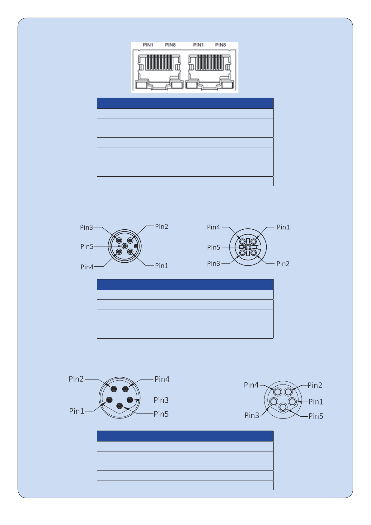
IP20-EC Type(MDXR4、MDXR6、MDXR8)
COM1/2(IN/OUT) Pin Signal
1 TX+
2 TX-
3 RX+
4NC
5 NC
6 RX-
7NC
8NC
IP65-Type (MDXT6、MDXT8)
COM1/2 Pin Signal
1RS485+
2RS485-
3GND
4CAN_H
5 CAN_L
IP65-RC Type (MDXT4)
COM1/2 Pin Signal
1RS485+
2RS485-
3GND
4CAN_H
5 CAN_L

06 / 19 / 2023
IP65-EC Type (MDXT6、MDXT8)
COM1/2(IN/OUT) Pin Signal
1 TX+
2 RX+
3 TX-
4 RX-
IP65-EC Type (MDXT4)
COM1/2(IN/OUT) Pin Signal
1 TX+
2 RX+
3 TX-
4 RX-
Step 4
●Run the Luna software.
●Apply power to the drive.
●The software will automatically identify the motor model and serial number.
●Use Luna software to configure control modes, I/O functions, etc., as well as simple motion simulation and
status monitoring.
●Use Luna software to set PID parameters, resonance suppression parameters, smoothing filter, etc.
06 / 19 / 2023
Appendix: Cable Description
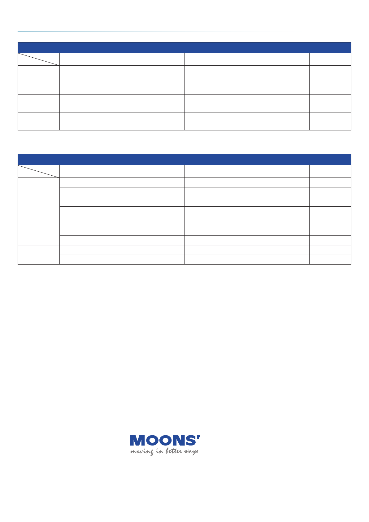
IP20 series model cable
Product
Cable Description MDXR4(RC) MDXR4(EC) MDXR6(RC) MDXR6(EC) MDXR8(RC) MDXR8(EC)
I/O Cable
Shielded 1664-XXX 1664-XXX 1116-XXX 1116-XXX 1116-XXX 1116-XXX
Unshielded —— —— 1101-XXX 1101-XXX 1101-XXX 1101-XXX
Power Cable Not Provided —— —— —— —— —— ——
EC
Communication
Cable
Not Provided —— —— —— —— —— ——
RC
Communication
Cable
Standard 3M 2111-XXX 2111-XXX 2111-XXX 2111-XXX 2111-XXX 2111-XXX
Note: XXX stands for cable length; 100 stands for 1m; 200 stands for 2m; 300 stands for 3m; 500 stands for 5m; 1000 stands for 10m
IP65 series model cable
Product
Cable Description MDXT4(RC) MDXT4(EC) MDXT6(RC) MDXT6(EC) MDXT8(RC) MDXT8(EC)
I/O Cable
Right Angle 1637-XXX 1637-XXX 1637-XXX 1637-XXX 1637-XXX 1637-XXX
Straight 1638-XXX 1638-XXX 1638-XXX 1638-XXX 1638-XXX 1638-XXX
Power Cable
Right Angle 1636-XXX 1636-XXX 1636-XXX 1636-XXX —— ——
Straight 1639-XXX 1639-XXX 1639-XXX 1639-XXX 1665-XXX 1665-XXX
EC
Communication
Cable
Right Angle —— 2664-XXX —— 2647-XXX —— 2647-XXX
Straight —— 2663-XXX —— 2648-XXX —— 2648-XXX
RJ45-Straight —— 2665-XXX —— 2646-XXX —— 2646-XXX
RC
Communication
Cable
Right Angle 2662-XXX —— 2632-XXX —— 2632-XXX ——
Straight 2661-XXX —— 2634-XXX —— 2634-XXX ——
Note: XXX stands for cable length; 100 stands for 1m; 200 stands for 2m; 300 stands for 3m; 500 stands for 5m; 1000 stands for 10m
MDX+Quick Setpu Guide
No. 168, Mingjia Road, MinbeiIndustrial Zone,
Minhang District, Shanghai
Tel: 021-5263 4688
Fax: 021-6296 8682
Web: www.moonsindustries.com
E-mail: [email protected]
This manual suits for next models
2
Other Moons' Power Supply manuals


