Alpha Technologies CFR 7.5K User manual

CFR
7.5K, 10K, 15K
Uninterruptible Power Supplies
FromAlpha Technologies
!!
!!
!Operator’s Manual

!!
!!
!Operator’s Manual
!!
!!
!CFR 7.5K, 10K, 15K
Uninterruptible Power Supplies

CFR 7.5K, 10K, 15K
NOTICE:
The CFR 7.5K, 10K and 15 K generates, uses and can radiate radio frequencies if not installed and
tested in accordance with the instructions contained in this manual. It has been tested and found to
comply with the limits established for a Class A computing device pursuant to part 15 of FCC rules
when it is operated alone. It also complies with the radio interference regulations of DOC which are
designed to provide reasonable protection against such interference when this type of equipment is
used in a commercial environment. If there is interference to radio or TV reception, which is deter-
mined by switching it on and off, relocate the equipment or use an electrical circuit other than the
one used by the CFR 7.5K, 10K and 15 K.
Toreducetheriskofelectrical shock and toensure the safe operationof the CFR 7.5K,10K,
15K,these symbolsare usedthroughout thismanual. Wherethey appearonly qualifiedper-
sonnelshouldcarryouttheinstructions.
A DANGEROUS VOLTAGE exists in this area. Use extreme caution.
ATTENTION: Important operating instructions. Follow them exactly.
CAUTION
Risk Of Electrical Shock
i
Save This Manual
It contains important installation and operating instructions.
Keep it in a safe place.

CFR 7.5K, 10K, 15K
Safety Checklists
DANGER: Sealedlead-acidbatteries with high energy and chemicalhazards are
used.Thismanualcontainsimportantoperationandsafetyinstructions.Onlyqualified
personnelshouldservice theCFR7.5K,10K,15K.
CFR 7.5K, 10K, 15K UPS Safety Checklist
Carefullyunpacktheunit.Reportanyshippingdamageatonce.
Readthismanual.Ifyouhaveanyquestionsaboutthesafeinstallation,operationormain-
tenanceoftheunit,contactAlphaTechnologies’customerservicedepartment.
Beforeinstallation,confirmthevoltageandcurrentinputrequirementsoftheload(s)is
compatiblewiththeunit’soutput.Alsoseethelinevoltageandcurrentiscompatiblewith
theunit’sinputrequirements.
Theunitshouldbeinstalledonadedicatedcircuit.
Wiringshould be done tomeet local electrical codes.
PlaceawarninglabelontheutilitypaneltotellemergencypersonnelanUninterruptible
PowerSupply(UPS)is inthebuilding.
Useproperliftingtechniqueswhenliftingormovingtheunit.
Theunithasmorethanonelivecircuit.ACpowermaybepresentattheoutputsevenifthe
unitisdisconnectedfromlinepower.
Battery Safety Checklist
AlwaysswitchtheunitbatterycircuitbreakerOFFbeforeconnectingordisconnectingan
externalbatteryback.Thisgreatlyreducesthechanceofaspark.
ii
DANGER: Do not expose the unit to rain or moisture.

CFR 7.5K, 10K, 15K
iii
Safety Checklists (Continued)
Therearedangerousvoltagesinsidetheunit.Onlyqualifiedpersonnelshouldperform
installationandmaintenance.
Livebatterywiresmustnottouchtheunit’schassisoranyothermetalobjects.This can
cause a fire or explosion.
Inspectthe batteriesonce ayear forsignsofcracks,leaks orswelling. Replaceas re-
quired.
Whenbatteriesareinstorage,chargethematleastonceeverythreemonthsfor
optimumperformanceandtoextendtheirlifetime.
Always replacebatteries with onesofidentical type andrating. Never install oldor un-
testedbatteries.
Useinsulatedtoolsduringservicing.
Removeallrings,watches,jewelryorotherconductiveitemsbeforeworkinginsidethe
enclosure.
Followlocalregulationsforthedisposalofbatteries.Recyclingisthebestmethod.
Never burn batteries to dispose of them. They may explode.
Never open the batteries. The contents are toxic.

CFR 7.5K, 10K, 15K
iv
Table of Contents
The emergency shutdown procedure is on the inside rear cover
1. Introduction .........................................1
1.1 TheCFRAdvantage.................................. 2
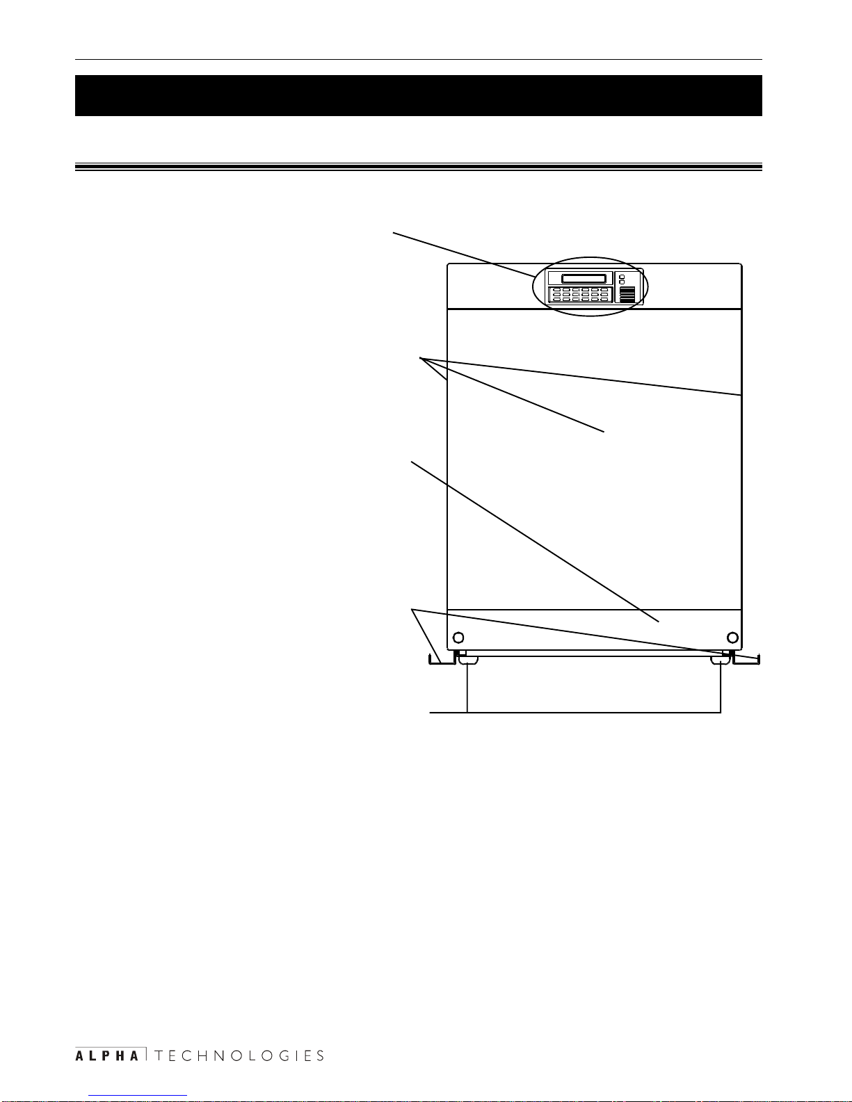
1.2 TheAlpha CFR 7.5K, 10K and 15K .......... 3
2. Installation .............................................8
2.1 Pre–Installation Checklist......................... 9
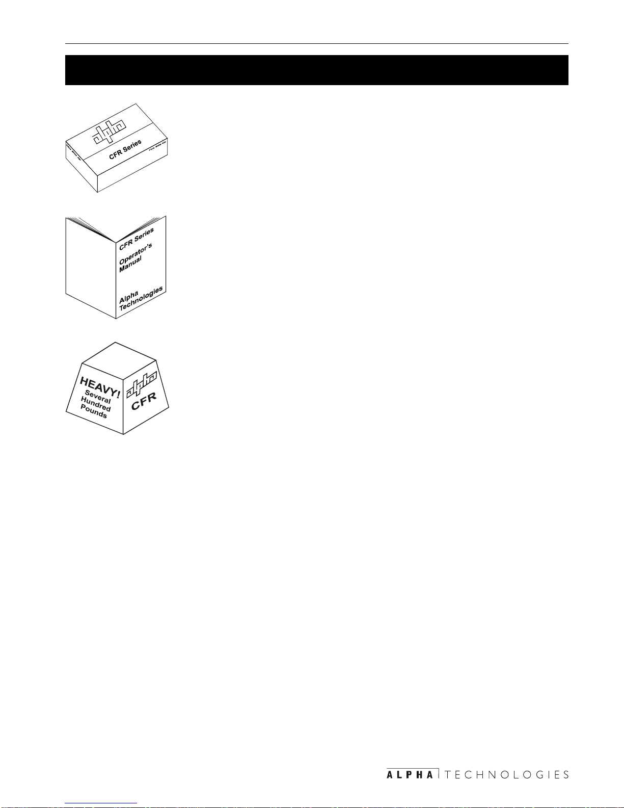
2.2 UnpackingandTransportation ................ 11
2.3 Connectingthe Internal Batteries............ 15
2.4 Mounting the Seismic Brackets ............. 18
2.5 Locking the Wheels ...............................19
2.6 Connecting the Terminal Blocks .............20
2.7 Connecting the External Battery Packs..21
2.8 Connecting the ExternalAlarm Port .......24
2.9 Connectingthe RS–232 Port .................. 25
2.10 TransformerOutput Load Sharing ......... 26
3. Operation ............................................29
3.1 Turning On the Unit ................................ 30
3.2 Turning Off theUnit ................................31
3.3 Testing the Unit ...................................... 32
3.4 TroubleshootingWith the SID.................33
3.5 Controlling the Unit With the Standard
InterfaceDevice(SID).............................34
4. Communication .............................37
4.1 SettingUp RS–232 Communications .....38
4.2 Usingthe OpeningMenu ........................ 40
4.3 MenuTree..............................................43
4.4 System, Input, Output & Battery Param-
eters ......................................................44
4.5 UserParameters .................................... 47
4.6 Maintenance Parameters ....................... 51
4.7 Installing and Using the External Modem 52
5. Maintenance ....................................60
5.1 Testing the Battery Backup Time............ 61
5.2 Troubleshooting...................................... 62
5.3 Returning the CFR toAlpha for Repairs .. 64
5.4 Replacingthe Internal Batteries..............64
5.5 ConfiguringtheInput/Output Voltage ......68
5.6 Battery Run Times .................................70
5.7 Specifications.........................................72
Index ............................................ 74
Warranty ...................................... 79

1
Section 1
Introduction
This section introduces you to the Alpha
7.5K, 10K and 15K CFR UPS’s:
• The CFR advantage (Section 1.1).
• An tour of the unit, it’s connectors, switches and
control panels (Section 1.2).

1 Introduction 2
1.1 The CFR Advantage
!Advanced Power Protection Technology
Alpha’sCFR UninterruptiblePower Supply(UPS)provides continuousand conditioned
computer-gradeACpowerfor computersystems, point ofsale terminals, processcontrols,
telecommunications,cable TVheadend,broadbandLAN,manufacturingcontrolsystems,
hospitalcritical care andlab equipment.
!Regulation
Theunitmaintains±1%output regulationwithout usingthebatteries.Evenwith inputvoltage
fluctuationsas great as+10% or –20%,the output isconstant regardless ofthe load’s size.
!Isolation
Theoutput istotallyisolated fromthe input toprotect theloadsfrom spikes,surges and line
noise.The ferroresonant transformer providesnon-degradable spikeand surge protection.
!ExtendedBackupCapability
Alpha'sEBP Series externalbattery packs extendsbackuptime duringpoweroutages.
Installingthe battery packis as simpleas plugging itin.
!Self Test Function
Thebuilt-in selftestchecks allcritical areas,includingthe batteries,to ensureoptimumper-
formance.
!Load and Overload Information
Thedisplay panelsshows theloading andtells youwhen theunit isoverloaded.
!Generator Ready
Theunithas frequencysenseand constantslewfrequencysynchronizationcircuitsfor
trouble-freeoperation withmoststandbygenerators.
!AdvancedCommunicationsCapabilities
TheRS–232 communications port isSNMP and modemcompatible.
!Safety
Alphahasdesignedthe CFR to meet or exceed the UL, CSA orVDEsafetystandards. This
commitmentto safetymakesAlphaTechnologiesa leaderin thepowerindustry.

31 Introduction
1.2 The Alpha CFR 7.5K, 10K and 15K
Complete the following for your records
Serial # __________________________________
Options __________________________________
PurchaseDate ____________________________
This CFR was purchased from
Dealer ___________________________________
City _____________________________________
State/Province_____________________________
Zip/Postal Code ___________________________
Country __________________________________
Telephone#_______________________________
Fax # ____________________________________
E Mail ___________________________________
Save The Original Shipping Container
Ifyouneedtoreturntheunitforservicing,packitintheoriginalshipping
container.Alpha isnot responsible fordamage causedby the improper
packagingofreturnedunits.
Read This Manual
Beforeinstallation,becomefamiliarwithyourunitbyreviewingtheproce-
duresanddrawingsinthismanual.Ifyouhaveanyquestionsaboutsafe
installation,operationormaintenance,contactAlpha’scustomerservice
department.
Transportation And Site Planning
Theweightof theunit andoptionalbattery packscanbeasmuch as1,500
lbs(680 kg).A safemeans oftransportationtothesite, liftingthe cabinet
intoposition andproperfloor supportmust bedevised.

1 Introduction 4
1.2 The Alpha CFR 7.5K, 10K and 15K (Continued)
1.2.1 Front Panel
Display Panel
Thisis eitherthe StandardInterfaceDisplay
(SID)(Section 3.5)or theoptional Intelligent
InterfaceDevice (IID)(Alphamanual#018–029–
B0–001).
Front and Side Panels
Thesepanels are removableto allow accessto
theunit’s interiorinorder tochange the batter-
ies,perform maintenance,etc. (Section 2.3).
Front Panel Grill
Thispanel is removableto allow accesstothe
screwsthatattachthefront paneltotheunit,the
frontwheel brakes orto the slotsto allow afork
liftunder theunittotransportittotheinstallation
site(Sections 2.2, 2.3).
Seismic Brackets
Thesesecure theunit tothefloor ifrequired by
thelocal codes.They are removable(Section
2.4).
Casters
Theselet youmove theunit. Ifthe seismicbrack-
etsare removed,theyshould belocked oncethe
unitis moved into itsfinal position (Section2.5).

51 Introduction
1.2 The Alpha CFR 7.5K, 10K and 15K (Continued)
1.2.2 Rear Panel
Fans
Thesefour fanscooltheunit.They mustnot beblocked.
Output Terminal Block
Thisis theunit’soutput power connector. SeeSection
2.6for wiringinformation.
Thecover plate strainreliefaccepts either ¾or 1 inch
conduit.
Output Circuit Breaker
Thisprovidesprotection to the load and can be used as
anoutputpower on/offswitch.
Output Receptacles
Theseare plug-inconnectorsfortheunit’soutput power.
Theyare factoryconfigured toyour specifications.
Figure 1.1
RearPanel

1 Introduction 6
1.2 The Alpha CFR 7.5K, 10K and 15K (Continued)
Battery Circuit Breaker
Thisprotects theunit’sinverter andDC circuits and
canbe used asa battery poweron/off switch.
TIP: Itshouldbe turnedoff whenevertheunit
isturned off formore than afew hours oris
beingserviced. The battery canbe drained if
thisbreaker isaccidentally left on.
External Ground Lug
Thisprovides asingle point groundconnection.Al-
waysfollow yourlocal electricalcodefor correct
grounding.
Battery Pack Ground
Thisconnector groundstheexternal EBP144series of
batterypacks tothe unit.
External Battery Connector
Itaccepts astandardplug fromeitherAlpha's EBP
seriesbattery pack or acustom battery source(Sec-
tion2.7).
Input Circuit Breaker
Thisprovides protectionforthe unit.It can beused as
aninputpower on/offswitch.
Input Terminal Block
Thisis theunit’soutput power connector. SeeSection
2.6for connectioninformation.
Thecover plate strainreliefaccepts either ¾or 1 inch
conduit.

71 Introduction
1.2 The Alpha CFR 7.5K, 10K and 15K (Continued)
ExternalAlarm Connector
ThisRJ–45 connectorallows theconnection ofan
externalalarmpanel oranemergencyshutdown
switch(Section 2.8).
RS-232 Connector
ThisDB–9port provides RS–232 communication
(Section2.9).
External IID
AnexternalIIDplugsinto thisconnector forremote
controlandmonitoring.

8
Section 2
Installation
This section shows you how to unpack,
install and connect the Alpha 7.5K, 10K
and 15K CFR UPS’s:
• A pre-installation checklist (Section 2.1).
• How to unpack and transport the unit
(Section 2.2).
• How to connect the internal batteries
(Section 2.3).
• How to secure the unit with the seismic brackets
or the wheel locks (Sections 2.4 and 2.5).
• How to wire the unit’s input and output terminal
blocks (Section 2.6).
• How to connect and disconnect the external bat-
tery packs (Section 2.7).
• How to connect the external alarm port (Section
2.8).
• How to connect the unit to RS–232 communica-
tions (Section 2.9)
• How to prevent the output transformer from be-
ing overloaded (Section 2.10)

92 Installation
2.1 Pre–Installation Checklist
2.1.1 Site Preparation
Installtheunituprightinadry,well-ventilated,dustfreeenvironment.Theremustbeatleast
6inches(152mm)betweentheunitandthewall(s)forcoolingandaccesstothefrontand
rearpanels.Donotplacetheunitnexttoairconditioningorheatingthermostats.
Donotconnecttheunittolineconditioningequipment.Thiscancauseimproperoperation
ofboththeunitandtheequipment.
Donotconnectequipmentthatproduceselectricalnoisesuchasmotors,relaycontrol
circuits,copiersorlaserprinterstotheunit’soutput.
Placeawarninglabelontheelectrical panelso emergencypersonnel knowaUPSisinthe
building.Labeltheservicepanel(s)toidentifythecircuit(s)supplyingandbeingsuppliedby
theunit.
Theunit andoptionalbattery cabinethas acombinedweight ofup to1,500lbs (682kg).
Verifythat thefloor at theinstallation sitecan support atleast 375lbs /caster(170 kg/
caster)withoutunduestress.
2.1.2 Grounding & Utility Line
Installahardwiredground.Sincemanyolderfacilitieshaveimpropergrounding,aqualified
electricianshouldinspectboththewiringandthegroundingbeforeinstallation.
Measurethelinevoltageatthemainelectricalpanel.Comparethatreadingwiththeinput
rangeaslistedinthetablebelow.Thelinevoltagemustbeinwithintherangeofinput
voltagesforthatunit.
Forinformationaboutreconfiguringtheunit’sinputoroutputvoltage,seeSection5.5,
“ConfiguringtheInput/OutputVoltage.”ForfurtherinformationcontactAlphaTechnologies
customerservicedepartmentaboutvoltagereconfiguration.
tupnItinUtupnItinU tupnItinU tupnItinUtupnItinU )CAV( egatloVtupnIegatloVtupnI egatloVtupnI egatloVtupnIegatloVtupnI )CAV(egnaR
042042 042 042042252ot612252ot612 252ot612 252ot612252ot612
032032 032 032032242ot702242ot702 242ot702 242ot702242ot702
802802 802 802802612ot881612ot881 612ot881 612ot881612ot881

2 Installation 10
Theunit should bewired to dedicatedcircuit equipped witha properly sizedcircuit breaker.
Thebreaker’ssizeistheunit’smaximuminputcurrent(asgiveninthespecifications)plus
25%.
Forexampleif the unit draws 32.0 Ampsof current at 208 VAC, adding25%the input
currentbecomes 40.0 Amps. A 40Ampcircuit breaker would beOK. Always follow the
localelectricalcodewheninstallingorsizingcircuitbreakers.
Wiringshouldonlybedonebyqualifiedpersonnelandcomplywiththelocalelectricalcode.
2.1.3 Standby Generator (If Used)
Theunithasfrequencysensecircuitsforoperationwithmoststandbygenerators.Usea
generatorequippedwithelectronicspeedandvoltagecontrols.
Beforeinstallationseethatthegenerator’soutputvoltagemeetstheunit’sinputvoltage
requirementsas shown onboth nameplates.A240 VACunitmust beattachedto a240
VACgenerator.
2.1.4 Installation Sequence
Alpharecommends youinstall andwire theunit inthis sequence:
1 Unpackandtransport theunit tothe installationsite(Section 2.2,“UnpackingandTrans-
portation”).
2 Connectthe internal batteries(for the 7.5Kand 10K seeSection 2.3, “Connectingthe
InternalBatteries”, forthe 15Ksee Section2.7,“Connecting theExternal BatteryPacks”).
3 Removeor bolt downtheseismic brackets (Section2.4, “Mounting theSeismicBrack-
ets”).If thebrackets arenotused, lockthe wheels(Section2.5, “Lockingthe Wheels”).
4 Connectthe inputand outputterminal blocks(Section 2.6,“Connecting theTerminal
Blocks”).
5 Ifused,connecttheexternal batterypacks (Section2.7, “ConnectingtheExternalBattery
Packs”).
6 Ifused,connecttheexternalalarmport (Section2.8, “Connectingthe ExternalAlarm
Port”).
7 Ifused, connectthe RS-232link(Section 2.9,“Connecting theRS–232 Port”).
8 Makesure theoutputtransformerisnotoverloaded(Section2.10,“TransformerOutput
LoadSharing”).
2.1 Pre–Installation Checklist (Continued)

11 2 Installation
2.2 Unpacking and Transportation
TIP: Ifitems are missing or damaged,contactAlpha and the shippingcompanyat
once.Most shippers haveashort claim period.
WARNINGS:
1)Before unpackingtheunit, makesurethat theshipping pallet ison alevelworking
surfaceand thatyou canaccessthe frontof thepallet witha forklift.To preventdamage,
movethe unpacked unitas close aspossible to theinstallationsite.
2)To avoidbattery damage and apossibleshock hazard do nottipor tilt the unitorthe
batterycabinet.
Tools and Materials Required:
•Forkliftorothermeans oftransporting heavyobjects (upto1500lbs,680 kg).
•Sharpknife orrazor blade.
•ScrewdriverorpowerscrewdriverwithPhillipsbit.
•15/16 inch socket wrench.
• Vice grips or a second15/16 inch socket wrench.
Procedure:
1
Usea sharp knifeorrazor blade tocut the
tapedseams on the topof the box.Re-
movethe cardboard fromthe unit’stop
surface.

2 Installation 12
2.2 Unpacking and Transportation (Continued)
4
Removethe plasticwrap fromaroundtheunit.
2
Removethe cornersupportpieces bylifting
themupand away.
3
Removethe screwsholdingtheseplywood
stripstothe palletwith a Phillipsscrewdriver.
Liftthe boxoff thepallet.

13 2 Installation
2.2 Unpacking and Transportation (Continued)
WARNING: Do not use a pallet jack or similar
devicefor movingthe unitsinceonly oneblade
ofthejackwillfit underthe unit.Ifother trans-
portingdevices areemployed,use extreme
cautionand getothers tohelp youinsupport-
ingthe equipment.
7
Adjustthe forks toan outside widthof 15 inches.
Placethemunder theunitthroughtheopening
createdby removingthepanel in
6
.Ensure the
forksare fullyinserted beforelifting theunit offthe
pallet.
6
Pullthe frontlower panelforward toremove it.
5
Attachvice grips tothebolt shaft orattach a
15/16 inch socket wrench to the bolt head
fromunder thepallettopreventthe boltfrom
movingwhileyouunscrewthe nuts.
Using a 15/16 inch socket wrench, remove
thefournuts securingthe unittothe pallet

2 Installation 14
2.2 Unpacking and Transportation (Continued)
8
Liftthe unitoff ofthepallet. Removethe wood/
foamshock absorber.Transportitto theinstalla-
tionsite.
WARNING: Do notletthe forksextendout
pastthe backofthe unit.
Unpacking and Transport Finished
This manual suits for next models
2
Table of contents
Other Alpha Technologies Power Supply manuals

Alpha Technologies
Alpha Technologies APP60S User manual

Alpha Technologies
Alpha Technologies ALPHA OUTBACK ENERGY LPS36 User manual

Alpha Technologies
Alpha Technologies CXPS-E101 User manual

Alpha Technologies
Alpha Technologies MPS48-7M User manual

Alpha Technologies
Alpha Technologies GMX-915 User manual

Alpha Technologies
Alpha Technologies Alpha Outback Energy AlphaCap-665 User manual

Alpha Technologies
Alpha Technologies CXPS-W Series User manual

Alpha Technologies
Alpha Technologies APX Series User manual

Alpha Technologies
Alpha Technologies CXPS-FR3 Quick start guide

Alpha Technologies
Alpha Technologies CXPS-E3 19 Quick start guide