Morgan MEDesign BASIC-ONE CSA-UL Manual

December 2015 Version 2.2
98/37/EC
89/336/EEC
73/23/EEC
93/42/EEC
Manual Covers Models:
BASIC-ONECSA - UL
BASIC-ONE
Maintenance ~ Service Manual
!
!
Morgan MEDesign
, Inc. - Maintenance ~ Service Manual BASIC-ONE -
2005 Page 1
MAINTENANCE GUIDELINES
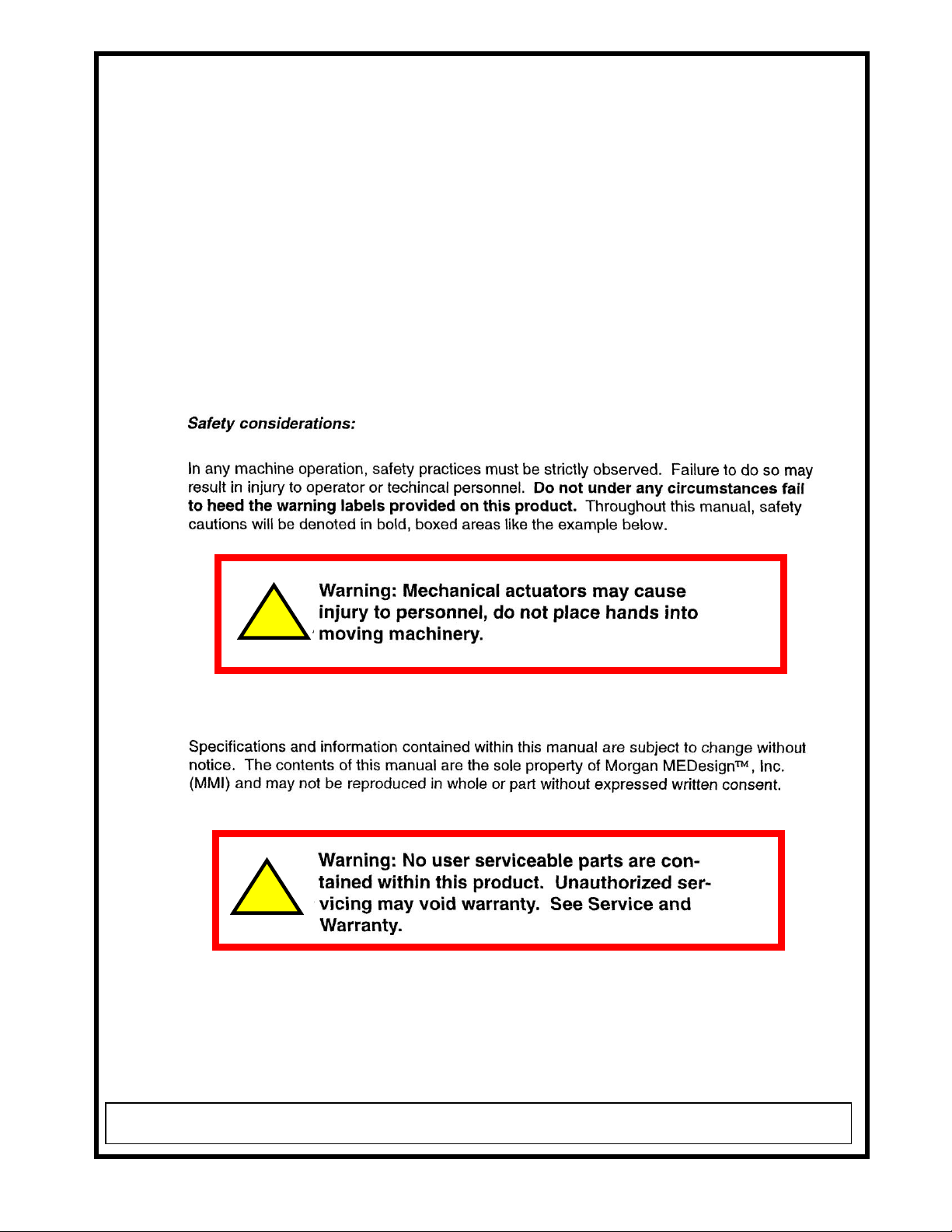
It is the responsibility of the user to perform periodic maintenance
procedures to insure that your table remains in optimum service for many
years. The factory recommendation is towards a twelve week cycle of
attention. The procedure should only take a small amount of time and is
quite straight-forward. During the maintenance procedure take care to detach
the table from the mains power supply whilst cleaning and re-attach the table
for the portions of the procedure that involve table movements.
Do not access any the internal cavities of any control box or electrical
assembly. Do not reach under the table top during any motion instigated by
the controller(s). Do not sit or lay on the table during the procedures.

MAINTENANCE PROCEDURES
1. Unplug or disconnect the table from the AC mains.
2. Starting from the base of the unit examine all harnesses and wires for
evidence of cracking, insulation displacement, fraying or other loss.
Determine the seriousness of any such damage and consider
replacement parts.
3. Check the integrity of fasteners that keep wires and cables in place.
4. Check that bolts, nuts, thumbscrews, screws and other hardware
items are secure.
5. Undo the locking mechanisms on the wheels and move the table
upon the floor in all four directions to insure mobility of the wheel
casters. Relock in position.
6. Note any lubricant leakages or stains that may have arisen onto or
from bearing surfaces.
7. Using a cloth and an industrial cleaner containing alcohol wipe down
surfaces which may have received patient exposure and/or contact.
Wipe down all horizontal surfaces twice.
8. Insure that all labels are firmly in place and are not starting to be
frayed or faded. If found, replace such labels with ones ordered from
the manufacturer.
9. Using a commercial vinyl cleaner and/or preservative clean and
cosmetic the vinyl top. Use the cleaner on all exposed sides insuring
that all elements of grease and grime are removed. Take care to
include seams and cracks, sides and every surface that can be
reached by a cloth held in the hand.
10. Wipe down the power cord using a damp cloth or sponge. Let dry.
11. Reconnect the table to AC mains.
12. Using the provided control unit(s) translate the table through all
its movements, taking each movement in sequence. Do not activate
simultaneous movements. Retain the UP-DOWN movement, if
provided, as the last procedure.
13. Listen for unusual noises during the operation of the table. Note any
clicks, snaps or loud scratching, scraping, growling or other noises.
14. Wait 5 minutes for the safety circuits that monitor duty cycle to
re-sync. This is an internal feature and is related to power cycles
in each motor assembly.
15. Check under the table base for captive debris and in general
examine the control and movement rods for evidence of
lubrication leaks.
16. If provided, fill out the Maintenance Schedule.
Morgan MEDesign
, Inc. - Maintenance ~ Service Manual BASIC-ONE -
2005 Page 2
MAINTENANCE SCHEDULE
EL HORARIO DE MANTANIMIENTO
RECEIVED
RECIBIDO
+ 1 YEAR
+ 2 YEARS
+ 3 YEARS
+ 4 YEARS
+ 5 YEARS
___-200__
___-200__
___-20___
___-20___
___-20___
___-20___
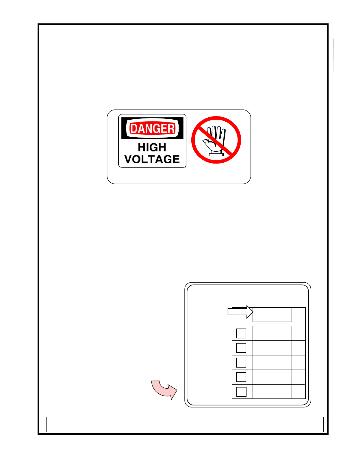
ADHERENCE TO ACCESS PROHIBITED NOTICES
Control electronics are provided in a sealed enclosure. It is imperative that only
AUTHORIZED PERSONS familiar with the working voltages and safety regulations of such
devices attempt to access the control console interior. The following label warning must be
observed and any unauthorized access immediately cancels the warranty.
OPTIONAL MAINTENANCE SCHEDULE AND INSPECTION
When your table was received we recommend that you immediately date the optional
Maintenance Schedule that may have been provided on the base. Optionally use the chart
below or make a copy to keep with your table. It is the responsibility of the user to have annual
inspections and cleaning of the table to continue the validation of the warranty. This process
includes a visual inspection of all moving components and joints and the cleaning of all patient
contact surfaces. Examine the soft control tubes leading to the hand controller for kinks or
cracks. Insure that all electrical cords are not worn or frayed. Remove any grease or soil from
surfaces that may be contacted by patient or user. Check that all fasteners
are secure. Make sure all labels are in
place and continue to be visible.
HARNESS TO HAND CONTROL
ELECTRICAL WIRING
FASTENERS
COSMETIC SURFACES
CLEAN MATS, ACCESS AREAS
LABELS IN PLACE
When the inspection is complete initial the
MAINTENANCE SCHEDULE, check the
small box and insert the inspection date.
AUTHORIZED ACCESS ONLY
Morgan MEDesign
, Inc. - Maintenance ~ Service Manual BASIC-ONE -
2005 Page 3

REMOVING PARTS
NOTE: Repair or service that involves diagnostic removal of
components violates the warranty of this equipment, unless
performed by an authorized representative of Morgan
MEDesign
, Inc. Contact Morgan MEDesign
for details,
concerns or questions.
The removal of parts within the service-able parts of this equipment requires
special consideration. Following are some guidelines.
1. Attention to cosmetic surfaces is mandatory. Be careful not to scrape or
dent any of the surfaces or finishes that appear through-out the equipment.
The attachment hardware has been selected to have nick and burr free edges
and such edges and surfaces should remain after your service. Use new
tools and handle them with care.
2. All repair or component removal is to be performed with all power
disconnected.
3. All electrical repair is to be performed by credentialed persons within the
knowledge of such repair possessing permission to proceed. High voltages
may be present and adherence to the safety warnings is mandatory. Such
repair is at the risk of the instigator and Morgan MEDesign, Inc. holds it-self
clear and harmless for actions that result during and after such procedures.
4. All removed attachments must be placed back into their original positions.
Careful mechanical detailing and matching of tolerance parts have resulted in
mandated placements that must remain after the procedure.
5. All safety labels must remain in place during and after the procedures.
Should the process destroy or deface a label a new one is to be obtained
from Morgan MEDesign, Inc.
6. Do not attempt to repair any module within this equipment that has been
manufactured by another company and used as a sub-assembly. This
includes, but is not limited to, modules built by FAIRCHILD, RENTEC,
MAGNETIC, CORCOM or other manufacturer as evidenced by their label or
logo appearing on the sub-assembly. These modules are repaired by
replacing them with another from Morgan MEDesign, Inc. Do not attempt to
contact these vendors in the service of their modules as in most cases special
versions of their product have been used in the manufacture of your
equipment and are unique to the Morgan MEDesignapplication.
Morgan MEDesign
, Inc. - Maintenance ~ Service Manual BASIC-ONE -
2005 Page 4
Morgan MEDesign
, Inc. - Maintenance ~ Service Manual BASIC-ONE -
2005 Page 5
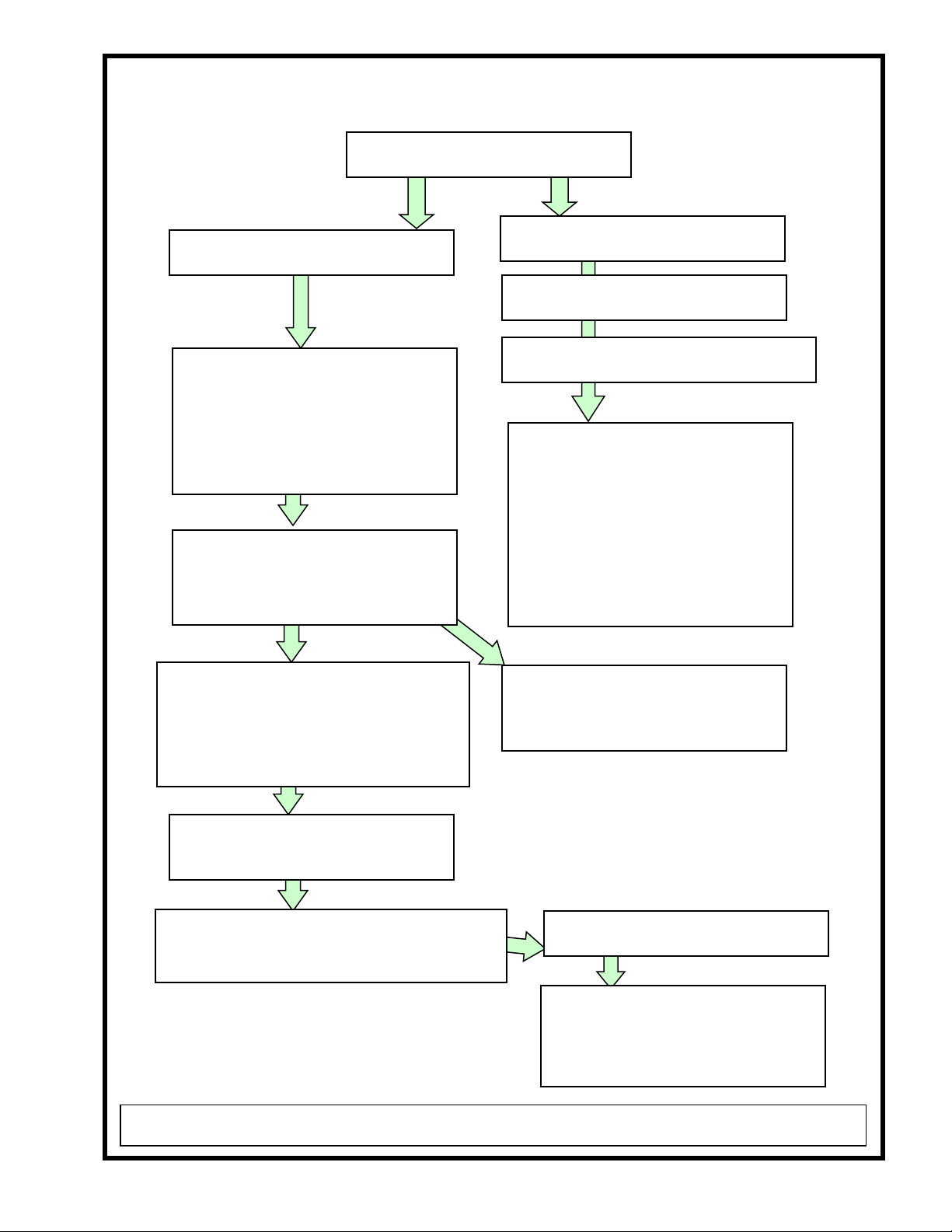
DIAGNOSTICS
NO TABLE MOVE-MENTS
GREEN STATUS LIGHT ON?
NO STATUS LIGHTS ON?
CHECK CIRCUIT BREAKER
NO TABLE MOVEMENTS ?
REPLACE AND SECURE KOM POWER
and HAND CONTROLLER CABLES
CHECK AC POWER CORD, MAINS
MONITOR CIRCUITS are O.K.
FILTER is O.K.
FAIRCHILD MONITOR is O.K.
LINE VOLTAGE is O.K.
+12 VOLT SUPPLY is O.K.
Unit is not receiving AC power
and the fault may be due to wiring
inside the base assembly. This
may been in the FILTER or at the
terminal strips. Gain access to the
inner BASE wiring and refer to
the SCHEMATIC. Establish
where power loss occurs.
CHECK KOM POWER CORD
Remove cord from KOM BOX at
connector and use volt meter to
validate AC volts on plug.
AC ABSENT = BASE wiring of
KOM POWER CORD is faulted
or terminal strip connection fault.
AC THERE = Possible KOM BOX
failure or HAND CONTROLLER
failure or loose connector at KOM
POWER CABLE or CONTROLLER
CABLE
CHECK HAND CONTROLLER
CONNECTION SECURE?
Consider replacement of KOM
POWER CONTROL BOX and
perhaps HAND CONTROLLER

Morgan MEDesign
, Inc. - Maintenance ~ Service Manual BASIC-ONE -
2005 Page 6
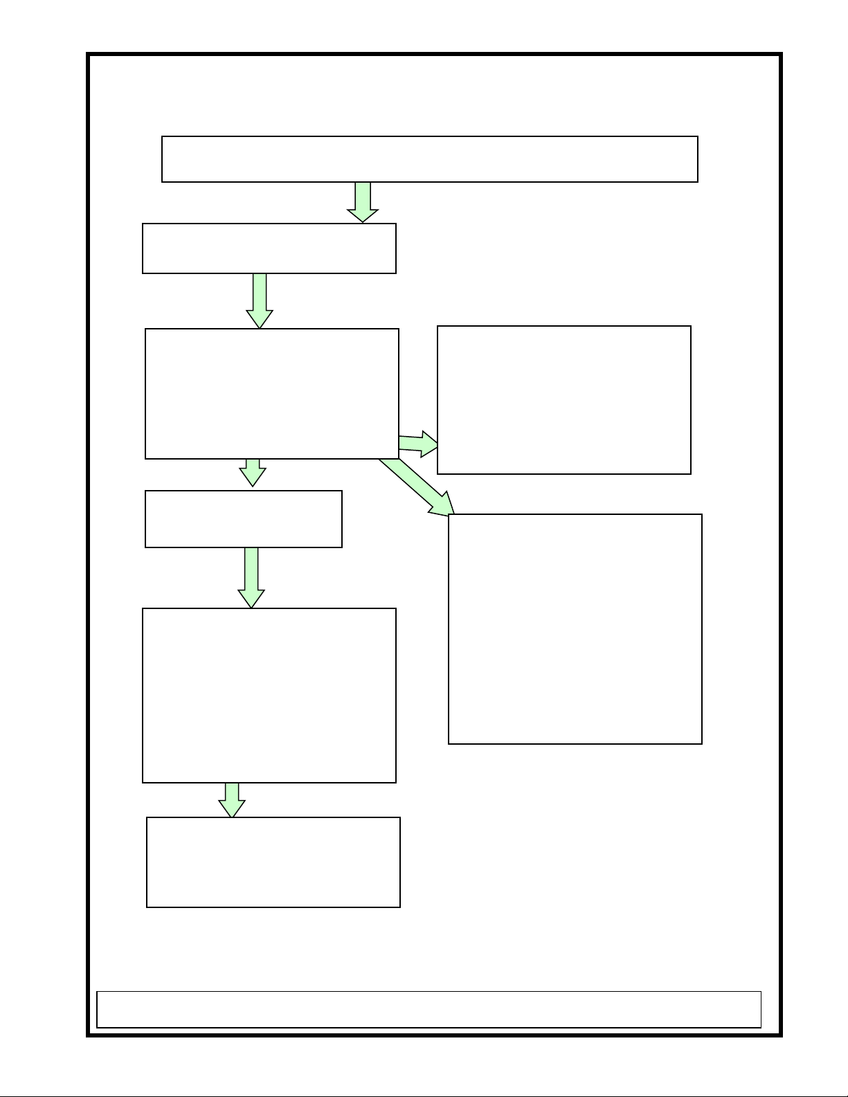
DIAGNOSTICS
PARTIAL TABLE MOVE-MENTS
GREEN STATUS LIGHT ON?
ALARM LIGHTS ON?
REPLACE AND SECURE KOM
POWER and HAND
CONTROLLER CABLE
IF PROBLEM PERSISTS-
CHECK AFFECTED MOTOR
CHECK AC MAINS
There may be weak AC voltages
present affecting the motor drives.
The STATUS lights will indicate the
voltage condition, refer to the
OPERATION MANUAL.
MONITOR CIRCUITS are O.K.
FILTER is O.K.
FAIRCHILD MONITOR is O.K.
LINE VOLTAGE is O.K.
+12 VOLT SUPPLY is O.K.
POSSIBLE OVERHEATED MOTOR
The motor drives have a duty cycle and when
this is exceeded will self-protect with a
thermal electrical breaker. WAIT 10
MINUTES and TRY OPERATION AGAIN
Possible KOM BOX failure or
HAND CONTROLLER
failure or HAND CONTROLLER
CABLE failure. Check for secure
connection.
WAIT 10 MINUTES MORE, if NO
OPERATION consider to REPLACE
the AFFECTED MOTOR
If MOTOR is O.K. consider
replacing KOM BOX or HAND
CONTROLLER
DIAGNOSTICS
ALARM STATUS LIGHT CONDITION
ALL MOTIONS WORK WELL
RE-POWER THE EQUIPMENT
Watch the STATUS lights
Do all three lights, POWER,
TROUBLE and ALARM
illuminate for 5 seconds when you
first power the equipment?
YES NO
There may be a loose or defective
bulb in the socket. The bulb that
isn’t illuminating is the culprit.
Remove the lens cap and correct
the situation which may include
bulb replacement. Look in the
OPERATION MANUAL.
CHECK AC MAINS for
under or over voltage.
AC O.K. = Possible wiring fault
in the BASE. This may also
indicate a failed RENTEC or
FAIRCHILD monitoring module.
Replacement of the MONITOR
STRIP may be necessary, the
assembly that carries both of these
modules.
Gain access to the BASE wiring.
Check all wires to and from the
RENTEC and FAIRCHILD
monitors to be secure.
Morgan MEDesign
, Inc. - Maintenance ~ Service Manual BASIC-ONE -
2005 Page 7
Gain access to the BASE wiring.
Check all wires to and from the
RENTEC and FAIRCHILD
monitors to be secure.
This may also indicate a failed
RENTEC or FAIRCHILD
monitoring module. Replacement
of the MONITOR STRIP may be
necessary, the assembly that
carries both of these modules.

DIAGNOSTICS
NOISY MOTOR
GREEN STATUS LIGHT ON?
ALARM STATUS LIGHTS ON?
Consider to
REPLACE MOTOR
CHECK AC MAINS for low voltage
MONITOR CIRCUITS are O.K.
FILTER is O.K.
FAIRCHILD MONITOR is O.K.
LINE VOLTAGE is O.K.
+12 VOLT SUPPLY is O.K.
Is the MOTOR OVERHEATED?
NO YES
WEIGHT TOO GREAT?
NO Check limits.
All MOTOR mechanical
connections secure and in place?
YES
Morgan MEDesign
, Inc. - Maintenance ~ Service Manual BASIC-ONE -
2005 Page 8
POSSIBLE OVERHEATED MOTOR
The motor drives have a duty cycle and
when this is exceeded will self-protect
with a thermal electrical breaker. WAIT
10 MINUTES and TRY OPERATION
AGAIN
WAIT 10 MINUTES MORE,
if NO OPERATION consider
to REPLACE the AFFECTED
MOTOR
Subassembly Component List –BASIC-ONE™
The following parts are used in the assembly of this equipment. Many components are
built on a custom basis and may or may not be available on a quick request. Contact
Morgan MEDesign®for the status of the desired item. Morgan MEDesign®reserves
the right to substitute or change a component or the availability of a component at any
time.
Part Number
Components Description Quantity Per
___________________________________________________________________________
BASIC ONE TABLE BASIC ONE Procedure Table
AV-PB LARGE ASSY LARGE PILLOW BLOCK 1.000
ASSEMBLY
JAR-CAS 5-50 LOCKING CASTER LOCKING 5-50MG213GD 4.000
APSL FGOALP025213GDD
MAG-EHA1321B3ON-000 6 Button Hand Control Wired 1.000
with holder * DC
MAG-KOM14020A-000 KOM BOX KOM14-020A-000 1.000
LG BOX WITH CORD 140360
HOSPITAL CORD
MAG-MAX10C100 MAX10-C100295A0A1MO-000 1.000
DC TILT 100mm stroke *LAT.
1500N
MAG-POWER CABLE DB-9 Cable * DB-9 POWER CABLE 1.000
FOR KOM BOXESWITH HUBBLE
PLUG END
MAG-TLG10AA21 2 Stage DC Lift Motor 1.000
200mm stroke 4000N *
MMI20041 BASE ASSY BASE ASSEMBLY 1.000
BASIC 1
MMI63002 Clamp Disk * 4.000
VP-20041-13 COVER-R ABS COVER RIGHT SIDE 1.000
3/16 X 35 X 11.43-BLACK
Morgan MEDesign
, Inc. - Maintenance ~ Service Manual BASIC-ONE -
2005 Page 9

Subassembly Component List –BASIC-ONE™ (continued)
VP-20041-14 COVER-L ABS LEFT SIDE COVER 1.000
3/16 X 35 X 11.438-BLACK
MMI20030-3 BASIC 1 TOP PLATE 1.000
17 X 22 ALUM PLATE
KAISER
HANDLE PUSH BAR MMI20046 HANDLE PUSH BAR 1.000
BASIC ONE -120 WALL X 1
X STEEL TUBING
MMI20042 #2 BRKT ASS #2 BRKT ASSY 1.000
BASIC ONE
MMI20043 LAT BRKT LAT BRACKET ASSY 1.000
MMI20031-4R 1.7 X 20 CLAMP BARS RIGHT 1.000
BASIC ONE
MMI20031-4L 1.7 X 20 CLAMP BARS LEFT 1.000
BASIC ONE
AV-SM/LG PB ASSY SMALL PILLOW BLOCK ASSY 1.000
MMI20044 TREN/LAT BR TREN/LAT BRACKET ASSY 1.000
GASKET-20045 MOTOR GASKET 20045 1.000
1/16 ABS PLASTIC GASKET
7.75 X 7.75 W/ 4 HOLES
MMI20047-1" RISER 1" RISER BLOCK 1.000
5.75 X 5.75 X 1"
MCM-9688K281 PLUG-NYLON SNAP IN UNVENTE 2.000
13/16 ID X 1 1/32 HEAD
MAG-MAX30A12335 CURL MAX30A120335AOA1-00-000 1.000
DC Tilt Motor, 8000N-CURLY
CORD 120mm stroke * TREND
WASHERS-20046-2 1/4 X 1.0 X 3.75 6.000
PUSH BAR WASHER FOR HANDLE
MCM-SEAL TAPE 1/2" MCM-9477K21-VALUE-SEAL 0.060
EXPANDED PIPE GASKET TAPE
MCM-74125K73 SNAP IN DUST TIGHT GRIP 1.000
FITTING 5/8 HOLE
MMI20041-DECK COVER BASIC DECK COVER FRONT & B 1.000
20041-11- & 20041-12
Morgan MEDesign
, Inc. - Maintenance ~ Service Manual BASIC-ONE -
2005 Page 10

Subassembly Component List –BASIC-ONE™ (continued)
FWS-20041-16 COVER SEAM 1/8 X 2 X 20 3/4 1.000
1/8 X 2 X 20 3/4
WHEEL ABRAIDED/ SANDBLAST
MMI20048-1 MONITOR AND STATUS ASSEMBLY 1.000
MMI20048-2 RED STATUS LIGHT ASSEMBLY 1.000
MMI20048-3 YELLOW STATUS LIGHT ASSEMBLY 1.000
MMI20048-4 GREEN STATUS LIGHT ASSEMBLY 1.000
E-20048-5 AC INPUT CORD ASSEMBLY for BASIC ONE 1.000
E-20048-6 EMERGENCY SWITCH HARNESS for BASIC NE 1.000
E-20048-7 KOM CORD HARNESS for BASIC ONE 1.000
E-ALLIED315-0009 EMERGENCY SWITCH ACTUATOR with CLAMP 1.000
E-ALLIED677-0156 CIRCUIT BREAKER, 16 amp 1.000
E-HS1138LIQTIGHT LIQUID TIGHT (LPT) 3/8 NPT Grey Pass-through 2.000
CSA-MANUAL-BASIC-OPERATING OPERATION MANUAL, BASIC-ONE 1.000
CSA-MANUAL-BASIC-MAIN + SERVICE SERVICE MANUAL, BASIC-ONE 1.000
E-ALLIED937-9615 BULBS, 6 volt, (Spare –shipped with unit) 3.000
CSA/CEKIT-MANUAL+BULB KIT, OPERATION MANUAL 1.000
plus 6 volt spare BULB
Morgan MEDesign
, Inc. - Maintenance ~ Service Manual BASIC-ONE -
2005 Page 11

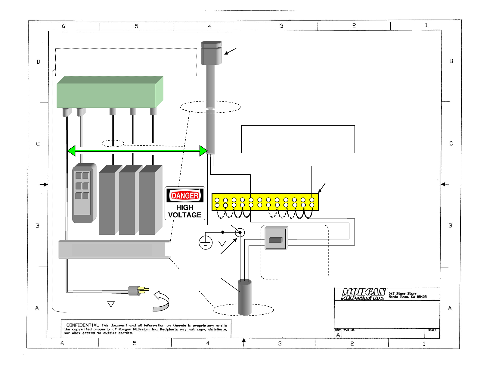
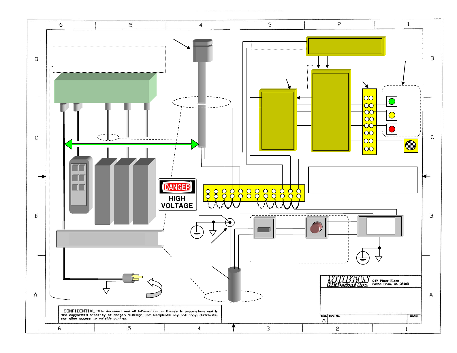
BASIC-ONE PICTORIAL PARTS
IDENTIFICATION DIAGRAM
This diagram depicts parts common to both
UL and CSA-CE versions of this equipment
Morgan MEDesign
, Inc. - Maintenance ~ Service Manual BASIC-ONE -
2005 Page 12

Morgan MEDesign
, Inc. - Maintenance ~ Service Manual BASIC-ONE -
2005 Page 13
SCHEMATICS FOR BASIC-ONE FOLLOW;
NEXT 4 PAGES
If more detail is necessary contact
Morgan MEDesign, Inc.

Schematic AC 120 V Model
BASIC-ONE –(UL- 544)
90001-01
AC INPUT
AC INPUT 120 VAC, 60 HZ
12 11 10 9 8 7 6 5 4 3 2 1
TERMINAL STRIP S1
NOTE:
MAY HAVE ANY NUMER OF
TERMINALS DEPENDING ON
APPLICATION
DUAL CIRCUIT
BREAKER 16A
ON LID COVER, BASE
POWER CABLE TO “MAGNETICS” “KOM” SERIES POWER CONTROLLER
LEGEND-
W = WHITE WIRES - NEUTRAL - COMMON
B = BLACK WIRES –HOT –ACTIVE PHASE
G = GREEN AND GROUND WIRES
BLOCK DIAGRAM
CHASSIS
CONNECTION
G B
W
W
B
HOLE IN LID
OF BASE
HOLE IN LID OF BASE
B
W
G
WITHIN BASE
LIFT MOTOR
TREND MOTOR
R/L TILT MOTOR
AC CONTROL 1 2 3
KOM CONTROLLER
IN
OUT
OUT
IN
TYPES OF KOM CONTROL UNITS
KOM 14-020A-000 5 PORT, 3 PORTS USED
KOM 33-020A-000 3 PORT, ALL PORTS USED
W
B
HOLE
MAINS, LINE IN, 3 WIRE,
PROTECTIVE GROUND
HOSPITAL GRADE
ON FRONT PANEL
Schematic AC 220 V Model
BASIC-ONE –(UL- 544)
90001-02
AC INPUT
AC INPUT 220 VAC, 60 HZ
12 11 10 9 8 7 6 5 4 3 2 1
TERMINAL STRIP S1
NOTE:
MAY HAVE ANY NUMER OF
TERMINALS DEPENDING ON
APPLICATION
DUAL CIRCUIT
BREAKER 16A
ON LID COVER, BASE
POWER CABLE TO “MAGNETICS” “KOM” SERIES POWER CONTROLLER
LEGEND-
W = WHITE WIRES - NEUTRAL - COMMON
B = BLACK WIRES –HOT –ACTIVE PHASE
G = GREEN AND GROUND WIRES
BLOCK DIAGRAM
CHASSIS
CONNECTION
G B
W
W
B
HOLE IN LID
OF BASE
HOLE IN LID OF BASE
B
W
G
WITHIN BASE
LIFT MOTOR
TREND MOTOR
R/L TILT MOTOR
AC CONTROL 1 2 3
KOM CONTROLLER
IN
OUT
OUT
IN
TYPES OF KOM CONTROL UNITS –220 V
KOM 14-020A-000 5 PORT, 3 PORTS USED
KOM 33-020A-000 3 PORT, ALL PORTS USED
W
B
HOLE
MAINS, LINE IN, 3 WIRE,
PROTECTIVE GROUND
HOSPITAL GRADE
ON FRONT PANEL
Schematic AC 120 V Model
BASIC-ONE –(UL- CSA)
90001-03
AC INPUT
AC INPUT 120 VAC, 60 HZ
12 11 10 9 8 7 6 5 4 3 2 1
TERMINAL STRIP S1
DUAL CIRCUIT
BREAKER 16A
ON LID COVER, BASE
POWER CABLE TO “MAGNETICS” “KOM” SERIES POWER CONTROLLER
LEGEND-
W = WHITE WIRES - NEUTRAL - COMMON
B = BLACK WIRES –HOT –ACTIVE PHASE
G = GREEN AND GROUND WIRES
BLOCK DIAGRAM
CHASSIS
CONNECTION
G B
W
W
B
HOLE IN LID
OF BASE
HOLE IN LID OF BASE
B
W
G
WITHIN BASE
LIFT MOTOR
TREND MOTOR
R/L TILT MOTOR
AC CONTROL 1 2 3
KOM CONTROLLER
B
IN
OUT
OUT
IN
TYPES OF KOM CONTROL UNITS
KOM 14-020A-000 5 PORT, 3 PORTS USED
KOM 33-020A-000 3 PORT, ALL PORTS USED
EMERGENCY STOP
SWITCH
LINE
FILTER
CORCOM 50-60 HZ
15EHT1
B
B
G
W
W
ALARM
TROUBLE
POWER
AUDIO
ALARM
RENTEC
STATUS
MONITOR
POW+
POW-
TROB+
TROB-
ALRM+
ALRM-
BP+
BP-
V+
NH-OK
NL-OK
NS1-OK
NS2-OK
OV
LINE
NEUT
SENS1
SENS2
0V +12V
12 POWER SUPPLY- 2 AMP
UL LISTED CSA, CE
1
2
3
4
5
6
3
4
5
6
7
8
1
2
3
4
5
6
8
10
2 1
VERSION
FOR 120V
V+5
NH-OK
NL-OK
NS1-OK
NS2-OK
OV
UL LISTED
MID400
TERMINAL STRIP
FOR WIRE ATTACH
ONLY, WIRE
COLORS ARE COLOR
OF INDICATOR
RED
BLACK
W
W
B
B
HOLE
B
W
ITEMS IN YELLOW ON SEPARATE STRIP
ON
FRONT
PANEL
MAINS, LINE IN, 3 WIRE,
PROTECTIVE GROUND
HOSPITAL GRADE
ON FRONT PANEL
MONITOR ASSEMBLY IS MMI-20048-01

Schematic AC 220 V Model
BASIC-ONE –(UL- CSA)
90001-04
AC INPUT
AC INPUT 220 VAC, 60 HZ
12 11 10 9 8 7 6 5 4 3 2 1
TERMINAL STRIP S1
DUAL CIRCUIT
BREAKER 16A
ON LID COVER, BASE
POWER CABLE TO “MAGNETICS” “KOM” SERIES POWER CONTROLLER
LEGEND-
W = WHITE WIRES - NEUTRAL - COMMON
B = BLACK WIRES –HOT –ACTIVE PHASE
G = GREEN AND GROUND WIRES
BLOCK DIAGRAM
CHASSIS
CONNECTION
G B
W
W
B
HOLE IN LID
OF BASE
HOLE IN LID OF BASE
B
W
G
WITHIN BASE
LIFT MOTOR
TREND MOTOR
R/L TILT MOTOR
AC CONTROL 1 2 3
KOM CONTROLLER
B
IN
OUT
OUT
IN
TYPES OF KOM CONTROL UNITS - 220 V
KOM 14-020A-000 5 PORT, 3 PORTS USED
KOM 33-020A-000 3 PORT, ALL PORTS USED
EMERGENCY STOP
SWITCH
LINE
FILTER
CORCOM 50-60 HZ
15EHT1
B
B
G
W
W
ALARM
TROUBLE
POWER
AUDIO
ALARM
RENTEC
STATUS
MONITOR
POW+
POW-
TROB+
TROB-
ALRM+
ALRM-
BP+
BP-
V+
NH-OK
NL-OK
NS1-OK
NS2-OK
OV
LINE
NEUT
SENS1
SENS2
0V +12V
12 POWER SUPPLY- 2 AMP
UL LISTED CSA, CE
1
2
3
4
5
6
3
4
5
6
7
8
1
2
3
4
5
6
8
10
2 1
VERSION
FOR 220V
V+5
NH-OK
NL-OK
NS1-OK
NS2-OK
OV
UL LISTED
MID400
TERMINAL STRIP
FOR WIRE ATTACH
ONLY, WIRE
COLORS ARE COLOR
OF INDICATOR
RED
BLACK
W
W
B
B
HOLE
B
W
ITEMS IN YELLOW ON SEPARATE STRIP
ON
FRONT
PANEL
MAINS, LINE IN, 3 WIRE,
PROTECTIVE GROUND
HOSPITAL GRADE
ON FRONT PANEL
MONITOR ASSEMBLY IS MMI-20048-01
Table of contents


