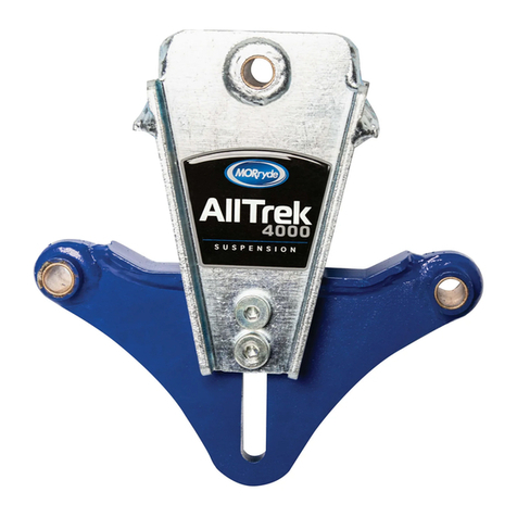
MORryde Aie1 User manual

Single Axle Air Suspension System
OWNERS MANUAL


574.293.1581
•
MORryde.com
•
PAGE 2
CONTENTS
Parts List .........................................................................................................................................................3
Parts List Assembly.....................................................................................................................................4
Introduction
• Guidelines for Adding or Removing Air Pressure...................................................................5
Pneumatic Plumbing Details...................................................................................................................6
Powerpack Details......................................................................................................................................7
Preparation
• Product and Safety Information....................................................................................................8
• Use of Manual ....................................................................................................................................9
• Compatibility.......................................................................................................................................9
• Pretravel Inspection .........................................................................................................................9
• Tow Rating Checks ............................................................................................................................9
Operating Instructions
• System Mobile App User Guide.................................................................................................10
– Remote ......................................................................................................................................... 11
– Remote Presets ........................................................................................................................ 13
– iOS App....................................................................................................................................... 13
– Android App .............................................................................................................................. 15
Maintenance ............................................................................................................................................... 18
Troubleshooting Guide
• Replacing Batteries in the Remote............................................................................................ 19
• FCC and Industry Canada Information to User ..................................................................... 19
• Error Codes......................................................................................................................................20
• Finding Air Leaks............................................................................................................................. 21
• Fixing Leaks on Barbed Fittings................................................................................................. 21
• Cutting Air Lines .............................................................................................................................. 21
• Fixing Leaks on PTC Fittings ......................................................................................................22
• Manual Control Using the Schrader Valve.............................................................................22
• Axle Thrust Adjustment................................................................................................................23
• Flat Tire Change Procedure .......................................................................................................25
• Installing Wheel Covers ................................................................................................................26
Getting Help
• YouTube Video Suggestions ...................................................................................................... 27
• Limited Warranty and Return Policy ......................................................................................... 27
• Replacement Parts Information.................................................................................................. 27
• Contact Information....................................................................................................................... 27

PARTS LIST
3/8–16
1/2–13
9/16–18
5/8–11
8
8
5
8
40
80
75
190
TORQUE CHART:
BOLT SIZE MATERIAL
GRADE PLATED
TORQUE
ft-lbs
MRA22-001
MRA35-001
CONFIDENTIAL: THE INFORMATION CONTAINED ON THIS DRAWING IS THE EXCLUSIVE PROPERTY OF
MORryde. THIS INFORMATION IS CONSIDERED AS CONFIDENTIAL INFORMATION AND SHALL NOT BE
COPIED, DUPLICATED OR SHARED WITH ANY 3RD PARTY WITHOUT WRITTEN CONSENT BY MORryde.
1 1
VARIES
VARIES
ROCKWOOD AXLE CONVERSION ASSEMBLY
daveh 10/31/2019
DRAWN: DATE:
MATERIAL:
FINISH:
TOLERANCE OF DIMENSIONS
CUST PART ID:
SHEET:
/
ALL DIMENSIONS OUTSIDE
AND IN INCHES UNLESS
NOTED OTHERWISE
X.XXXX ± 0.010
X.XXX ± 0.030
X.XX ± 0.060
ANGULAR ± 1°
Above. Beyond. Always.
MRA22-001-Part Call Outs
PART
CLASS
B
PARTS LIST
PART NUMBERQTYITEM
TRAILING ARM - LH11
TRAILING ARM - RH12
ROCKWOOD AXLE BY DEXTER
13
SPRING CARRIER LH
14
TRAILING ARM BRACE
45
BOLT 1/2"-13 X 1-1/4" 96
U-BOLT 9/16-1867
BOLT 5/8"-11 X 5-1/2" 28
5/8"-11 LOCK NUT29
PIVOT BRKT. X-MEMBER110
FLANGE WHIZ NUT 3/8"-16411
U-BOLT LOCK NUT 9/16"-18 1212
UPPER SHOCK MOUNT BOLT213
BOLT 3/8"-16 X 1" 414
AIR SPRING215
PIVOT BOLT WASHER
416
LOOP SHOCK
217
PIVOT BRACKET - RH
118
PIVOT BRACKET - LH119
SPRING CARRIER - RH120
AIR SPRING BOLT 10X1.5X25421
LOCK NUT 1/2"-13
423
FLAT WASHER 1/2"
224
BOLT 1/2"-13 X 3-1/2"225
FLANGE WHIZ NUT 1/2"-13 1326
SCHRADER VALVE UO136-3236127
1/4" UNION ELBOW UO135-3238128
STREET T UO135-3239129
1/4" NYLON AIR HOSE UO136-3235130
UNION T UO136-3237131
PINCH POINT DECAL UO162-063
232
RIDE HEIGHT DECAL UO162-061
133
RIDE HEIGHT DECAL UO162-062
134
DATE REV DESCRIPTIONINIT
REVISION HISTORY
4
10
13 1
10/03/19 A DEH PRODUCTION RELEASE
19
11
19
15 34
3
7
9
23
13
6
31
27
33
32
5
2
23
25
17
6
8
11
14
15
24
18
20
26 29
CONFIDENTIAL: THE INFORMATION CONTAINED ON THIS DRAWING IS THE EXCLUSIVE PROPERTY OF
MORryde. THIS INFORMATION IS CONSIDERED AS CONFIDENTIAL INFORMATION AND SHALL NOT BE
COPIED, DUPLICATED OR SHARED WITH ANY 3RD PARTY WITHOUT WRITTEN CONSENT BY MORryde.
1 1
VARIES
VARIES
ROCKWOOD SINGLE AXLE AIR SUSPENSION
daveh 10/31/2019
DRAWN: DATE:
MATERIAL:
FINISH:
TOLERANCE OF DIMENSIONS
CUST PART ID:
SHEET:
/
ALL DIMENSIONS OUTSIDE
AND IN INCHES UNLESS
NOTED OTHERWISE
X.XXXX ± 0.010
X.XXX ± 0.030
X.XX ± 0.060
ANGULAR ± 1°
Above. Beyond. Always.
MRA35-001-Part Call Outs
PART
CLASS
B
PARTS LIST
PART NUMBERQTYITEM
WHIZ NUT 1/2"-13
221
FLANGE BOLT 1/2"-13 X 1-1/4"
222
FRAME HANGER CAPTURE PLATE- LH
13
FRAME HANGER CAPTURE PLATE- RH14
MRA136-004; POWERPACK-V215
MRA136-005; FOB16
UO136-3235-130 INCHES
17
DATE REV DESCRIPTIONINIT
REVISION HISTORY
2
1
5
7
6
6
6
FRAME RAILS ARE
NOT A PART OF MRA35-001
2
2
10/31/19 A DEH PRODUCTION RELEASE
3
574.293.1581
•
MORryde.com
•
PAGE 4
PARTS LIST ASSEMBLY
MRA22-001
MRA35-001
CONFIDENTIAL: THE INFORMATION CONTAINED ON THIS DRAWING IS THE EXCLUSIVE PROPERTY OF
MORryde. THIS INFORMATION IS CONSIDERED AS CONFIDENTIAL INFORMATION AND SHALL NOT BE
COPIED, DUPLICATED OR SHARED WITH ANY 3RD PARTY WITHOUT WRITTEN CONSENT BY MORryde.
1 1
VARIES
VARIES
ROCKWOOD AXLE CONVERSION ASSEMBLY
daveh 10/31/2019
DRAWN: DATE:
MATERIAL:
FINISH:
TOLERANCE OF DIMENSIONS
CUST PART ID:
SHEET:
/
ALL DIMENSIONS OUTSIDE
AND IN INCHES UNLESS
NOTED OTHERWISE
X.XXXX ± 0.010
X.XXX ± 0.030
X.XX ± 0.060
ANGULAR ± 1°
Above. Beyond. Always.
MRA22-001-Part Call Outs
PART
CLASS
B
PARTS LIST
PART NUMBERQTYITEM
TRAILING ARM - LH11
TRAILING ARM - RH12
ROCKWOOD AXLE BY DEXTER
13
SPRING CARRIER LH
14
TRAILING ARM BRACE
45
BOLT 1/2"-13 X 1-1/4" 96
U-BOLT 9/16-1867
BOLT 5/8"-11 X 5-1/2" 28
5/8"-11 LOCK NUT29
PIVOT BRKT. X-MEMBER110
FLANGE WHIZ NUT 3/8"-16411
U-BOLT LOCK NUT 9/16"-18 1212
UPPER SHOCK MOUNT BOLT213
BOLT 3/8"-16 X 1" 414
AIR SPRING215
PIVOT BOLT WASHER
416
LOOP SHOCK
217
PIVOT BRACKET - RH
118
PIVOT BRACKET - LH119
SPRING CARRIER - RH120
AIR SPRING BOLT 10X1.5X25421
LOCK NUT 1/2"-13
423
FLAT WASHER 1/2"
224
BOLT 1/2"-13 X 3-1/2"225
FLANGE WHIZ NUT 1/2"-13 1326
SCHRADER VALVE UO136-3236127
1/4" UNION ELBOW UO135-3238128
STREET T UO135-3239129
1/4" NYLON AIR HOSE UO136-3235130
UNION T UO136-3237131
PINCH POINT DECAL UO162-063
232
RIDE HEIGHT DECAL UO162-061
133
RIDE HEIGHT DECAL UO162-062
134
DATE REV DESCRIPTIONINIT
REVISION HISTORY
4
10
13 1
10/03/19 A DEH PRODUCTION RELEASE
19
11
19
15 34
3
7
9
23
13
6
31
27
33
32
5
2
23
25
17
6
8
11
14
15
24
18
20
26 29

INTRODUCTION
Guidelines for Adding or
Removing Air Pressure
When preparing to head out for a
drive, make sure the suspension height
indicators are in the green zone. Use your
remote, mobile app, or Schrader valve to
add or remove air as needed.
When loading or unloading a vehicle
into the garage of the trailer, it is
recommended to kneel the trailer
by exhausting air spring pressure to
approximately 5 PSI.
Increase air pressure in the system to
overcome temporary obstacles and raise
ground clearance.
The MORryde Air1 system controls air suspension height on your trailer using a remote and/or a mobile app to control air
pressure. There are three main components to this system:
Suspension Height Indicator
The suspension height indicator makes sure the trailer is
operating within safe pressure and height zones. This is
located on both sides of the air suspension in front of the
tire (fig. A). The suspension height indicator points on and
around a labeled green zone. When adjusting pressure
in the system before towing the trailer, check that the
indicators point in the green zone.
NOTE: If you lose power, use an external air source to inflate
the air suspension through the Schrader valve, indicated in
(fig. A) This method can also be used to exhaust and kneel
the trailer.
Suspension
Height Indicator
Green Zone
figure A
WARNING
Only tow the trailer when the suspension height indicators
are in the green zone. Check the indicators and adjust air
pressure as needed before towing the trailer.
Powerpack
The powerpack communicates wirelessly with the remote and mobile
app to control the air pressure in your suspension. It includes the
module and compressor and is located on the front crossmember
between the A-Arms and behind the battery of the trailer.
Remote and/or Mobile App
Use the remote and/or mobile app to increase or decrease
pressure and otherwise control and troubleshoot the MORryde
Air1 system.
Schrader Valve
1
2
3

574.293.1581
•
MORryde.com
•
Suspension Plumbing
PNEUMATIC PLUMBING DETAILS
Air Hose Line Location: Underneath Unit View
Air Hose to
Roadside Air Spring
Union T — This may also be replaced
with a Street T on the Curbside Air Spring
Air Hose to Curbside
Air Spring
From Compressor Union T To Air Spring
PAGE 6

Plumbing and Electrical
Air Filter
One-Way
Check Valve
Electrical
Connection
to Module
Air Compressor
Air Intake Hose
Air Outlet to Module
Powerpack: Back View
POWERPACK DETAILS
Powerpack: Front View
Air Spring Supply
Pressure
Control
Module
Power Supply Wire
(20 amp fuse protectant required)
Chassis Ground Wire

574.293.1581
•
MORryde.com
•
PAGE 8
PREPARATION
Failure to follow the instructions and heed the
warnings of this manual may result in death or serious
injury, damage to the vehicle and/or trailer, and/
or voidance of the product warranty. Always utilize
appropriate personal safety equipment, i.e. proper
eye protection, hearing protection, gloves, etc.
When working under the trailer, adequately support
the unit at the trailer frame and deploy the stabilizer
jacks. Do NOT kneel the trailer when working under
it. Securely block all trailer wheels when the unit is
disconnected from the towing vehicle. All work should
be done on level ground.
WARNING
WARNING
WARNING
WARNING
PINCH POINT: Keep hands
away. Moving suspension may
cause serious injury.
See Owners Manual for service.
Never kneel or raise the trailer when the
StepAbove™ Steps are deployed due to risk of
property damage and/or personal injury.
Don't place hands in this area
Product and Safety Information
The powerpack is attached onto the
front crossmember located between
the A-Arms, behind the battery.

Follow all hitching and towing specifications of
the trailer and towing equipment manufacturers.
You are personally responsible for safe hitching
and unhitching, loading and unloading, and
towing and driving practices.
Tow Rating Checks
Failure to verify and follow tow ratings may
result in damage to the tow vehicle or trailer
during transit. The trailer and its contents must
not exceed truck, hitch, and/or trailer tow ratings.
Do NOT Exceed
• Towing vehicle manufacturer's ratings
• Hitch manufacturer's ratings
• Trailer manufacturer's ratings
• Trailer coupler manufacturer's ratings
WARNING
Follow all trailer manufacturer’s specifications for
safe loading/unloading of trailer.
WARNING
Use of Manual
Dealer
• Provide Manual to end user
End User
• Read and follow Manual with each use of the
MORryde Air1 Suspension System
• Save Manual for future reference
• Provide Manual to other users or future owners of
the MORryde Air1 Suspension System
Failure to follow all of these instructions may result in
serious injury or death.
Compatibility
• The system uses a 12v compressor. Contact
MORryde for correct replacement if necessary.
• Use the correct size ball for the trailer coupler and
prior to hitching and towing, ensure compatibility.
Pretravel Inspection
Prior to each tow, complete a pretravel inspection and
walk-around of the trailer and towing equipment.
• Inspect the condition of all towing equipment.
Make any repairs or replacements necessary.
• Inspect the condition and torque of all bolts.
• Check that the suspension height indicator is in the
green zone on both sides of the trailer.
WARNING
WARNING

System Mobile App
USER GUIDE
574.293.1581
•
MORryde.com
•
PAGE 10

REMOTE
Operation
STEP 1
Push a button to wake up the remote, which will
display the target pressure.
STEP 2
Press the up/down arrows to raise/lower the
pressure in increments of 1 PSI (0.1 BAR).
NOTE: Maximum pressure is 80 PSI (5.5 BAR).
NOTE: To enter the menu, press the inflate and
deflate buttons at the same time (fig. 1).
Backlight
The remote display stays on for 40 seconds.
The backlight automatically dims after 2 to 10
seconds depending on battery condition, then
goes o after an additional 30 seconds. Press
any button to wake up the remote.
figure 1
Up arrow / Inflate
Down arrow / Deflate
Bluetooth signal strength
indicator and connection status
indicator
Indicates preset;
no preset indicated when
pressure is set manually
•• (P2)
• (P1)
Battery life indicator
(indicates full or low)
Air pressure setting (PSI
or BAR)
Indicates when the system is
inflating or deflating
Max. Pressure: Min. Pressure:
80 PSI (5.5 BAR) 5 PSI (0.34 BAR)

574.293.1581
•
MORryde.com
•
PAGE 12
figure 4
STEP 3
Use the up and down arrows to choose the module.
Press • (P1) to begin pairing process.
STEP 4
The device will indicate “pairing” when it is connecting
to a device. There is no Bluetooth password.
STEP 5
Once complete, the remote will either indicate “pairing
successful” which means the devices are paired, or
“pairing unsuccessful” which will require the user to pull
and reinstall the fuse and try again. Once the remote is
connected to the module, it will automatically connect
each time the module is active and the remote is
woken up.
NOTE: To enter the menu, press the inflate and
deflate buttons at the same time (fig. 1).
Units
Select "Units" from the menu to switch between PSI
and BAR (fig. 4). The factory default is PSI.
Troubleshoot
Select "Troubleshoot" from the menu to see system
error messages. For more information about error
messages, review the section in this manual called
Troubleshooting Guide.
Pair the Module to the Remote
The module will enter pairing mode for three
minutes after the fuse is installed. Once a device
is paired, it will automatically connect if no other
device is already connected. The remote will go
into sleep mode after 40 seconds, at which time it
will disconnect from the system.
NOTE: The remote comes with batteries installed.
To operate the device, slowly pull the tab out of
the battery compartment.
STEP 1
To initiate pairing mode, remove the fuse, wait five
seconds, and reinstall.
STEP 2
Press a button to wake up the remote. It will
automatically go to the pairing screen if it is not
already paired with a module. Use the up and down
arrow buttons to navigate the pairing menu. Select
the device that matches the module serial number
(figs. 2 & 3).
figure 2
figure 3

REMOTE PRESETS
IOS APP
STEP 1
Set the pressure to the desired level using the inflate and deflate
buttons (fig. 5).
STEP 2
To set each preset:
Preset 1: Press and hold the • (P1) for 3 seconds.
Preset 2: Press and hold •• (P2) for 3 seconds.
Preset 3: Push and hold the • and •• buttons simultaneously
for 3 seconds.
As an example, after setting the desired pressure, press and
hold • to set preset 1.
NOTE: The remote indicates which preset is currently selected
in the lower left corner.
User Interface Operation
STEP 1
Open the app to the user interface. It shows the desired pressure (fig. 6).
STEP 2
Press the up/down arrows to inflate/deflate in increments of 1 PSI (0.1 BAR).
STEP 3
Click on the gear by each preset to set and name the presets.
STEP 4
Click on the air pressure number to manually enter a desired pressure.
Up arrow / Inflate
•• (P2)
• (P1)
Down arrow / Deflate
Menu
Connection
status
Inflate
Pressure setting
(PSI or BAR)
Deflate
Presets
figure 5
figure 6
Max. Pressure: Min. Pressure:
80 PSI (5.5 BAR) 5 PSI (0.34 BAR)

574.293.1581
•
MORryde.com
•
PAGE 14
Pair the Module to the Mobile App
STEP 1
Download the free MORryde Air1 app from the Apple App Store for iOS. Search for
MORryde Air1.
STEP 2
Put the module in pairing mode by removing the fuse to the battery and replacing it
after five seconds. The module will remain in pairing mode for three minutes after the
fuse is reinstalled.
STEP 3
The app will automatically go to the "Devices" screen if no connected module is
detected. Click on the device you want to pair. The module will have MORryde Air1 in
the title. Each device also shows the connection status (fig. 7).
NOTE: Once the mobile app is paired to the module via Bluetooth, it will connect
automatically each time the module is active and the device is in range. Only one device
can be connected at a time. To connect another device, the app on any device currently
connected must be closed.
Settings
STEP 1
Open the "Settings" screen (fig. 8) to view these options:
Devices
• Lists modules that are within range.
Troubleshoot
• Displays system error messages
(See Troubleshooting Guide section)
Settings
• Pressure control units (PSI or BAR)
• Prevent Screen Lock stops the mobile device screen
from going to sleep while the app is open
Firmware Update
Communicate
• Online Help
- Links to morryde.com
• About (fig. 9)
- Shows app software revision and module firmware revision
figure 7
figure 8 figure 9
STEP 4
To pair a second mobile device, repeat the procedure on that device. The module can pair with up to 10
mobile devices. One mobile device can pair with any number of modules; there is no limit.
STEP 2
Use the “Done” button to go back to the user interface.

App Presets
STEP 1
Connect the app to the module to change presets (fig. 10).
The presets are stored on the module, so changes made
in the app will also aect the remote and vice versa.
STEP 2
Adjust the presets by clicking on the gear by each preset.
STEP 3
To adjust preset values, click on the name or pressure
value and type the desired name and pressure.
STEP 4
Click “OK” to save the preset or “Cancel” to close the
preset screen.
figure 10 figure 11
Firmware Update
STEP 1
Connect the app to the module to change firmware on
the module (fig. 11).
STEP 2
Update MORryde Air1 app to download the latest firmware for transfer to the module.
ANDROID APP
Dashboard Operation
STEP 1
Open the app to the dashboard. It shows the desired pressure (fig. 12).
STEP 2
Press the up/down arrows to inflate/deflate in increments of 1 PSI (0.1 BAR).
STEP 3
Click on the gear by each preset to set and name presets.
STEP 4
Click on the air pressure number to manually enter a desired pressure.
figure 12
Menu
Connection
status
Inflate
Pressure setting
(PSI or BAR)
Deflate
Presets
Max. Pressure: Min. Pressure:
80 PSI (5.5 BAR) 5 PSI (0.34 BAR)

574.293.1581
•
MORryde.com
•
PAGE 16
Navigation/Communicate
STEP 1
Open the "Navigation/Communicate" screen (fig. 14)
to view these options:
Navigation
• Dashboard
- Closes the menu and returns to the dashboard
• Devices
- Lists devices that are available for pairing
• Troubleshoot
- Displays system error messages
(See Troubleshooting Guide)
• Settings
- Pressure control units (PSI or BAR)
- Prevent Screen Lock stops the mobile device screen
from going to sleep while the app is open
• Update Firmware
Pair the Module to the Mobile App
STEP 1
Download the free MORryde Air1 app from Google Play for Android. Search for
MORryde Air1.
STEP 2
Put the module in pairing mode by removing the fuse to the battery and replacing
it after five seconds. The module will remain in pairing mode for three minutes after
the fuse is reinstalled.
STEP 3
The app will automatically go to the "Devices" screen if no connected module is
detected. Click on the device you want to pair. The module will have MORryde Air1
in the title. Each device also shows the connection status (fig. 13).
NOTE: Once the mobile app is paired to the module via Bluetooth, it will connect
automatically each time the module is active and the device is in range. Only one
device can be connected at a time. To connect another device, the app on any
device currently connected must be closed.
figure 13
STEP 5
To pair a second mobile device, repeat the procedure on that device. The module can pair with up to
10 mobile devices. One mobile device can pair with any number of modules; there is no limit.
figure 14 figure 15

App Presets
STEP 1
Connect the app to module to change presets (fig. 16).
The presets are stored on the module, so changes made
in the app will also aect the remote and vice versa.
STEP 2
Adjust the presets by clicking on the gear by each preset.
STEP 3
To adjust preset values, click on the name or pressure
value and type the desired name and pressure.
STEP 4
Click “ACCEPT” to save the preset or “CANCEL” to close
the preset screen.
Firmware Updates
STEP 1
Connect the app to the module to change firmware on the module (fig. 17).
STEP 2
Update the MORryde Air1 app to download the latest firmware for transfer to the module.
figure 16 figure 17
Communicate
• Online elp
- Links to morryde.com
• About (fig. 15)
- Shows app software revision and module firmware revision
STEP 2
Click o of the menu bar or press the back button to return to the dashboard.

574.293.1581
•
MORryde.com
•
PAGE 18
TROUBLESHOOTING GUIDE
For any issue not listed, contact MORryde Customer Service
at 574.293.1581 or [email protected].
Error codes are labeled “Active Errors” and “Dormant Errors”
on the app (fig. 20). Active and dormant error codes are
indicated by “A” and “D” on the remote (fig. 21).
Use the “CLEAR ERRORS” button to clear current codes and
check for presently active codes. Error codes can only be
cleared by using the mobile app.
Example of error code on the smartphone
app for iOS (left) and Android (right).
figure 20
figure 18
figure 19
Example of an error
code on the remote.
figure 21
MAINTENANCE
• Follow all truck, hitch, coupler, trailer, and axle manufacturers’
preventive maintenance recommendations.
• Repaint metal suspension components to prevent rust and
maintain its appearance.
NOTE: Do NOT paint over labels.
• Periodically check the torque values of all hardware. Torque
specifications have been provided on (pg. 3) of this manual.
Cold Weather Service
It’s possible that the valve may freeze when operating in cold weather.
A hair dryer can be used to thaw the check valve, see (fig. 18). Injecting
airline antifreeze such as ABC Air Brake Conditioner into the system
can also be used to thaw the check valve, see (fig. 19). If the trailer
is going to be used frequently in cold weather, contact MORryde
International for a Cold Weather Kit that can be added to your Single
Axle Air Suspension.

FCC and Industry Canada Information to User
This device complies with Part 15 of the FCC Rules and with Industry
Canada license-exempt RSS standard(s). Operation is subject to
the following two conditions: (1) This device may not cause harmful
interference, and (2) This device must accept any interference
received, including interference that may cause undesired operation.
Le présent appareil est conforme aux CNR d’Industrie Canada
applicables aux appareils radio exempts de licence. L’exploitation
est autorisée aux deux conditions suivantes : (1) l’appareil ne doit pas
produire de brouillage, et (2) l’utilisateur de l’appareil doit accepter
tout brouillage radioélectrique subi, même si le brouillage est
susceptible d’en compromettre le fonctionnement.
REMOTE
FCC ID: 2ANLC-OMQ22817
IC: 23130-OMQ22817
MODULE
FCC ID: 2ANLC-HJL71117
IC: 23130-HJL71117
NOTE: Changes or modifications not expressly approved by the party responsible for
compliance could void the user’s authority to operate the equipment.
Replacing the Batteries in the Remote
STEP 1
To install the two CR2032 batteries in the remote, use a small flat screwdriver to separate the two
halves of the remote by prying apart the internal clip locations.
STEP 2
Stack the batteries positive to negative inside the rear cover with the positive end pointed in the
direction of the circuit board. Take note of “NEG” on the case and “+” symbol on the circuit board.
STEP 3
Snap the front cover/circuit board onto the rear cover.
Internal clips Positive
Negative
Table of contents
Other MORryde Automobile Accessories manuals
Popular Automobile Accessories manuals by other brands

Sune Technology
Sune Technology SUNE10-NTG55 installation manual

PE Racing
PE Racing Pedalbox Assembly Manual & Installation Instructions

Peiker Acustic
Peiker Acustic Bluetouch Music operating manual

Safe Fleet
Safe Fleet RVS installation guide

LAS
LAS 10332 operating instructions

Aries
Aries S224046 installation manual

Whispbar
Whispbar K392W Fitting Instructions for Basic Carrier

Rola
Rola PMX169 Fitting instructions

Targus
Targus APD046EU quick start

Offroad Animal
Offroad Animal PR-JGC-WK2-11-ASM0 FITTING INSTRUCTION

Fiamma
Fiamma 08753-01 Installation and usage instructions

Safe Fleet
Safe Fleet Prime Design UVX-211 manual