TOOLS REQUIRED:
Torque Wrench • Floor Jacks • Safety Stands • 1/2" Socket • 1/2"
Wrench • 9/16" Socket • 9/16" Wrench • 11/16" Socket • 13/16"
Wrench • Hammer • Ratchet
PARTS LIST:
• See Page 7
AFTERMARKET TRIPLE INSTALLATION INSTRUCTIONS
Step 1
Loosen all lug nuts. Using appropriately rated jacks, raise
the unit and support the frame with safety stands. Support
the axles with floor jacks and remove all wheels.
Step 2
On the curbside of the unit, use an 11/16" socket and 13/16"
wrench and remove the shackle links from the front leaf
spring, remove the shoulder bolt from the center leaf
spring, and then remove the shoulder bolt from the top of
the equalizer.
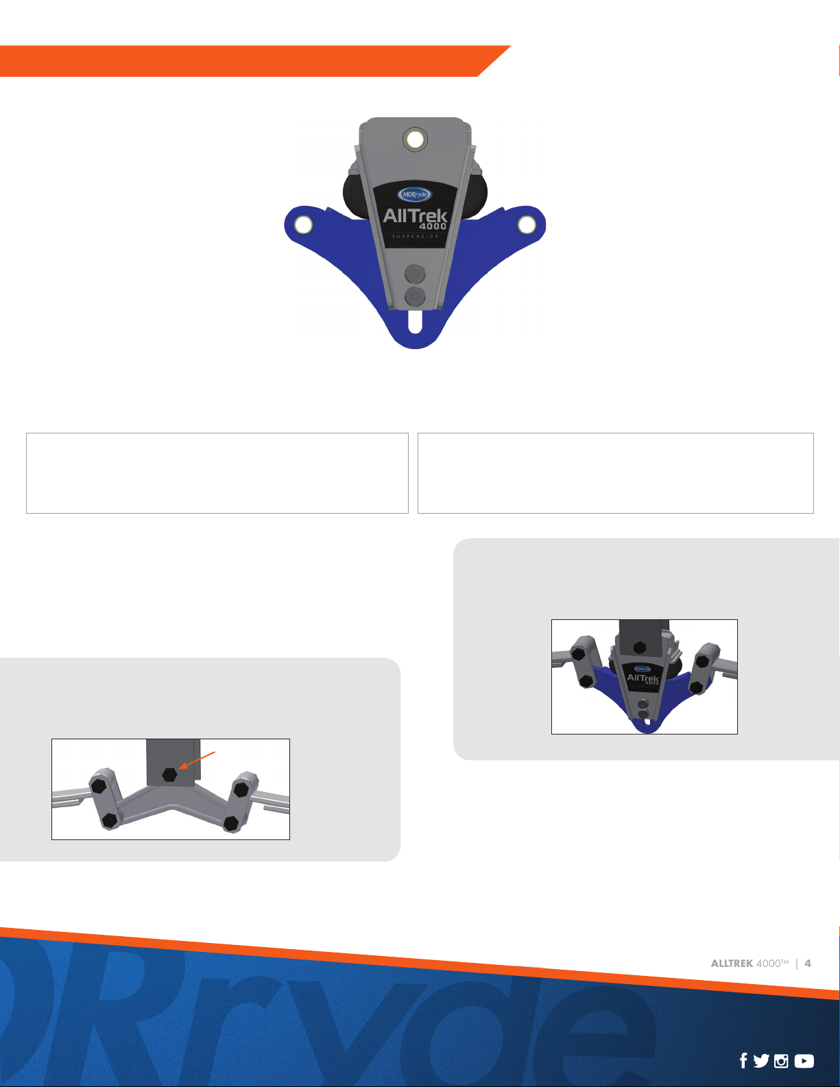
INSTALLATION:
1
st
3
rd
2
nd
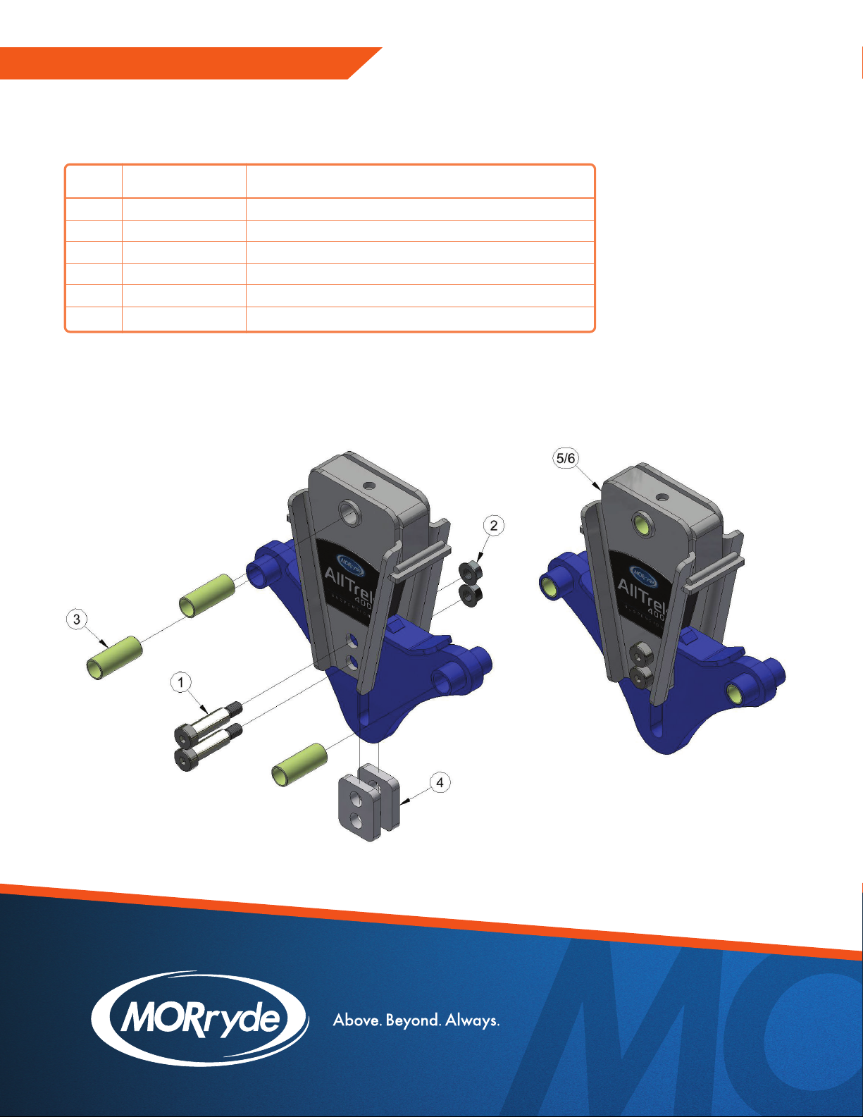
Step 3
Replace the equalizer with the AllTrek 4000™ using one
of the 3.4" long wet bolts (shoulder bolt with grease jerk)
included in the installation kit. The threaded end of the bolt
will face the inside of the trailer. Slide the Outer Torque
Cross Member (cross member with slots and ears) onto
the end of the bolt, then install the 7/16-20 Flange Locknut.
Reinstall the front shackle links and install a new Shackle
Link Assembly and loose Shackle Link along with the 7/16-
20 Flange Locknuts. Do not torque any of the nuts.
NOTE: Use a hammer to pound the wet bolts into the frame hangers. Use
a pipe or small diameter socket to fit over the grease zerk and pound the
bolt in place (it is important not to damage the grease zerk) or remove the
zerk, pound the bolt in place, and reinstall the zerk. Make sure the grease
exit hole in the shoulder of the bolt faces to the side for easy grease flow.
Step 4
Remove the floor jack from the front axle and use it to
support the rear axle. Then, remove the shackle links
from the rear equalizer, then remove the shoulder bolt.
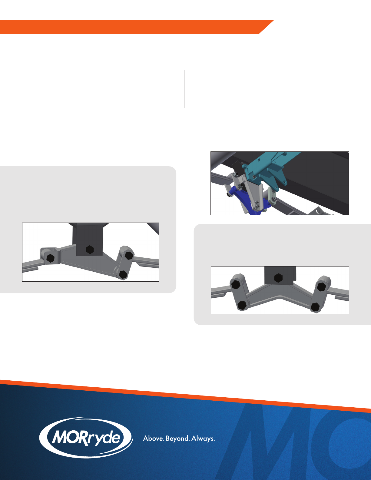
Step 3
Step 5
Replace the stock equalizer with the AllTrek 4000™
using one of the 3.4" long wet bolts. The threaded end
of the bolt will face the inside of the trailer. Slide the
Inner Cross Member (cross member with holes) onto the
end of the bolt, then install the 7/16-20 Flange Locknut.
Reinstall the shackle links.
* Triple axle AllTrek 4000™ cannot be used with Correct Track.
* Triple axle AllTrek 4000™ cannot have items hanging down under the frame between the equalizer hangers.