Mortara Instrument Quinton Q-Stress 4.5 User manual

1
Q-Stress 4.5
System Installation Instructions
REF: 70-00261-02 Rev D1
Copyright © 2014 Mortara Instrument, Inc. All rights reserved.
Contents
3epocS
4snoitcennocerawdraH
7tracssertsanonoitallatsnimetsyS
8thgiehecafruspotfotnemtsujdA
Install the writing surface and paper tray 10
11tnemecalptnenopmoC
71eciveDesicrexEehttcennoC

2
Mortara Instrument, Inc. 7865 North 86th Street, Milwaukee, WI 53224 U.S.A. • Tel: 1.800.231.7437 • Fax: 1.414.354.4760 • Website: www.mortara.com
Technical Support: Tel: 1.888.667.8272 • Email: techsupport@mortara.com
Manufactured By: Mortara Instrument, Inc.
Mortara, Q-Exchange, and Quinton
are trademarks of Mortara Instrument, Inc.
Copyright ©2014 Mortara Instrument, Inc.
All Rights Reserved.
Information in this document issubject to change without notice. Names and data used in
the examples are fictitious unless otherwise noted.
CE Mark Declaration
e CE markingofconformity indicatesthat the device having this symbol on its
immediate label meets the applicable requirements of the European Medical Device
Directive.
Trademark Information
Quinton, Burdick, HeartCentrix‚ Q-Stress, and HeartStride are trademarks or registered
trademarks of Mortara Instrument, Inc. All other product and company names are trademarks
or registered trademarks of their respective companies.
Copyright ©2014 Mortara Instrument, Inc. All Rights Reserved.

3
Scope
Scope
is document describes the assembly of a Stress system. It is designed to be used as a
whole for the installation process or in part as a troubleshooting tool for ensuring correct
connection, configuration, and functioning of the Stress system.
Because the Stress system can be purchased in different configurations and with different
options, your system’s feature set may be different from the feature set shown in this
document.
Read all instructions before you begin the installation process. Follow the instructions in
the order given.
If you have any questions regarding execution of these instructions, contact technical
support at:
1.888.667.8272
techs[email protected]

4
Q-Stress 4.5 System Installation Instructions
Hardware connections
!
Caution. The following cautions apply:
The computer, monitor, preamp, and printer must be plugged into the isolation transformer.
The preamp and printer must be plugged into the A outlets and the computer and monitor
(or computer and power strip on units equipped with the optional external hard disk) must
be plugged into the B outlets.
*Connect the optional external hard drive to the Stress system using a power strip. Refer to
the instructions provided with the external hard drive for proper connection.
*Do not plug any other components into the power strip on units equipped with the optional
external hard disk.
The isolation transformer must be plugged into a dedicated circuit.
The treadmill must be plugged into a dedicated circuit.
*You cannot connect both a laser printer and an optional external hard drive on the same
system.
If the preamp is mounted on the treadmill handrail, it should be mounted perpendicular to
the treadmill belt to avoid damaging the unit when the treadmill is inclined.
Use of an uninterruptable power supply (optional)
If you use an uninterruptable power supply (UPS), insert it between the isolation
transformer and the computer and monitor. See the system configuration block diagram
(Figure 1).
!
WARNING! Electronic interference.
The preamp can be mounted on the treadmill handrail, placed on the oor, or located in
another convenient spot. It should be installed in a location that removes the patient cable
from close proximity to power cords, transformers, or other power lines connected devices
to minimize noise pick-up.
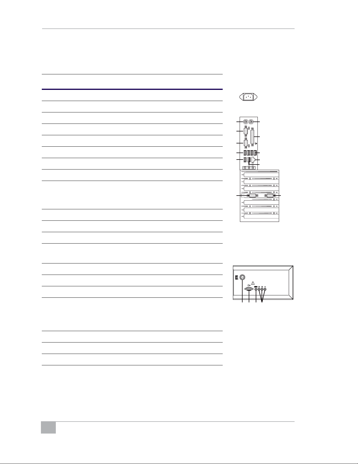
System conguration
e block diagram (Figure 1) shows a typical configuration and suggested locations for
plugging in the various system hardware components. Your system will be similar but may
not be identical to the configuration shown. If you have questions about connecting
components, contact technical support.
!
WARNING! Electronic interference.
Grounding reliability can be achieved only when equipment is connected to a properly-
grounded receptacle. Ensure that the isolation transformer is connected to this type of
electrical outlet.

5
Hardware connections
Figure 1: Stress system components
Note: There is a power switch on the front of the computer that must be pressed to boot up
the computer. Turn o the computer by shutting down Windows.
Use the QRS Sync to connect a blood pressure monitor to the system (rather than one of the
Analog Outputs).
Make a note of which ports are used to connect the treadmill, ergometer, and blood pressure
monitor. You will need this information to congure the Stress software.
Attach the service card and plastic sleeve to the video cable using the supplied wire ties.
The HASP® (or dongle) attaches to the computer’s parallel port.
!
Caution. Improper voltage.
The ergometer exercise device may not be self switching. Refer to the ergometer user guide
for proper voltage adjustment setting.
Computer
Remote
Keypad
(Optional)
Keyboard
Mouse
USB
PS2
Treadmill
USB
RS-232
RS-232
USB
QRS Synch
Patient
Cable
Power
Data
AC Wall
LCD
Laser Printer
Preamp II
Blood
AC Wall
Outlet Outlet
Pressure
Monitor
Isolation
Transformer
ParallelChart Recorder
USB
COM 1
Preamp II
supply
Power
B
A
A
Uninterruptable
Power Supply
(optional)
Monitor
!
Caution. Treadmill communication.
Power Management should be disabled for USB ports to prevent USB ports from being
powered down. This is benecial for maintaining communication with the treadmill.
To congure Q-Stress with USB power management disabled, select Power Options, then
Advanced settings, then USB settings and set USB selective suspend setting = Disabled.
Table of contents