Mortara Instrument X-Scribe User manual

MIS-11-151-01 Rev 9 CONFIDENTIAL Page 1 of 22
Instructions for Assembling
X-Scribe System and Cart
COPYRIGHT 2007-10
BY MORTARA INSTRUMENT, INC.
7865 N. 86TH STREET
MILWAUKEE, WISCONSIN 53224
MORTARA INSTRUMENT IS A REGISTERED TRADEMARK OF MORTARA INSTRUMENT, INC.

MORTARA INSTRUMENT SPECIFICATION
MIS-11-151-01 Rev. 9
© 2007-10 Mortara Instrument, Inc. CONFIDENTIAL PAGE 2 OF 22
Table of Contents
COMPONENTS ........................................................................3
Tools included for Assembly:.......................................................................................3
Parts Kit included for Assembly...................................................................................3
SECTION 1 -- ASSEMBLY OF CART .....................................6
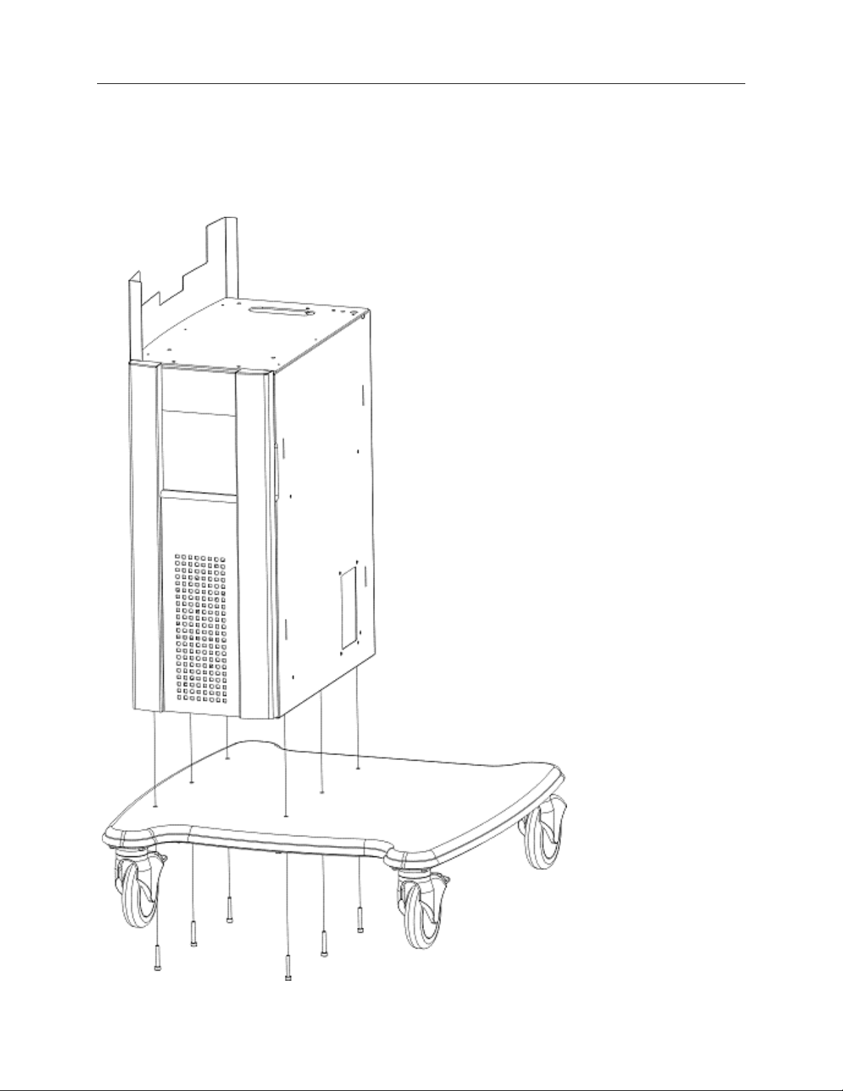
STEP 1 Base and Main Column Assembly..................................................................6
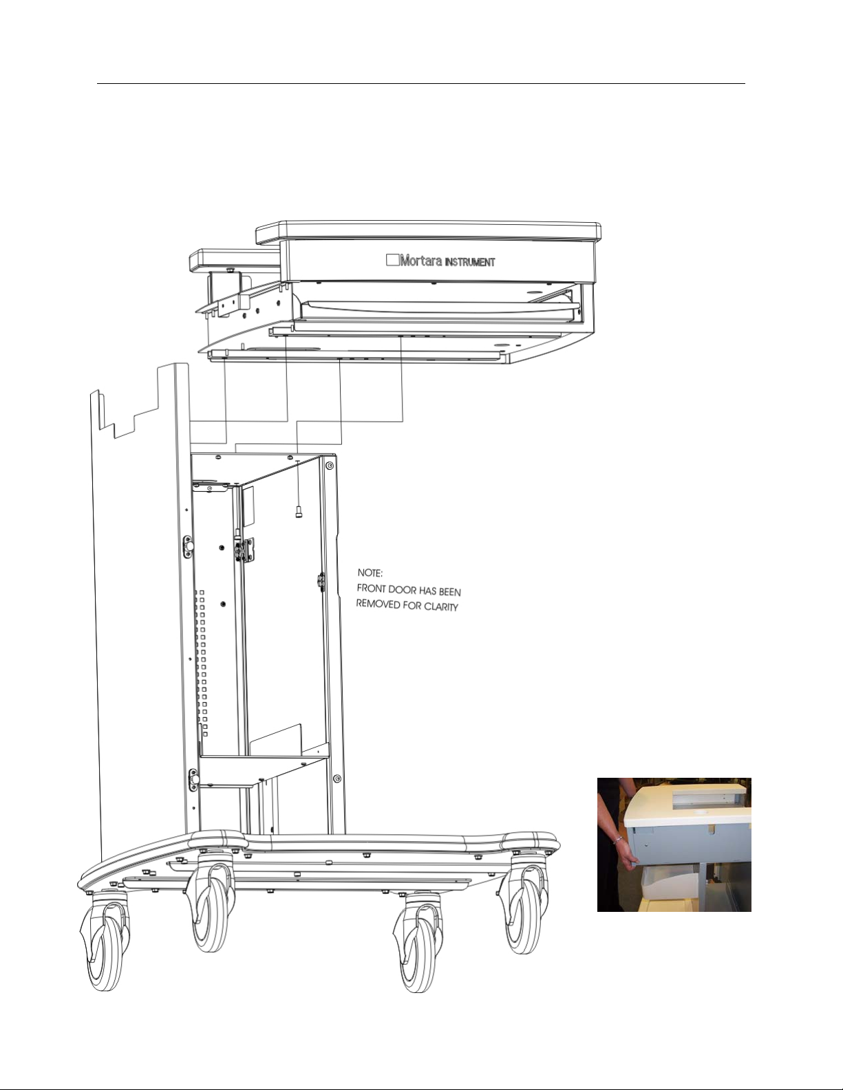
STEP 2 Top Shelf Assembly .......................................................................................7
STEP 3 Route the Monitor Cables and Remove Back Cover......................................8
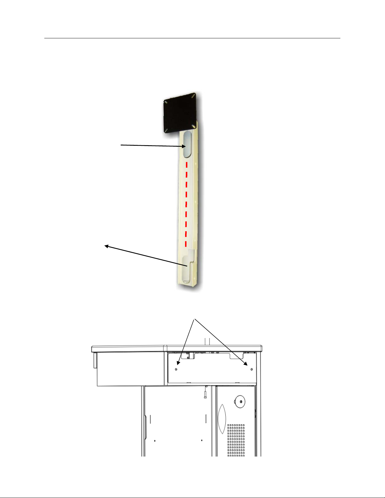
STEP 4 Monitor Mount Assembly................................................................................9
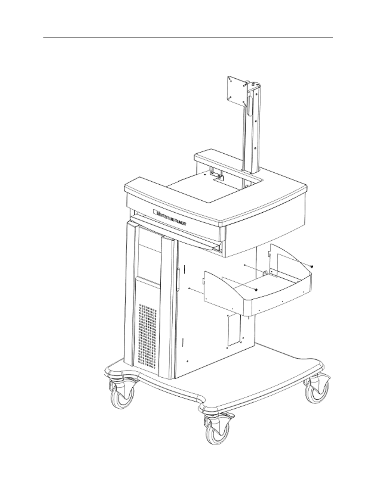
STEP 5 Installation of Storage Bin.............................................................................10
SECTION 2 -- INSTALLATION OF COMPUTER COMPONENTS
...........................................................................................11
STEP 1 Installing Isolation Transformer ....................................................................11
STEP 2 Installing the Computer ................................................................................12
Remote Keypad.........................................................................................................14
Optional Network (LAN) Connection..........................................................................14
STEP 3 Routing the cables........................................................................................15
STEP 4 Installing a Laser Printer...............................................................................16
STEP 5 Installing a Thermal Writer............................................................................17
STEP 6 Installing the LCD Display ............................................................................18
STEP 7 Connect and Route the Display Cables to the Computer.............................18
STEP 8 The M12-USB Patient Module......................................................................19
STEP 9 Installing the Rear Cover..............................................................................19
COMPLETED X-SCRIBE SYSTEM........................................20
M12C-USB, M12RF2500-USB, and M12RF608-USB Installation
...........................................................................................21
COMPONENTS.........................................................................................................21
Tango NIBP Mounting Bracket (optional) ..................................................................22

MORTARA INSTRUMENT SPECIFICATION
MIS-11-151-01 Rev. 9
© 2007-10 Mortara Instrument, Inc. CONFIDENTIAL PAGE 3 OF 22
COMPONENTS
Material Supplied with Cart Assembly (Fully knocked-down version shown. Almost all
parts come assembled in a variant which only needs the monitor mount installed)
Tools included for Assembly:
1 - Phillips screwdriver #2
1 –Allen Wrench
Parts Kit included for Assembly
Top Shelf
Assembly
M6 X 40 mm Screws M6 X 12 mm
Screws
M6 X 25 mm Screws
M4 x 10 mm
Screws
Tools and Screws are
packaged in the box
with Storage Bin
Assembly.
M4 x 12 mm
Screws
Power Cord
Strain Relief
Cable Protecting
Grommets

MORTARA INSTRUMENT SPECIFICATION
MIS-11-151-01 Rev. 9
© 2007-10 Mortara Instrument, Inc. CONFIDENTIAL PAGE 4 OF 22
Main Column
Assembly
Base Assembly with Locking Front Wheels
Included when a Thermal Writer is part of the system configuration:
Storage Bin Assembly
Note: a second storage
bin is optional
Wire basket for Thermal paper
Wire basket mount and two
M4 X 10 mm screws

MORTARA INSTRUMENT SPECIFICATION
MIS-11-151-01 Rev. 9
© 2007-10 Mortara Instrument, Inc. CONFIDENTIAL PAGE 5 OF 22
Monitor Mount
Assembly
LASER SHELF KIT - OPTIONAL
Laser Printer Support Bin Assembly
Desk Top Shelf Assembly
(when thermal writer is not present)
Four M4 X 10 mm Screws

MORTARA INSTRUMENT SPECIFICATION
MIS-11-151-01 Rev. 9
© 2007-10 Mortara Instrument, Inc. CONFIDENTIAL PAGE 6 OF 22
SECTION 1 -- ASSEMBLY OF CART (For “Assembled” cart,
skip to Step 3)
STEP 1 Base and Main Column Assembly
oPLACE BASE ASSEMBLY ON
FLOOR
oLIFT MAIN COLUMN
ASSEMBLY ONTO BASE.
TAKE CARE NOT TO
SCRATCH THE BASE
ASSEMBLY. THIS IS A TWO
PERSON JOB.
oUSING SIX M6 X 40 mm
SCREWS, FASTEN THE MAIN
COLUMN ASSEMBLY TO THE
BASE ASSEMBLY. USE THE
SUPPLIED ALLEN WRENCH
TO TIGHTEN.
oMAKE SURE ALL SIX
FASTENERS ARE TIGHTENED
BEFORE MOVING ON TO THE
NEXT STEP.

MORTARA INSTRUMENT SPECIFICATION
MIS-11-151-01 Rev. 9
© 2007-10 Mortara Instrument, Inc. CONFIDENTIAL PAGE 7 OF 22
STEP 2 Top Shelf Assembly
IMPORTANT! TWO PEOPLE RECOMMENDED FOR THIS STEP
oAN ASSISTANT
SHOULD HOLD
ASSEMBLY IN PLACE
TO PREVENT IT FROM
FALLING.
oFASTEN TOP SHELF
ASSEMBLY WITH FOUR
M6 X 12 mm SCREWS,
USING THE SUPPLIED
ALLEN WRENCH.
oMAKE SURE ALL FOUR
SCREWS ARE
SECURELY FASTENED.

MORTARA INSTRUMENT SPECIFICATION
MIS-11-151-01 Rev. 9
© 2007-10 Mortara Instrument, Inc. CONFIDENTIAL PAGE 8 OF 22
STEP 3 Route the Monitor Cables and Remove Back Cover
ROUTE THE MONITOR CABLES THROUGH THE MONITOR MOUNT ASSEMBLY
PRIOR TO INSTALLATION.
Monitor
Cables in
out
through
LOOSEN THE CAPTIVE SCREWS IN THE DESK TOP REAR COVER
AND REMOVE THE REAR COVER.
REMOVE
COVER

MORTARA INSTRUMENT SPECIFICATION
MIS-11-151-01 Rev. 9
© 2007-10 Mortara Instrument, Inc. CONFIDENTIAL PAGE 9 OF 22
STEP 4 Monitor Mount Assembly
oSLIDE MONITOR MOUNT
INTO HOLE IN THE TOP OF
THE TOP SHELF
ASSEMBLY. TAKE CARE
NOT TO SCRATCH THE
TOP.
oFASTEN THE MONITOR
MOUNT ASSEMBLY TO
THE CART WITH TWO M6
X 25 mm SCREWS USING
THE SUPPLIED ALLEN
WRENCH.
oMAKE SURE THAT
SCREWS ARE SECURELY
TIGHTENED.
NOTE THE
SECONDARY
VIEW THAT
SHOWS WHERE
SECOND SCREW
IS ASSEMBLED.
IF SCREW IS
DROPPED
INSIDE OF
COLUMN, GO TO
BOTTOM OF
COLUMN AND
REACH INTO THE
PRINTER CABLE
ACCESS PANEL
FROM INSIDE OF
CART TO
RETRIEVE.

MORTARA INSTRUMENT SPECIFICATION
MIS-11-151-01 Rev. 9
© 2007-10 Mortara Instrument, Inc. CONFIDENTIAL PAGE 10 OF 22
STEP 5 Installation of Storage Bin
oASSEMBLE
STORAGE BIN
ASSEMBLY BY
SLIDING TABS ON
UNIT INTO SLOTS
ON THE SIDE OF
THE CART.
oUSE THE
SCREWDRIVER TO
TIGHTEN TWO M4 X
10 mm SCREWS TO
THE SIDE OF CART
TO SECURELY
FASTEN THE
SHELF ASSEMBLY
TO CART.

MORTARA INSTRUMENT SPECIFICATION
MIS-11-151-01 Rev. 9
© 2007-10 Mortara Instrument, Inc. CONFIDENTIAL PAGE 11 OF 22
SECTION 2 -- INSTALLATION OF COMPUTER
COMPONENTS
STEP 1 Installing Isolation Transformer
Note: Style may vary depending on options.
Ensure that the input and output
voltage settings on the Isolation
Transformer are appropriate for the
country.
Ensure the power switch is in the “on”
position.
Insert the Isolation Transformer with
the power entry module facing the
back. Carefully slide the Isolation
Transformer into the bottom opening
on the front of the cart being careful
not to scratch the cart.
Connect the Power Entry Cord to
the Isolation Transformer then
place the plastic cord protector on
the cable and insert it into the back
power cord cutout.
Connect shrouded power cables to
the isolation transformer.
NOTE: Only Mortara Instrument, Inc.
equipment and equipment authorized
by Mortara Instrument, Inc. should be
connected to the Isolation Transformer.

MORTARA INSTRUMENT SPECIFICATION
MIS-11-151-01 Rev. 9
© 2007-10 Mortara Instrument, Inc. CONFIDENTIAL PAGE 12 OF 22
STEP 2 Installing the Computer
Measure the dimensions of the side and back brackets to ensure that they will
accommodate the computer dimensions. Using the provided screwdriver, adjust if
necessary before inserting the computer. Slide the computer into the front opening in
the cart to the back support bracket.
Mounting M12-USB and LAN Isolator Adapter
Place M12-USB device on top shelf
Plug USB cable into USB slot back of CPU
Place LAN Isolator device on top of
CPU
Antenna ECG
USB TTL Analog
M12B-USBDevice

MORTARA INSTRUMENT SPECIFICATION
MIS-11-151-01 Rev. 9
© 2007-10 Mortara Instrument, Inc. CONFIDENTIAL PAGE 13 OF 22
When a Mortara Instrument M12-USB module and corresponding M12 Patient Cable
are used, the cable of the M12 needs to be secured by wrapping it into the strain relief
on the M12-USB box. Then place the USB device on the shelf to the left of the monitor
post. This will prevent stress on the cable connector to the M12-USB patient module
should the cable be pulled upon during routine use.
Place 18” antenna cable BNC connectors
onto M12 Multi-Modality Module
Feed cables through cut out slots on back of
cart
Place antenna adhesive clips at opposing
ends of back of cart approximately 18” apart
On-board RJ45 connector. LAN
connection from network isolator.
M12USB interface connector to any USB
port on the CPU
An optional Laser Printer USB cable will
be installed in any open USB port.
The USB Dongle will be installed into any
open USB port. This Dongle is required
for the operation of your X-Scribe Stress
System.

MORTARA INSTRUMENT SPECIFICATION
MIS-11-151-01 Rev. 9
© 2007-10 Mortara Instrument, Inc. CONFIDENTIAL PAGE 14 OF 22
Optional Computer Connections
Remote Keypad
Optional Network (LAN) Connection
Isolator
RS 232 Cable for Treadmill
Network Cable to Isolator
Z200+ Printer connection
Note: The LAN isolator box is connected
between the computer’s on-board network
connection and the customer’s network
connection.
Plug in the USB cable
coming from the Remote
Keypad to any open USB
port on the back of the CPU.

MORTARA INSTRUMENT SPECIFICATION
MIS-11-151-01 Rev. 9
© 2007-10 Mortara Instrument, Inc. CONFIDENTIAL PAGE 15 OF 22
STEP 3 Routing the cables
Wrap the cables neatly behind the computer and route through the cutouts.
Connect “Cross-over” design Ethernet patch
cable from Z200+ thermal printer to secondary
LAN card only, as shown. “Cross-over” cable
must be used for this connection.
Lower enlarged view of cutout for
monitor, Mouse and Keyboard cables.
Keyboard tray cutout for
Mouse and Keyboard cables.

MORTARA INSTRUMENT SPECIFICATION
MIS-11-151-01 Rev. 9
© 2007-10 Mortara Instrument, Inc. CONFIDENTIAL PAGE 16 OF 22
STEP 4 Installing a Laser Printer
If a Laser printer is to be installed with the system, install the laser printer support bin.
Use the screwdriver to secure the two M4 x 10 mm screws and place the laser printer
on the bin.
Slide the Desk Top Shelf into the Cart Desk Top as shown below.
Secure with two M4 x 10 mm screws, supplied with the Laser Shelf Kit,
using the supplied screwdriver.
Route the laser printer cables through the cutout on the side of the cart tower.

MORTARA INSTRUMENT SPECIFICATION
MIS-11-151-01 Rev. 9
© 2007-10 Mortara Instrument, Inc. CONFIDENTIAL PAGE 17 OF 22
STEP 5 Installing a Thermal Writer
If a thermal writer is to be installed with the system, slide the Z200+ into the space in the
cart desk top as shown below.
Feed the power cable and the network cable for the Z200+ thermal printer through the
cutout and insert them as shown below.
Secure the wire basket mounting support
plate with supplied M4 x 10 mm screws
and attach the basket.

MORTARA INSTRUMENT SPECIFICATION
MIS-11-151-01 Rev. 9
© 2007-10 Mortara Instrument, Inc. CONFIDENTIAL PAGE 18 OF 22
STEP 6 Installing the LCD Display
Use the four M4 x 12 mm screws included in the parts kit to secure the monitor to
the mounting plate of the Monitor Mount assembly.
STEP 7 Connect and Route the Display Cables to the
Computer
Connect the monitor cable, USB power cable and
power cable to the monitor and route the other
ends that have been fed through the Monitor Mount
Assembly through the cutout leading to the
computer back.
Connect cables to the
mounted monitor.

MORTARA INSTRUMENT SPECIFICATION
MIS-11-151-01 Rev. 9
© 2007-10 Mortara Instrument, Inc. CONFIDENTIAL PAGE 19 OF 22
STEP 8 The M12-USB Patient Module
Connect the cables of the USB
STEP 9 Installing the Rear Cover
Finally, install the Rear Cover by placing the two slots over the tabs located on the
top of the back panel of the Desk Top Assembly.
Secure the captive Rear Cover screws using the supplied screwdriver.

MORTARA INSTRUMENT SPECIFICATION
MIS-11-151-01 Rev. 9
© 2007-10 Mortara Instrument, Inc. CONFIDENTIAL PAGE 20 OF 22
COMPLETED X-SCRIBE SYSTEM
Finished Cart with the Thermal
Writer configuration and
Computer components installed.
Finished Cart with the Laser
Printer configuration and no
Computer components.
Table of contents
Other Mortara Instrument Medical Equipment manuals

Mortara Instrument
Mortara Instrument ELI 25O User manual

Mortara Instrument
Mortara Instrument Quinton Q-Stress 4.0 Installation manual

Mortara Instrument
Mortara Instrument ELI 100 User manual

Mortara Instrument
Mortara Instrument ELI 100 User manual

Mortara Instrument
Mortara Instrument Ambulatory X-12 User manual
Popular Medical Equipment manuals by other brands

B. Braun
B. Braun Aesculap GA553 Instructions for use/Technical description

Contec Medical Systems Co.
Contec Medical Systems Co. GIMA ECG300G user manual

I-Tech
I-Tech Mio-Sonic user manual

Hillrom
Hillrom A-71400 Instructions for use

DRTECH
DRTECH EXT 1824G Safety and Regulatory Information with User Manual

Smith & Nephew
Smith & Nephew RENASYS GO quick start guide