SenseAir aSENSE User manual

Dokument
IMA 242
HFE501
Rev
3 Sid
1 (16)
CO2/temperaturgivare
Allmänt
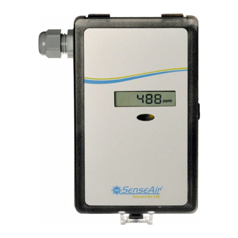
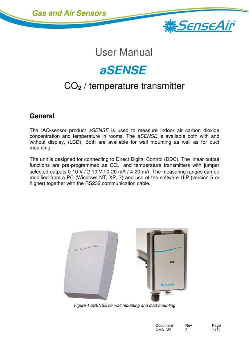
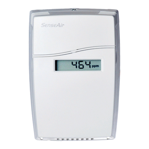
Luftanalysatorn A-SENSE är konstruerad för att mäta koldioxid och temperatur.
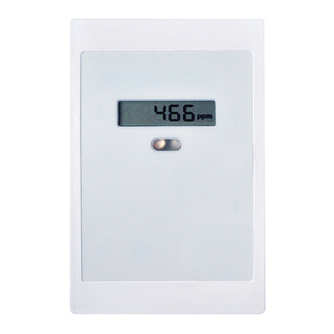
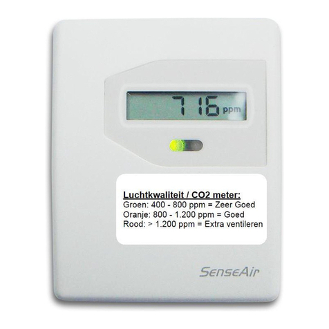
Modell A-SENSE-D har display. Båda är tillgängliga för såväl väggmontering som för
kanalmontering.
Enheten är avsedd att uppkopplas mot datorundercentraler (DUC: ar). De linjära
utgångarna är förprogrammerade som koldioxid- resp. temperaturtransmitter med
bygelbara val 0-10 V / 2-10 V /0-20 mA / 4-20 mA. Omvandlingsområden kan ändras
via en dator (Windows) och programmet UIP (version 5.0 eller högre) och RS232
A232 kommunikationskabeln.
A-SENSE för montering på vägg och UG-A-SENSE för montering i ventilationskanaler
A-SENSE, A-SENSE-D
Installationsmanual
SV – Sida 1
EN – Page 9

Dokument
IMA 242
HFE501
Rev
3 Sid
2 (16)
Monteringsanvisning
Montering av A-SENSE för vägg, se nedan.
Montering av UG-A-SENSE för ventilationskanal, vänligen se separat
monteringsanvisning.
För elektrisk installation, se sidan 4.
Isärtagning av mätaren
Drag överdelen rakt uppåt
Skjut fronten uppåt Vik fronten snett utåt och
och håll emot bakstycket tag loss den från hakarna (nr 1)
3
2
5
14
1
1 överdel
2 front
bestående av
mellanplatta
med faststiftat
lock
3 bakstycke
4 skruv
5 etikett med
inställningar
på insidan av
överdelen

Dokument
IMA 242
HFE501
Rev
3 Sid
3 (16)
Uppsättning av mätaren
Bakstycket skruvas fast i väggen A Stick in hakarna i hålen i övre delen av
bakstycket
Skruvskallens diameter skall vara max 7,5 mm B Tryck in fronten mot bakstycket så att den låses
Skruvskallens höjd skall vara max 2,5 mm av hakarna i frontens nederkant.
Överdelen skjuts in under bakstyckets
låshakar och låses med skruv
Kretskortet måste hanteras försiktigt och skyddas mot elektrostatiska
urladdningar om det tas loss från kapslingen. Kretskortet behöver
vanligtvis inte tas loss.
A
B
Väggmontage
Montera mätaren på vägg där den inte
utsätts för direkt solljus eller drag.
Vid montering över apparatdosa eller
installationsrör ska dessa tätas, för att
undvika drag som kan påverka
mätarens funktion och noggrannhet.

Dokument
IMA 242
HFE501
Rev
3 Sid
4 (16)
Elektriska anslutningar
Strömförsörjning skall anslutas till och (fas/pluspol resp. nolla/minuspol).
Om den analoga utgången skall anslutas måste samma jordreferens användas till
både A-SENSE och till signalmottagaren! Om inte olika transformatorer användes
för dessa gäller att:
VID AC- OCH DC-MATNING MÅSTE
NOLLAN VARA JORDREFERENS I HELA
SYSTEMET!!!
OBS!
Samma jordreferens måste användas
till både A-SENSE och till
signalmottagaren!
Anslut matningsspänningen direkt efter
uppsättningen. Analogutgången behöver
inte anslutas förrän den skall användas.
Plint
Funktion
Elektriska data
Anmärkning
Spänningsmatning (+)
Systemjord (-)
24 VAC/DC+ (+-20%), 1W
24 VAC/DC-
Se not 1!
Out(1)
Out(2)
Analog utgång 1 (+)
Analog utgång 2 (+)
0-10 VDC eller 0-20 mA,
2-10 VDC eller 4-20 mA,
Samma som utgång 1
0…2000 ppm CO2
0…50 oC
Enligt byglarna för Out(1)
resp Out(2) och Startpunkt.
Se not 2!
Tabell I. Plintanslutningar för A-SENSE
Not 1:Jordterminalen är negativ pol i DC kraftsystem och nollan i AC system
(halvvågslikriktning). En enda transformator kan användas för hela systemet.
Not 2: A-SENSE
kan leverera spännings- eller strömutgång för Out(1) / Out(2) (väljes oberoende av
varandra med byglar). Både ström- och spänningsutgång kan ha startpunkt vid 0% (0-10V eller 0-
20mA) eller 20% (2-10V eller 4-20mA). Samma startpunkt används för båda utgångarna. Se
funktionsmanualen.
~
+
~
+

Dokument
IMA 242
HFE501
Rev
3 Sid
5 (16)
+
~
Kretskort till A-SENSE
Plintanslutningar och byglar för väggmonterad mätare ses till höger. Mörkare
positioner är grundinställningar. Plintarna och byglarna är placerade under överdelen
Anslutning av UG-A-SENSE via skruvplinten vid kanalmontering.

Dokument
IMA 242
HFE501
Rev
3 Sid
6 (16)
Konfigurering av utgångar
Mätarna levereras från fabriken (om inte annat har beställts) med 0 - 10VDC linjära
utgångar för Out(1) & Out(2) (se tabell II). Om andra lösningar behövs för
applikationen så skall byglarna konfigureras innan spänningen ansluts. Byglarna kan
väljas oberoende av varandra utom för valet av startpunkt som påverkar båda de
linjära utgångarna Out(1) och Out(2). Alternativa mätområden för utgångarna väljs
genom PC - mjukvara.
Bygel
Läge
Funktion
Bygel för
val av
startpunkt
0 %
20%
Bygeln i toppläge ger 0Vdc eller 0mA som startpunkt för Out(1), Out(2)
(0-20mA eller 0-10V).
Bygeln i bottenläge ger 2Vdc eller 4mA startpunkt för Out(1), Out(2) (4-20mA
eller 2-10V
Out(1)
Ström
Spänning
Ansluts bygeln i läge Ström så får Out(1) mätområdet 0/4-20mA.
Ansluts bygeln i läge Spänning så får Out(1) mätområdet 0/2-10VDC.
Out(2)
Ström
Spänning
Ansluts bygeln i läge Ström så får Out(2) mätområdet 0/4-20mA.
Ansluts bygeln i läge Spänning så får Out(2) mätområdet 0/2-10VDC.
Tabell II. Konfigureringsbyglar för A-SENSE
Självdiagnostik
Systemet innehåller en fullständig självdiagnostik som utförs automatiskt varje gång
spänningen slås på. För
A-SENSE kontrolleras interna spänningsregulatorer och
utgångar. Dessutom kontrolleras hela tiden att sensorn fungerar genom att mätvärdet
kontrolleras mot godkänt mätområde. Funktionskontrollen returnerar en felkod till
systemets RAM-minne. Felkoderna blir tillgängliga genom att ansluta en PC med
speciell RS232-kabel till UART glidkontakten. Felkoderna visas i dataprogrammet
UIP version 5.0 eller högre. Uppvärmning och Utanför mätområdet återställs
automatiskt när mätaren återgår till normal funktion. Alla andra felkoder måste
återställas manuellt efter återgång till normal funktion. Detta sker genom att
matningsspänningen kopplas från / till.

Dokument
IMA 242
HFE501
Rev
3 Sid
7 (16)
Felkoder och föreslagna åtgärder
Bit # Felkod Felbeskrivning Föreslagna åtgärder
0 N/A
Allvarligt fel
Försök att starta om mätaren genom att
koppla från/ till matningsspänningen.
Kontakta återförsäljaren
1 2
Reserverad
2 4
Beräkningsfel
Indikerar fel EEPROM- konfigurering. Försök att starta om mätaren genom att
koppla från/ till matningsspänningen.
Kontrollera inställning och konfigurering
med mjukvaran UIP version 5.0 eller högre.
Kontakta återförsäljaren
3 8
Fel på utgången
Upptäckta fel vid signalgenerering och
signalbearbetning.
Kontrollera anslutningar och utgångarnas
laster.
Kontrollera utgångarnas status med
mjukvaran UIP version 5.0 eller högre.
4 16
Fel vid självdiagnostiken
Kan indikera behov av nollkalibrering
eller utbyte av mätare.
Kontrollera självdiagnostikens detaljerade
status med mjukvaran UIP version 5.0 eller
högre.
Kontakta återförsäljaren
5 32
Utanför mätområdet
Inträffar samtidigt med det flesta
andra fel. Kan indikera kortslutning
eller felaktiga mätgivare och ingångar.
Återgår automatiskt när orsaken till
felet försvunnit.
Prova mätaren i frisk luft.
Kontrollera temperaturgivarens anslutning.
Kontrollera självdiagnostikens detaljerade
status med mjukvaran UIP version 5.0 eller
högre.
Se not 1!
6 64
Minnesfel
Kontroll under sparoperation i
internminne har funnit ett fel
Kontrollera självdiagnostikens detaljerade
status med mjukvaran UIP version 5.0 eller
högre.
7 128
Uppvärmning
Sätts alltid vid start och
spänningsbortfall. Återgår efter
uppstartssekvensen.
Om felet inte försvinner inom en halv minut
- kontrollera att drivspänningen är stabil!
Not 1. Någon mätprob är utanför mätområdet. Inträffar t ex vid mycket höga CO2-värden. I detta fall
kvitteras felkoden när mätvärdena återgår till normala. Kan också indikera att en nollkalibrering måste
göras. Om CO2-värdena är normala och felkoden fortfarande är kvar kan temperaturgivaren vara
trasig eller ha dålig kontakt.
Anmärkning: Om flera felkoder upptäcks samtidigt adderas de och blir till en enda felkod!
OBS! Mätnoggrannheten är definierad vid kontinuerlig drift (minst tre veckor efter installation)

Dokument
IMA 242
HFE501
Rev
3 Sid
8 (16)
Underhåll
Mätaren A-SENSE är i grunden underhållsfri. En intern självkalibreringsfunktion
justerar CO
2-
sensorns långtidsdrift. För att säkerställa högsta noggrannhet
rekommenderas kalibrering av mätaren vart femte år (om inga speciella incidenter
har inträffat). En nollkalibrering kan göras med en PC och mjukvaran UIP software
version 5.0 (eller högre). Denna mjukvara och en speciell RS232-kabel ingår i
nollkalibreringsväskan. Kabeln skall anslutas till UART glidkontakt. Om
kontrollparametrar skall ändras eller omkalibrering göras, måste PC användas. Detta
kan göras på plats utan att störa ventilationssystemet.
Denna produkt överensstämmer med
EMC 2004/108/EC, 92/31/EEG och utdrag ur CE-marking Directive 93/68/EEC
Produkten uppfyller kravet:
EN 61326-1:2006, Class B equipment, Table 1 - Basic immunity test
requirements
DISTRIBUTÖR
Calectro AB
Box 4113
426 04 VÄSTRA FRÖLUNDA
Tel vxl: 031-69 53 00
Fax: 031-29 32 91
Hemsida: www.calectro.se
E-post: [email protected]

Dokument
IMA 242
HFE501
Rev
3 Sid
9 (16)
Installation Manual
A-SENSE, A-SENSE-D
CO
2
/ temperature transmitter
General
The IAQ-sensor product A-SENSE is used to measure indoor air carbon dioxide
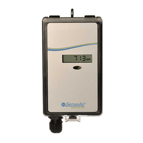
concentration and temperature in rooms. A-SENSE - D is the display model with a
LCD. Both are available for wall mounting as well as for duct mounting.
The unit is designed for connecting to Direct Digital Control (DDC). The linear output
functions are pre-programmed as CO
2
and temperature transmitters with jumper
selected outputs 0-10 V / 2-10 V / 0-20 mA / 4-20 mA. The measuring ranges can be
modified from a PC (Windows) and use of the software UIP (version 5.0 or higher)
together with the communication cable RS232.
Figure 1. A-SENSE for wall mounting and UG-A-SENSE for mounting in ventilation ducts

Dokument
IMA 242
HFE501
Rev
3 Sid
10 (16)
Mounting instruction
Wall mounting of A-SENSE see below.
Duct mounting of UG-A-SENSE, please see separate mounting instruction.
For electrical installation, see page 12.
Dismounting of the sensor
Pull the top part upwards
Push the front part upwards while Fold the front part forwards and
keeping the wall plate steady loose it from the hooks (#1)
3
2
5
14
1
1 top part
2 front part
3 wall plate
4 screw
5 label with
settings
inside the
top part

Dokument
IMA 242
HFE501
Rev
3 Sid
11 (16)
Mounting of the sensor
The wall plate is screwed onto the wall A Put the top tabs of the front part into the top
The screw head diameter should be max 7,5 mm holes of the wall plate.
The screw head height should be max 2,5 mm B Press the lower edge of the case onto
the wall plate to latch
The top part is pushed under the
locking hooks of the wall plate
and is secured with a screw.
If for some reason the PCB must be removed it must be handed carefully
and protected from electrostatic discharge! Normally, removing the PCB is
not required.
A
B
Wall mounting
Mount the sensor on a wall which is
not exposed to direct sunlight or
airflow.
If mounting the sensor on a device
box or conduits, they should be
sealed to avoid airflow which can
affect performance and accuracy of
the sensor.

Dokument
IMA 242
HFE501
Rev
3 Sid
12 (16)
Electrical connections
The power supply has to be connected to and . is considered as
system ground. If the analogue output is connected to a controller the same ground
reference has to be used for the A-SENSE unit and for the control system! Unless
different transformers are used, special precautions need to be taken.
PLEASE NOTE! The A-SENSE signal and power
supply grounds are common
PLEASE NOTE!
The same ground reference has to be used
for the A-SENSE unit and for the control
system!
If possible keep the sensor powered up after
mounting. Connect the analogue output before
measuring.
Connection
Terminal
Function
Electrical Data
Remarks
Power (+)
Power ground (-)
24 VAC/DC+ (+-20%), 1W
24 VAC/DC-
See note 1!
Out(1)
Out(2)
Analogue Output 1 (+)
Analogue Output 2 (+)
0-10 VDC or 0-20 mA,
2-10 VDC or 4-20 mA,
Same as Output 1
0…2000 ppm CO2
0…50 oC
According to positions of
Out(1) or Out(2) and start
point jumpers.
See note 2!
Note 1: The ground terminal is used as negative power supply DC input or AC phase ground
(halfwave rectifier). A single transformer may be used for the entire system.
Note 2:A-SENSE can deliver a voltage or a current loop for Out(1)/ Out(2). To change between
voltage and current output mode the hardware jumpers are used. There is one jumper for Out(1) and
one for Out(2), so that one output can be a voltage output and the other a current output. Both, voltage
output and current outputs, can have start points 0 % (0-10 VDC or 0-20mA) or 20% (2-10 VDC or 4-
20mA). The same start point is used for both outputs.
~
+
~
+

Dokument
IMA 242
HFE501
Rev
3 Sid
13 (16)
+
~
The A-SENSE printed circuit board. The connection terminal area for wall mounted sensors is
enlarged at right. Darker positions are default. The terminals and jumpers are placed under the top
part.
Connection of the UG-A-SENSE via screw terminal at duct mounting.

Dokument
IMA 242
HFE501
Rev
3 Sid
14 (16)
Output Configurations
The sensors/controllers are supplied from the factory (unless otherwise ordered) with
0...10VDC linear outputs for Out(1) and Out(2) (see Table I). If other options are
needed for the application, the output jumpers have to be configured before the unit
is powered up. Each jumper selection is independent from the others, except for the
“Start point selection” jumper, which affects both, Out(1) & Out(2), linear outputs.
Alternative measuring ranges of the outputs can be selected with the software UIP
(version 5.0 or later).
Jumper
Position
Function
Start point
selection
jumper
0%
20%
Jumper top position provides 0Vdc or 0mA start point for Out(1), Out(2)
(0-20mA or 0-10V).
Jumper bottom position provides 2Vdc or 4mA start point for Out(1), Out(2)
(4-20mA or 2-10V).
Out(1)
Current
Voltage
Connection in position Current provides 0/4-20mA output range for Out(1).
Connection in position Voltage provides 0/2-10VDC output range for Out(1).
Out(2)
Current
Voltage
Connection in position Current provides 0/4-20mA output range for Out(2).
Connection in position Voltage provides 0/2-10VDC output range for Out(2).
Table II. Configuration jumpers for A-SENSE
Self-diagnostics
The system contains complete self-diagnostic procedures. A full system test is
executed automatically every time the power is turned on. In addition, constantly
during operation, the sensor probes are checked against failure by checking the valid
dynamic measurement ranges. All EEPROM updates, initiated by the sensor itself,
as well as by external connections, are checked by subsequent memory read back
and data comparisons. These different system checks return error bytes to the
system RAM. The error codes are available by connecting a PC with a special
RS232 cable connected to the UART port slide connector. The error codes are
shown in the software UIP (version 5.0 or later). Warm up and Out of Range are the
only bits that are reset automatically after return to normal state. All other error bits
have to be reset manually after return to normal by power off/on.

Dokument
IMA 242
HFE501
Rev
3 Sid
15 (16)
Error code and action plan
Bit
# Error
code Error description Suggested action
0 N/A
Fatal Error Try to restart sensor by power
OFF/ON. Contact local distributor
1 2
Reserved
2 4 Algorithm Error.
Indicate wrong EEPROM
configuration.
Try to restart sensor by power
OFF/ON.
Check detailed settings and
configuration with UIP software
version 5.0 and higher.
Contact local distributor.
3 8
Output Error
Detected errors during output
signals calculation and
generation.
Check connections and loads of
outputs.
Check detailed status of outputs
with UIP software version 5.0 and
higher.
4 16 Self-Diagnostic Error.
May indicate the need of zero
calibration or sensor
replacement.
Check detailed self-diagnostic status
with UIP software version 5.0 and
higher.
Contact local distributor
5 32
Out of Range Error
Accompanies most of other
errors. Can also indicate
overload or failures of sensors
and inputs.
Resets automatically after
source of error disappearance.
Try sensor in fresh air.
Check connections of temperature
and relative humidity probe.
Check detailed status of
measurements with UIP software
version 5.0 and higher.
See Note 1!
6 64
Memory Error
Non-fatal error during memory
operations.
Check detailed settings and
configuration with UIP software
version 5.0 and higher.
7 128
Warm Up state
Is always set after power up or
power failure. Resets after
restart sequence.
If it doesn’t disappear in half a
minute, check power stability.
Note 1
. Any probe is out of range. Occurs, for instance, during over exposure of CO2sensor, in
which case the error code will automatically reset when the measurement values return to normal.
Could also indicate the need of zero point calibration. If the CO2
readings are normal, and still the
error code remains, the temperature sensor can be defect or the connections to it are broken
.
Remark
:If several errors are detected at the same time the different error code numbers will be
added together into one single error code!
PLEASE NOTE! The sensor accuracy is defined at continuous operation (at
least 3 weeks after installation)

Dokument
IMA 242
HFE501
Rev
3 Sid
16 (16)
Maintenance
The A-SENSE
is basically maintenance free. An internal self-adjusting calibration
function takes care of normal long term drift associated to the CO
2
sensor. To secure
the highest accuracy, a time interval of five years is recommended between CO
2
calibrations, unless some special situations have occurred. A zero calibration can be
performed by use of a PC together with the UIP software version 5.0 (or higher). This
software and a special RS232-cable is included in the service bag Zero Calibration
Service Bag. The cable is to be connected to the UART port slide connector. For
change of control parameters and re-calibration (CO
2
and temperature) this PC tool
has to be used. The check can be done on site without interfering with the ventilation
system.
This product is in accordance with the
EMC 2004/108/EC, 92/31/EEG
including amendments by the CE-marking Directive 93/68/EEC
The product fulfils the following demand:
EN 61326-1:2006, Class B equipment, Table 1 - Basic immunity test requirements
DISTRIBUTOR
Calectro AB
Box 4113
SE-426 04 VÄSTRA FRÖLUNDA, SWEDEN
Telephone: +46-(0)31-69 53 00
Telefax: +46-(0)31-29 32 91
Home page: www.calectro.com
E-mail: [email protected]
Other manuals for aSENSE
7
This manual suits for next models
1
Table of contents
Languages:
Other SenseAir Transmitter manuals

SenseAir
SenseAir tSENSE VAV Disp User manual

SenseAir
SenseAir aSENSE User manual

SenseAir
SenseAir eSENSE II User manual

SenseAir
SenseAir aSENSE User manual

SenseAir
SenseAir aSENSE User manual

SenseAir
SenseAir aSENSE GH (Disp) RL User manual

SenseAir
SenseAir aSENSE User manual

SenseAir
SenseAir eSENSE Ind User manual

SenseAir
SenseAir tSense User manual

SenseAir
SenseAir eSENSE User manual