Moss Motors, Ltd. COBALT 910-890 User manual

Part # 910-890_910-891 -1- Modified 01/17
Shock Tower Brace
Installation Instructions
2016+ Mazda Miata
PART # 910-890
If your MX5 did not come with a shock tower
brace from the factory, a cowl reinforcement
plate, part number 910-891, must be installed
to fit this strut bar. Directions to install the
cowl reinforcement plate can be found at the
end of these instructions.
Parts may vary slightly from figures.
Tools required:
• Ratchet
• Torque wrench
• Sockets: 10mm, 10mm deep,14mm
• Universal joint
• 10" Extension
• 10mm wrench
• Needle nose pliers
• Slip joint pliers
• Rags
Removal of the Factory Shock Brace
1) Disconnect the battery.
2) Remove the front section of the sound tube attached
to the intake at the front of the engine bay. Remove
the two outside hose clamps, and the 10mm bolt
securing the center of the tube. Figure 2.
Figure 2
3) Move the sound tube chamber out of the way by
removing the 10mm bolt securing it to the outside
edge of the engine compartment, and then lifting
straight up to separate it from the shock tower plate.
Figure 3.
Figure 3
4) Remove the factory shock brace. Unfasten the six
nuts securing the brace to the shock tower plates
and firewall. Pull out the rear section of the brace
before the two side sections. Figure 4.

Part # 910-890_910-891 -2- Modified 01/17
Installation Instructions
Figure 4
5) Move the EVP control unit fastened to the passenger
side shock tower plate. Use needle nose pliers to
release the backs of the clips holding the wiring from
the control unit. Unfasten the two 10mm bolts holding
the control unit bracket to the shock tower, and move
it out of the way. The large connector on top of the
control unit does not need to be disconnected.
Figure 5.
Figure 5
6) Remove the passenger side shock tower plate by
unfastening the three 14mm nuts, and lifting it off of
the studs. Figure 6.
Figure 6
7) Move the ecu attached to the driver’s side shock
tower plate. There are three 10mm bolts in total. Two
bolts are located on top connecting the ecu bracket
to the shock tower plate, and the third is located at
the bottom of the ecu. The bottom bolt needs a 10
inch extension and universal joint to unfasten. Gently
move the ecu off the studs of the shock tower plate
and place a rag between the ecu bracket and the
shock tower to protect the paint. Do not disconnect
the ecu from the wiring harness. Figure 7.
Figure 7
8) Remove the driver’s side shock tower plate by
removing the three 14mm nuts.
9) Clean the shock tower surfaces where the new brace
will be mounted. Any debris left over may damage the
paint.
10) Place the new shock tower brace onto the same eight
mounting studs as the factory shock tower brace.
Figure 10.

Part # 910-890_910-891 -3- Modified 01/17
Installation Instructions
Figure 10
11) Using the nuts that were removed earlier, secure the
new brace. Torque the six shock tower nuts to 37-43
ft-lbs, and the two firewall nuts to 12-19 ft-lbs.
12) Bolt the EVP control unit on the passenger side of
the vehicle to the shock brace using the two included
M6x35 bolts, washers, and nuts.
13) Remove the D shaped clip from its line and bushing
located near the EVP control unit. Flip it upside down
and reinstall it to fit the hole in the bracket attached
to the control unit. The rubber bushing underneath
will need to be moved up. When everything is in
place, install the clip into the bracket. Figure 13.
13. Figure 13
14) On the driver’s side of the vehicle, mount the ecu
back in its original location. Use the original bolt
to secure the lower mount of the ecu, and the two
M6x25 bolts, washers, and nuts to secure the top two
mounting holes. Figure 14.
Figure 14
15) Mount the sound tube chamber into place on the
driver’s side. Use the original bolt to secure the
outside mount, and the included M6x40 bolt, 20mm
washer, and nut to install the other side to the shock
brace. Figure 15.
Figure 15
16) Make a connector using the small stainless steel pipe
and rubber hose included in the kit. Push the pipe
into the hose until approximately 3/4” of the pipe
is sticking out, and use one of the included hose
clamps to secure them together. Figure 15.
17) Mount the rubber side of the connector onto the
sound tube chamber, and secure it with the second
clamp from the kit.
18) Using the original bolt, install the long end of the
included bracket where the center of the sound tube
was originally mounted. Figure 18.

Part # 910-890_910-891 -4- Modified 01/17
Moss Europe Ltd.
Hampton Farm Industrial Estate
Hampton Road West, Hanworth Middlesex, TW13 6DB
In the UK: 020-8867-2020 FAX: 020-8867-2030
Moss Motors, Ltd.
440 Rutherford Street, Goleta, California 93117
In the US & Canada Toll Free (800) 667-7872
LOCAL (805) 681-3400 FAX (805) 692-2510
For questions or comments please contact:
Installation Instructions
Designed and Distributed by Moss Motors, Ltd.
Figure 18
19) Rotate the portion of the sound tube that connects
to the intake 180 degrees, so that the bottom is now
facing up. Figure 19.
Figure 19
20) Mount the sound tube to the intake and connector
attached to the sound tube chamber. Use the
included M6x30 bolt, 14 & 20mm washers, and nut to
install it to the bracket. Figure 19.
21) Reconnect the battery.
910-890 BOM
Description Quantity
ASound tube hose 1
BSound tube pipe 1
CSound tube bracket 1
DSound tube clamps 2
EM6 x 25mm 2
FM6 x 30mm 1
GM6 x 35mm 2
HM6 x 40mm 1
I20mm washer 2
J14mm washer 10
K Lock-nut 6
LShock tower bar (not pictured) 1
A
D
E F G H
I
J
K
B
C

Part # 910-891 -5- Modified 01/17
Cowl Reinforcement Plate
Installation Instructions
2016+ Mazda Miata
PART # 910-891
440 Rutherford St. Goleta, CA 93117
1-800-667-7872 • FAX 805-692-2525 • www.MossMotors.com
Parts may vary slightly from figures.
The keen eye will notice the car used for
instructions below had a factory shock tower
brace. Your cars cowl plate will look slightly
different, but the removal process is the
same.
Tools required:
• Ratchet
• 8mm, 10mm, and 14mm Sockets
• Small Needle nose pliers
• Small flat nose screwdriver
• Pick
• Felt tipped pen
This is a factory Mazda part.
1) Disconnect the battery.
2) Remove the covers located at the bottom of each
windshield wiper arm. Lift up on the bottom of
the covers and pull down towards the wiper cowl.
If the cover cannot be removed by hand, a small
screwdriver can be used to gently pry up the bottom.
Figure 2.
Figure 2
3) Unfasten the 14mm nut securing each wiper arm.
Before removing the windshield wipers, use a felt
tipped pen to mark the position where each wiper
arm sits on the motor.
4) Remove both wiper arms and set them aside in a safe
location. Take note of which wiper arm goes on which
side.
5) Remove the entire length of weather stripping
attached to the front cowl. The clips can be released
by hand or by using a set of small needle nose pliers
to compress the releases. Figure 5.
Figure 5

Installation Instructions
Part # 910-891 -6- Modified 01/17
6) Remove the two 10mm nuts securing the hard line
bolted across the firewall. Pull the line and brackets
off of the mounting studs so that it can move freely.
Figure 6.
Figure 6
7) Locate the two covers found at the rear edges of the
wiper cowl. Use a small screwdriver or pick to lift up
the covers by prying up and toward the inside of the
cover. Be gentle to avoid damage to the soft plastic
of the cowl and screw covers. Figure 7.
Figure 7
8) Use an 8mm socket and ratchet to remove the
screws found under each cover. Figure 8.
Figure 8

Moss Europe Ltd.
Hampton Farm Industrial Estate
Hampton Road West, Hanworth Middlesex, TW13 6DB
In the UK: 020-8867-2020 FAX: 020-8867-2030
Moss Motors, Ltd.
440 Rutherford Street, Goleta, California 93117
In the US & Canada Toll Free (800) 667-7872
LOCAL (805) 681-3400 FAX (805) 692-2510
Although every effort has been made to ensure the accuracy and clarity of this information, any suggestions
that you may have that will improve the information (especially detailed installation notes and photos) are
welcome. These instructions were developed and written by Moss Technical Support. If you have any questions
or difficulties with your installation of this product, telephone 800-667-7872 between 7:00 a.m. and 4:00 p.m.,
Pacific Time for assistance.
Installation Instructions
Part # 910-891 -7- Modified 01/17
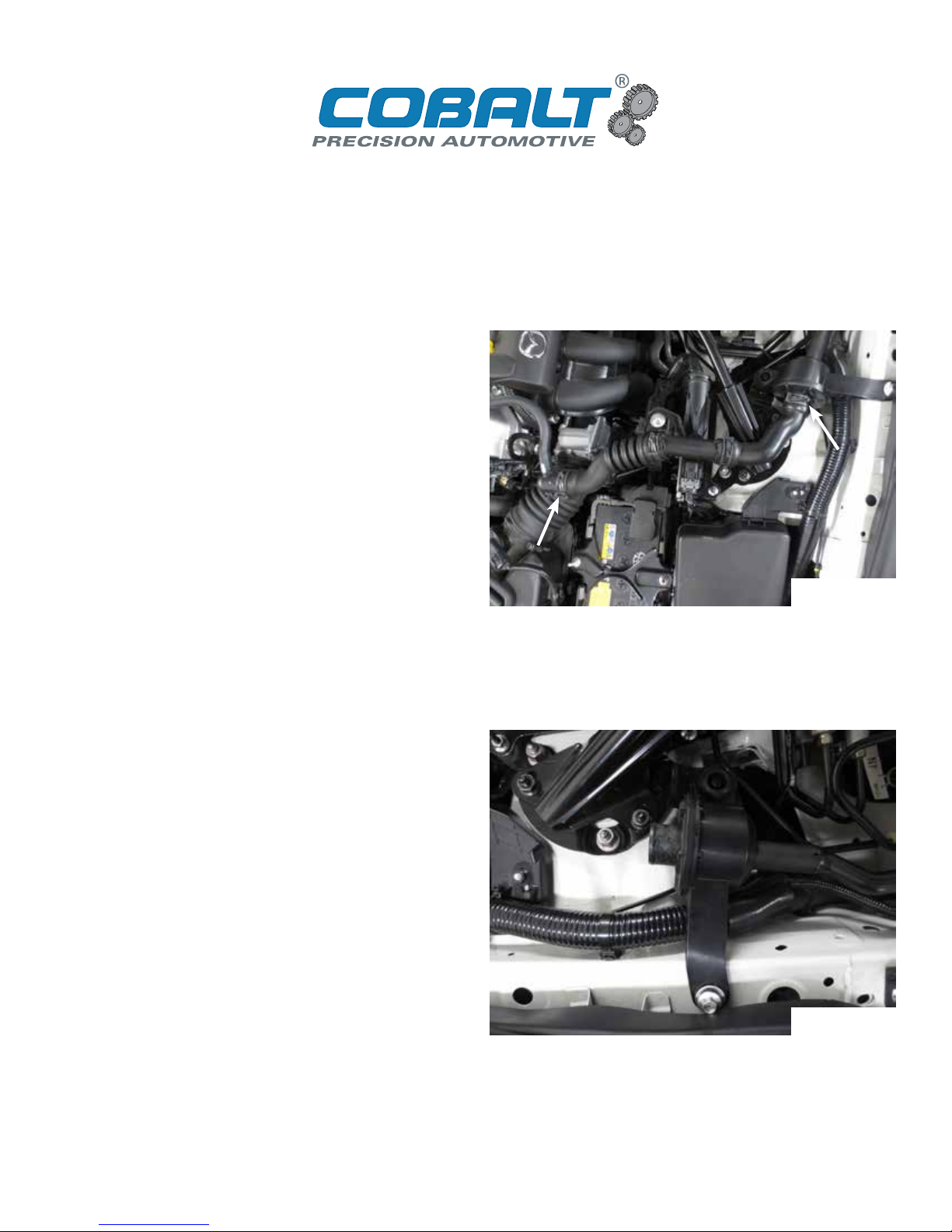
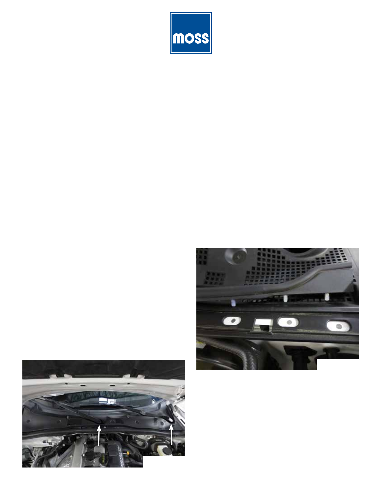
9) Disconnect the windshield washer hose at the two
joints on top of the cowl. Figure 9.
Figure 9
10) Pull the bottom of the cowl towards the front of the
vehicle until the clips holding it to the firewall are free.
11) Move the cowl side to side while continuing to pull it
toward the front of the vehicle until it releases.
12) The cowl will now be free from the vehicle. Take hold
of the driver’s side cowl and lift up and to the outside
to separate it from the passenger’s side half.
13) Lift both sides of the cowl from the vehicle and put
them somewhere safe to be reinstalled later.
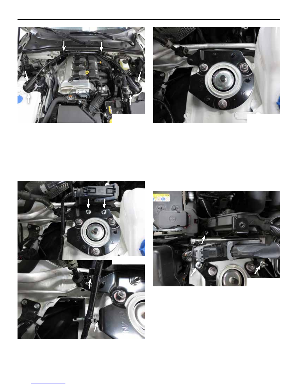
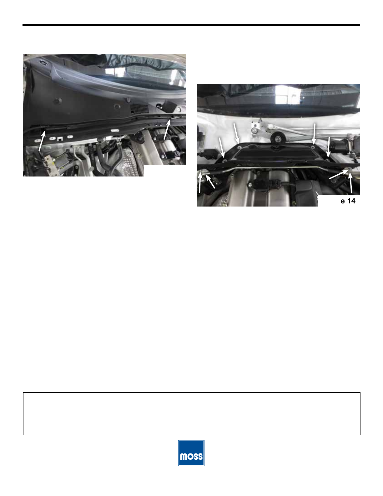
14) The cowl plate will now be visible. Remove the eight
10mm bolts securing it to the vehicle. Four of the
bolts will be on the very front of the firewall next to
the studs for the hard line removed earlier, and the
other four are located on top of the cowl plate.
Figure 14.
Figure 14
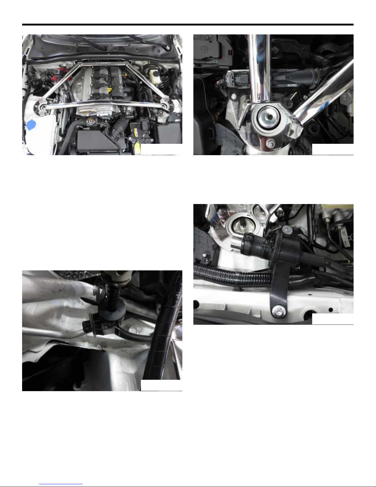
15) Lift the original cowl plate out of the vehicle. The hard
line can be pulled forward gently if it is in the way.
16) Install the new cowl reinforcement plate using the
same eight bolts that held the firewall plate in place.
17) Installation of all removed parts is the reverse of
removal.
18) Use the two included M8x1.25 flange nuts to secure
the rear of the strut brace.
Table of contents
Other Moss Motors, Ltd. Other manuals
Popular Other manuals by other brands

Cleanfix
Cleanfix Homecleaner operating instructions

Tecma
Tecma X-light Operation and installation manual

Ahlborn
Ahlborn ALMEMO 500 Supplementary instructions manual

Martin Audio
Martin Audio W8LM manual

Aqua Medic
Aqua Medic Ocean Light T5 Operation manual

GIGA-TMS
GIGA-TMS TS100 series Hardware user's guide

MICROMATIC
MICROMATIC MDD23W Series Installation, use & maintenance guide

AquaticLife
AquaticLife MACRO AQUA FLOW SWING Instruction guide

Delta OHM
Delta OHM HD35AP series operating manual

Purpleline
Purpleline kojack KJ4T user manual

Team C
Team C TS4-TE user manual

Silvercrest
Silvercrest 289362 Operation and safety notes