I08-0592 0620141 of 2
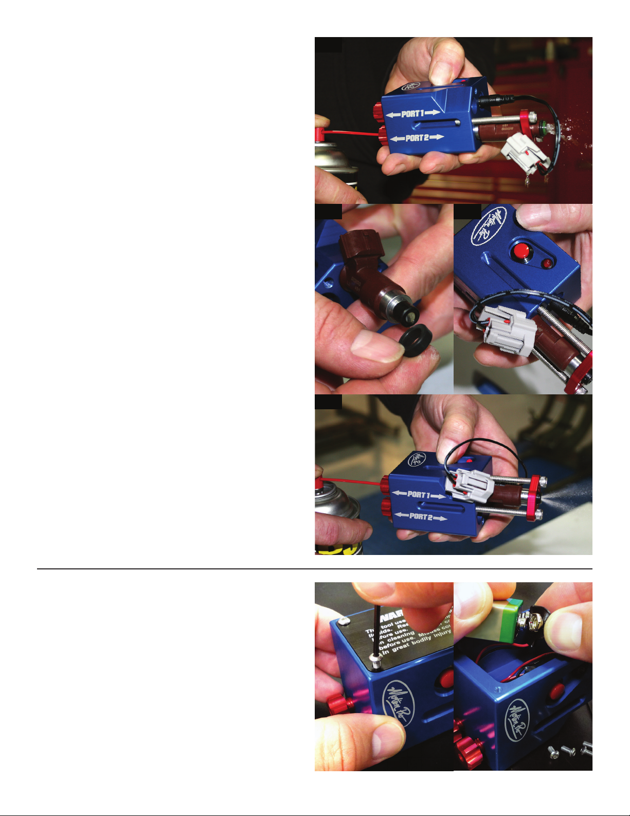
Press the red button to activate the fuel injector and ush
(Fig 5). Note that you will NOT see any spray pattern. This
step is to back ush the injector and remove any dirt or
debris that may accumulate in the injector. Remove the
injector and proceed to Step 2.
CLEANING FUEL INJECTOR
STEP 2:
Remove the lower compression seal on the injector so that
it does not get damaged by the clamp and install the fuel
side of the injector into the tool (Fig 6). For this operation
theinjector will be inserted into Port 1, however some style
injectors may need to be placed into Port 2.
Install the clamp and the electrical connector as shown in
the Fig 7, being careful not to damage the O-rings. Again,
DO NOT OVER TIGHTEN THE SCREWS.
Loosen red knob on the port opposite fuel injector and
insert the tube from the aerosol can into the bottom of the
tool as shown in Fig 8. Tighten the red knob to seal the
tube to the injector cleaner as before.
Press the red button to activate the injector and clean as
shown in (Fig 8).
WARNING!
Cleaning fuel injectors should be done by a trained
mechanic, following procedures set out in the vehicle’s
factory service manual. Follow instructions in factory
service manual forremoval and installation of fuel injector.
This tool is designed for use with commonly available
fuel injector cleaning uids only. Read warning labels
and directions for use on cleaning uid container before
use. Make sure you have adequate ventilation and do not
inhale cleaning uid or fumes. Always wear safety glasses
when using this tool! Most fuel injector cleaner uid is
highly ammable. Wear appropriate clothing, do not use
near open ame, and do not smoke when using this tool.
Improper use of this tool could damage your fuel injector
and/or could cause great bodily injury or death.
FIG 5
FIG 6 FIG 7
BATTERY REPLACEMENT
To access the battery, you will need a 2 mm hex to
remove the bolts from the side plate. Caution: Carefully
unsnap the battery from the connector, pulling too
hard may cause damage to the connector.
FIG 8


