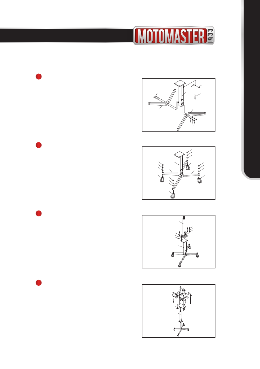
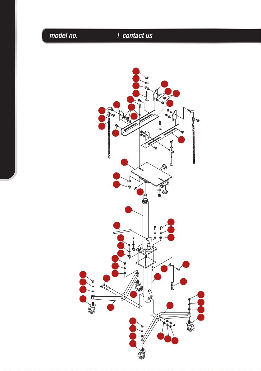
ASSEMBLY INSTRUCTIONS
Put the bracket seat assembly (1) upright,
then align the holes of foot base (2) with the
holes on the column (1), use the screws (3),
at washer (4), lock washer (5) and nuts (6)
to x and tighten it. (Fig. A)
1
2
Put the pump assembly (13) upright on the
bracket seat assembly (1), use the bolts (11),
at washers (4) and nuts (6) to x and tighten
it. (Fig. C)
3
4
Put the caster (7) into the hole as shown on
diagram, use the at washer (8), lock washer
(9) and nut (10) to x and tighten it, ensuring
the caster’s mobility. Repeat for each caster.
(Fig. B)
Fig. A
Fig. B
Fig. C
Fig. D
Put the bracket plate assembly (14) on the piston
rod and x it by using the bolt (18). Then put the
slide (28) on the bracket plate assembly (14) as
shown on diagram, and x it by using the bolt
(19), at washer (4) and nut (6). Then tighten the
safety block (23) on the slide (28) by using the
bolt (19), at washer (4) and nut (6). Screw on
and tighten the circular bolt (22), at washer (4)
and nut (6) to safety block (23). Then put the
chain hook (24) through the chain hook seat (25)
as shown on diagram, and lock it with the at
washer (26) and wing nut (27). Insert the other
end in D shackle (21) and lock it, hang one end
of the chain (20) on the chain hook (24),
3
5
4
6
1
22
15
16
17
7
8
9
10
7
8
9
10
7
8
9
10
17
2
8
9
10
2
1
13
6
4
11
6
4
11
13
18
4
4
4
14
19
19
20
21
22
24
23
23
25
26
27
28
28
6
6
6
7
ASSEMBLY INSTRUCTIONS