Bend-Pak RJ-45 User manual

INSTALLATION AND OPERATION MANUAL
SHIPPING DAMAGE CLAIMS
When this equipment is shipped, title passes to the
purchaser upon receipt from the carrier.
Consequently, claims for the material damaged in
shipment must be made by the purchaser against the
transportation company at the time shipment is received.
BE SAFE
Your new lift was designed and built with safety in
mind. However, your overall safety can be increased by
proper training and thoughtful operation on the part of the
operator. DO NOT operate or repair this
equipment without reading this manual and
the important safety instructions shown inside.
1645 Lemonwood Dr.
Santa Paula, CA. 93060, USA
Toll Free 1-800-253-2363
Tel: 1-805-933-9970
Fax: 1-805-933-9160
www.bendpak.com
Keep this operation manual near the
machine at all times. Make sure that
ALL USERS read this manual.
COMMERCIAL GRADE
ROLLING BRIDGE JACKS
MODELS:
RJ-45; RJ-45S; RJ-6;
RJ-7: RJ-9; RJ-12;
RJ-15; RJ-18; RJ-25.
PLEASE READ THE ENTIRE CONTENTS OF THIS MANUAL PRIOR TO
INSTALLATION AND OPERATION. BY PROCEEDING YOU AGREE THAT
YOU FULLY UNDERSTAND AND COMPREHEND THE FULL CONTENTS OF
THIS MANUAL. FORWARD THIS MANUAL TO ALL OPERATORS. FAILURE TO
OPERATE THIS EQUIPMENT AS DIRECTED MAY CAUSE INJURY OR DEATH.
REV D 05-16-10
p/n 5900034
RJ-6 shown

2
This page intentionally left blank.

3
4,500; 6,000; 7,000; 9,000; 12,000; 15,000; 18,000; 25,000 POUND CAPACITY,
COMMERCIAL GRADE ROLLING BRIDGE JACKS
This instruction manual has been prepared especially for you.
Your new jack is the product of over 35 years of continuous research, testing and development;
it is the most technically advanced lift on the market today.
READ THIS ENTIRE MANUAL BEFORE INSTALLATION & OPERATION BEGINS.
RECORD HERE THE JACK AND
POWER UNIT INFORMATION WHICH IS
LOCATED ON THE SERIAL NUMBER
DATA PLATES ON THE LIFT AND
ON THE POWER UNIT
Power Unit Model # _____________
Power Unit Date Of Mfg. _____________
Power Unit Serial # _____________
This information is required when calling for parts or warranty issues.
PRODUCT WARRANTY
BendPak’s Rolling Jack Lifts are covered under warranty for one year on equipment structure, to be free of defects in
material and workmanship. Power units, hydraulic cylinders, and all other assembly components such as turnplates,
slip plates, cables, chains, valves, switches etc. are covered under warranty for one year against defects in material or
workmanship under normal use. BendPak Inc. shall repair or replace at their option for the warranty period those parts
returned to the factory freight prepaid which prove upon inspection to be defective. BendPak Inc. will pay labor costs for
the first 12 months only on parts returned as previously described.
The warranty does not extend to...
defects caused by ordinary wear, abuse, misuse, shipping damage, improper
installation, voltage or lack of required maintenance;
damages resulting from purchaser’s neglect or failure to operate products in accordance with
instructions provided in the owner’s manuals) and/or other accompanying instructions supplied;
normal wear items or service normally required to maintain the product in a safe operating condition;
any component damaged in shipment;
other items not listed but may be considered general wear parts;
damage caused by rain, excessive humidity, corrosive environments or other contaminants.
THESE WARRANTIES DO NOT EXTEND TO ANY COSMETIC DEFECT NOT INTERFERING WITH EQUIPMENT
FUNCTIONALITY OR ANY INCIDENTAL, INDIRECT, OR CONSEQUENTIAL LOSS, DAMAGE, OR EXPENSE THAT
MAY RESULT FROM ANY DEFECT, FAILURE, OR MALFUNCTION OF A BENDPAK INC. PRODUCT OR THE
BREACH OR DELAY IN PERFORMANCE OF THE WARRANTY.
WARRANTY IS NOT VALID UNLESS
WARRANTY CARD IS RETURNED.

4
IMPORTANT NOTICE !
Do not attempt to install this jack if you have never been
trained on basic automotive lift installation procedures.
Never attempt to lift components without proper lifting
tools such as forklift or cranes. Stay clear of any moving
parts that can fall and cause injury. These instructions
must be followed to insure proper installation and
operation of your lift. Failure to comply with these
instructions can result in serious bodily harm and void
product warranty. Manufacturer will assume no liability for
loss or damage of any kind, expressed or implied
resulting from improper installation or use of this product.
PLEASE READ ENTIRE MANUAL
PRIOR TO INSTALLATION.
DEFINITIONS OF
HAZARD LEVELS
Identify the hazard levels used in this manual with the
following definitions and signal words:
DANGER !
Watch for this symbol: It Means: Immediate hazards
which will result in severe personal injury or death.
WARNING !
Watch for this symbol: It Means: Hazards or unsafe
practices which could result in severe personal
injury or death.
CAUTION !
Watch for this symbol: It Means: Hazards or unsafe
practices which may result in minor personal injury,
product or property damage.
OWNER’S RESPONSIBILITY
To maintain the jack and user safety, the responsibility of
the owner is to read and follow these instructions:
Follow all installation and operation instructions.
Make sure installation conforms to all applicable Local,
State, and Federal Codes, Rules, and Regulations;
such as State and Federal OSHA Regulations and
Electrical Codes.
Carefully check the lift for correct initial function.
Read and follow the safety instructions. Keep them
readily available for machine operators.
Make certain all operators are properly trained, know
how to safely and correctly operate the unit, and are
properly supervised.
Allow unit operation only with all parts in place and
operating safely.
Carefully inspect the unit on a regular basis and
perform all maintenance as required.
Service and maintain the unit only with authorized or
approved replacement parts.
Keep all instructions permanently with the unit and
all decals on the unit clean and visible.
BEFORE YOU BEGIN
Receiving:
The shipment should be thoroughly inspected as soon as it
is received. The signed bill of lading is acknowledgement by
the carrier of receipt in good condition of shipment covered
by your invoice. If any of the goods called for on this bill of
lading are shorted or damaged, do not accept them until the
carrier makes a notation on the freight bill of the shorted or
damaged goods. Do this for your own protection.
NOTIFY THE CARRIER AT ONCE if any hidden loss or
damage is discovered after receipt and request the carrier
to make an inspection. If the carrier will not do so, prepare
a signed statement to the effect that you have notified the
carrier (on a specific date) and that the carrier has failed to
comply with your request.
IT IS DIFFICULT TO COLLECT FOR LOSS OR DAMAGE
AFTER YOU HAVE GIVEN THE CARRIER A CLEAR
RECEIPT. File your claim with the carrier promptly. Support
your claim with copies of the bill of lading, freight bill,
invoice, and photographs, if available. Our willingness to
assist in helping you process your claim does not make
BendPak responsible for collection of claims or
replacement of lost or damaged materials.

5
TABLE OF CONTENTS
Contents Page No.
Warranty / Serial Number Information . . . . . . . . . . . . . . . . . . . . . . . . . . . . . . . . . . . . . . . . . . . . . . . . . . .3
Definitions of Hazard Levels . . . . . . . . . . . . . . . . . . . . . . . . . . . . . . . . . . . . . . . . . . . . . . . . . . . . . . . . . . . . . . . 4
Owner’s Responsibility . . . . . . . . . . . . . . . . . . . . . . . . . . . . . . . . . . . . . . . . . . . . . . . . . . . . . . . . . . . . . . .4
Before You Begin . . . . . . . . . . . . . . . . . . . . . . . . . . . . . . . . . . . . . . . . . . . . . . . . . . . . . . . . . . . . . . . . . . . . . . . 4
Installer /Operator/ Protective Equipment . . . . . . . . . . . . . . . . . . . . . . . . . . . . . . . . . . . . . . . . . . . . . . . . 6
Introduction . . . . . . . . . . . . . . . . . . . . . . . . . . . . . . . . . . . . . . . . . . . . . . . . . . . . . . . . . . . . . . . . . . . . . . . 7
Safety / Warning Instructions . . . . . . . . . . . . . . . . . . . . . . . . . . . . . . . . . . . . . . . . . . . . . . . . . . . . . . . . . . . 7
Tools Required . . . . . . . . . . . . . . . . . . . . . . . . . . . . . . . . . . . . . . . . . . . . . . . . . . . . . . . . . . . . . . . . . . . . . . . . 8
Step 1 / Verifying Lift Installation . . . . . . . . . . . . . . . . . . . . . . . . . . . . . . . . . . . . . . . . . . . . . . . . . . . . . . . . . 8
Step 2 / Rolling Bridge Jack Capacities . . . . . . . . . . . . . . . . . . . . . . . . . . . . . . . . . . . . . . . . . . . . . . . . . . . . 8
Step 3 / Adjusting Lift / Jack Orientation . . . . . . . . . . . . . . . . . . . . . . . . . . . . . . . . . . . . . . . . . . . . . . 9-10
Step 4 / Installing Jack on Rails . . . . . . . . . . . . . . . . . . . . . . . . . . . . . . . . . . . . . . . . . . . . . . . . . . . . .11
Step 5 / Connecting Air Supply . . . . . . . . . . . . . . . . . . . . . . . . . . . . . . . . . . . . . . . . . . . . . . . . . .12
Step 6 / Test Jack / Final Adjustments . . . . . . . . . . . . . . . . . . . . . . . . . . . . . . . . . . . . . . . . . . . .12-13
Step 7 / Operation / Maintenance . . . . . . . . . . . . . . . . . . . . . . . . . . . . . . . . . . . . . . . . . . . . . . . . . . . 13-18
Optional Equipment Installation . . . . . . . . . . . . . . . . . . . . . . . . . . . . . . . . . . . . . . . . . . . . . . . .19
Installation Form . . . . . . . . . . . . . . . . . . . . . . . . . . . . . . . . . . . . . . . . . . . . . . . . . . . . . . . . . . . . . . . . .20
Part Number Lists . . . . . . . . . . . . . . . . . . . . . . . . . . . . . . . . . . . . . . . . . . . . . . . . . . . . . . . . . . . . . . 21-27

6
INSTALLER / OPERATOR
PLEASE READ AND FULLY
UNDERSTAND.
BY PROCEEDING YOU AGREE TO /
CERTIFY THE FOLLOWING.
I have visually inspected the lift on which the Rolling
Bridge Jack is to be installed and verified the lift to be
in good condition and free of defects. I understand that
installing a rolling jack on a lift in poor condition could
cause lift failure resulting in personal injury or death.
I understand that this Rolling Bridge Jack is to be
installed ONLY on a lift manufactured by BendPak
Incorporated and that the capacity of the Rolling Bridge
Jack(s) is consistent with the maximum capacity of the lift
that it being installed on.
I understand that a level floor is required for proper
installation and level lifting.
I understand that I am responsible if my floor is of
questionable slope and that I will be responsible for all
charges related to pouring a new level concrete slab if
required and any charges.
I will assume full responsibility for the concrete floor
and condition thereof, now or later, where the above
equipment model(s) are to be installed. Failure to follow
danger, warning, and caution instructions may lead to
serious personal injury or death to operator or bystander
or damage to property.
I understand that BendPak lifts are designed to be
installed in indoor locations only. Failure to follow
installation instructions may lead to serious personal
injury or death to operator or bystander or damage to
property or lift.
Failure to follow danger, warning, and caution
instructions may lead to serious personal injury or death
to operator or bystander or damage to property.
Please read entire manual prior to installation.
Do not operate this machine until you read and
understand all the dangers, warnings and cautions
in this manual. For additional copies
or further information, contact:
BendPak Inc. / Ranger Products
1645 Lemonwood Dr.
Santa Paula, CA. 93060
1-805-933-9970
www.bendpak.com
INSTALLER / OPERATOR
PROTECTIVE EQUIPMENT
Personal protective equipment helps makes installation
and operation safer, however, it does not take the place
of safe operating practices. Always wear durable work
clothing during any installation and/or service activity.
Shop aprons or shop coats may also be worn, however
loose fitting clothing should be avoided. Tight fitting
leather gloves are recommended to protect technician
hands when handling parts. Sturdy leather work shoes
with steel toes and oil resistant soles should be used by
all service personnel to help prevent injury during typical
installation and operation activities.
Eye protection is essential during installation and
operation activities. Safety glasses with side shields,
goggles, or face shields are acceptable.
Back belts provide support during lifting
activities and are also helpful in providing
worker protection. Consideration should
also be given to the use of hearing
protection if service activity is performed
in an enclosed area, or if noise levels are high.
THIS SYMBOL POINTS OUT IMPORTANT SAFETY INSTRUCTIONS WHICH IF NOT FOLLOWED
COULD ENDANGER THE PERSONAL SAFETY AND/OR PROPERTY OR YOURSELF AND OTHERS
AND CAN CAUSE PERSONAL INJURY OR DEATH. READ AND FOLLOW ALL INSTRUCTIONS IN
THIS MANUAL BEFORE ATTEMPTING TO OPERATE THIS MACHINE.
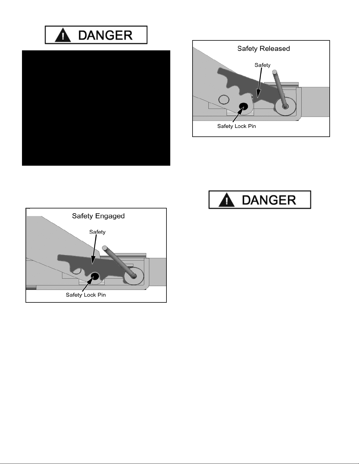
DANGER !
IT IS THE RESPONSIBILITY OF THE OWNER /
INSTALLER OF THIS ROLLING BRIDGE JACK TO
ENSURE THAT THE LIFT UPON WHICH THE ROLLING
BRIDGE JACK IS INSTALLED HAS BEEN PROPERLY
INSTALLED ACCORDING TO THE MANUFACTURER’S
SPECIFICATIONS.

7
1. Carefully remove the crating and packing materials. CAUTION! Be careful when cutting steel banding material as
items may become loose and fall causing personal harm or injury.
IMPORTANT SAFETY INSTRUCTIONS !
Read these safety instructions entirely!
IMPORTANT NOTICE !
Do not attempt to install this lift if you have never been trained on basic automotive lift installation procedures.
Never attempt to lift components without proper lifting tools such as forklift or cranes.
Stay clear of any moving parts that can fall and cause injury.
INTRODUCTION
1. READ AND UNDERSTAND all safety warning
procedures before operating jack.
2. KEEP HANDS AND FEET CLEAR. Remove hands and
feet from any moving parts. Keep feet clear of lift when
lowering. Avoid pinch points.
3. KEEP WORK AREA CLEAN. Cluttered work areas
invite injuries.
4. Consider work area environment. Do not expose
equipment to rain. DO NOT use in damp or wet locations.
Keep area well lighted.
5. ONLY TRAINED OPERATORS should operate this lift.
All non-trained personnel should be kept away from work
area. Never let non-trained personnel come in contact with,
or operate lift.
6. USE LIFT CORRECTLY. Use lift in the proper manner.
Never use lifting adapters other than what is approved by the
manufacturer.
7. DO NOT override self-closing lift controls.
8. REMAIN CLEAR of lift when raising or lowering vehicle.
9. CLEAR AREA if vehicle is in danger of falling.
10. ALWAYS INSURE that the safeties are engaged before
any attempt is made to work on or near vehicle.
11. DRESS PROPERLY. Non-skid steel-toe footwear is
recommended when operating lift.
12. DANGER! Shut off and disconnect the air
supply when installing the Rolling jack pump
and when the Pump is not in use or before
breaking any connections in the system.
13. MAINTAIN WITH CARE. Keep lift clean for better and
safer performance. Follow manual for proper lubrication and
maintenance instructions. Keep control handles and/or
buttons dry, clean and free from grease and oil.
14. STAY ALERT. Watch what you are doing. Use common
sense. Be aware.
15. CHECK FOR DAMAGED PARTS. Check for alignment
of moving parts, breakage of parts or any condition that may
affect its operation. Do not use lift if any component is broken
or damaged.
16. NEVER remove safety related components from the lift.
Do not use lift if safety related components are damaged
or missing.

8
STEP 1
(Verifying Lift Installation)
Before installing your new Rolling Bridge Jack, verify the
following aspects of the installation of the lift where Rolling
Bridge Jacks are being installed. The aspects of the lift
installation that need to be verified should include, but are
not limited to;
1. LIFT LOCATION / PROPER ALIGNMENT
2. OVERHEAD OBSTRUCTIONS.
3. CORRECT FLOOR COMPOSITION/
REQUIREMENTS.
4. OPERATING TEMPERATURE.
5. INDOOR INSTALLATION ONLY.
6. OPERATION MANUALS ON HAND .
7. OPERATORS PROPERLY TRAINED.
OPERATING TEMPERATURE.
Operate Rolling Bridge Jack only between
temperatures of 41° -104° F.
STEP 2
(Rolling Jack Capacities)
THE MAXIMUM LIFTING CAPACITY OF
THESE JACKS ARE DESCRIBED BELOW.
DANGER !
IT IS THE RESPONSIBILITY OF THE OWNER /
INSTALLER OF THIS ROLLING BRIDGE JACK TO
ENSURE THAT THE LIFT UPON WHICH THE ROLLING
BRIDGE JACK IS INSTALLED HAS BEEN PROPERLY
INSTALLED ACCORDING TO THE MANUFACTURER’S
SPECIFICATIONS.
IMPORTANT NOTE!
These instructions must be followed to insure proper installation and operation of your Rolling Bridge
Jack. Failure to comply with these instructions can result in serious bodily harm and void product
warranty. Manufacturer will assume no liability for loss or damage of any kind, expressed or implied
resulting from improper installation or use of this product.
PLEASE READ ENTIRE MANUAL PRIOR TO INSTALLATION !
Hex-Key / Allen Wrench Set
Medium Crescent Wrench
Shop Crane or other heavy lifting device
Medium Flat Screwdriver
Tape Measure: @ 25 Foot
Air Fitting (to connect air supply)
TOOLS REQUIRED
MODEL MAX JACK
CAPACITY
MAX VEHICLE WEIGHT
FRONT AXLE
MAX VEHICLE WEIGHT
REAR AXLE
RJ-45/S 4,500 Lbs/ 2,041 Kgs 4,500 Lbs/ 2,041 Kgs 4,500 Lbs/ 2,041 Kgs
RJ-6 6,000 Lbs / 2,721 Kgs 6,000 Lbs / 2,721 Kgs 6,000 Lbs / 2,721 Kgs
RJ-7 7,000 Lbs / 3,175 Kgs 7,000 Lbs / 3,175 Kgs 7,000 Lbs / 3,175 Kgs
RJ-9 9,000 Lbs / 4,082 Kgs 9,000 Lbs / 4,082 Kgs 9,000 Lbs / 4,082 Kgs
RJ-12 12,000 Lbs / 5,443 Kgs 12,000 Lbs / 5,443 Kgs 12,000 Lbs / 5,443 Kgs
RJ-15 15,000 Lbs / 6,804 Kgs 15,000 Lbs / 6,804 Kgs 15,000 Lbs / 6,804 Kgs
RJ-18 18,000 Lbs / 8,165 Kgs 18,000 Lbs / 8,165 Kgs 18,000 Lbs / 8,165 Kgs
RJ-25 25,000 Lbs / 11,340 Kgs 25,000 Lbs / 11,340 Kgs 25,000 Lbs / 11,340 Kgs
DANGER !
The AXLE WEIGHT of the vehicle being raised should
not exceed the maximum capacity of the Rolling Bridge
Jack. Consult the vehicle manufacturer for
specifications.
NOTE: An air supply (125 PSI Minimum / 10-20 CFM Minimum) will be required for operation.

9
Fig. 3.1
STEP 3
(Adjusting Lift / Jack Orientation)
1. Following the manufacturer’s instructions in the lift
manual. Lower the lift to the ground. (If using a shop crane,
you may need to lock the lift on the first Safety Lock to
make room for the legs of the Shop Crane.)
2. If adjustable, adjust the Runway of the lift to the
desired width. Be sure to check the specifications of the
lift and the Rolling Bridge Jacks to be sure that the Rolling
Bridge Jack can be adjusted to the desired Runway width.
(See Fig. 3.1 & 3.2)

10
Fig. 3.2

11
STEP 4
(Installing Jack on Rail)
1. Lower the Rolling Bridge Jack all the way down.
2. Using a shop crane, forklift or other lifting device raise
the Rolling Bridge Jack and place it in between the
Runways. (See Fig. 4.1)
3. Lower the Rolling Bridge Jack to just above the Utility
Rails on the inside of the Runways.
4. Adjust the Rolling Bridge Jack arms to the correct
width. (See Fig. 4.2)
NOTE: 18-25K models do not have adjustable arms.
5. When the desired width is reached. Lower the
Rolling Bridge Jack into the Utility Rails. Double check
that the Rollers are seated properly in or on the Utility
Rails. (See Fig. 4.3 & 4.4)
6. Ensure that the Utility Rail Channel is clean of debris,
tools etc.
7. Repeat the process for the other Rolling Bridge Jack
if installing in pairs.
8. Raise the lift up off the ground so that the Rolling
Bridge Jack is off the ground and lower the lift onto the
first safety stop.
ENSURE THAT THE LIFT IS RESTING ON THE
SAFETIES BEFORE PROCEEDING.
9. Check the clearance and movement of the Rolling
Bridge Jack by sliding the Rolling Bridge Jack forward
and rearward on the rails. Check that the Rollers are
centered on the Rails at all points along the rail’s length.
Adjustment of the Rolling Bridge Jack Arms or the
Runway width may be necessary to assure proper
operation.
WARNING!
When removing or moving the Rolling Bridge Jack
from shipping pallet pay close attention as the Jack
may move and can cause injury.
Prior to removing the strapping or bolts make sure
the Jack is held securely by a fork lift or some other
heavy lifting device.
Fig. 4.1
Fig. 4.2
Fig. 4.3
Fig. 4.4

12
STEP 5
(Connecting Air Supply)
Refer to page 18 if installing with the Optional Rolling
Bridge Jack Airline Kit.
1. Remove the thread protector from the air inlet of the
Pump. Select and install the threaded fittings (not
supplied) which are compatible with your air supply
fittings. The air supply should be 20 CFM / 57 M3/MIN)
and 100 PSI (7 BAR) to obtain the rated hydraulic pressure.
Air Supply should be regulated to a maximum of 125 PSI (8.6
BAR) (See Fig. 5.1)
2. An appropriate air line regulator, water separator and
lubricator should be installed on the Air Supply line. The
absence of these items will void the warranty on pneumatic
components. (See Fig. 5.2)
STEP 6
(Start Up / Final Adjustments)
1. Raise the Jack WITHOUT a vehicle to check for proper
operation of the Rolling Bridge Jack.
2. Depress the Pedal on the lifting end to raise the Jack
through the full range of the Jack. (See Fig. 6.1)
Under certain circumstances it may be necessary to prime
the Air Hydraulic Pump Unit. Refer to the manual that came
with the pump for these instructions.
3. Lower the Jack onto the nearest Safety Stop Pin. When
the Jack is loaded with a vehicle make sure the Jack is
resting on the Safety Stop Pin prior to performing any work
on the vehicle. (See Fig. 6.2)
DANGER!
THE AIR SUPPLY SHOULD BE TO
20 CFM (.57 M3/MIN.) AND 100 PSI (7 BAR).
AIR SUPPLY SHOULD BE REGULATED TO A
MAXIMUM OF 125 PSI (8.6 BAR)
DANGER!
DISCONNECT AND / OR RELEASE THE PRESSURE
FROM THE AIR SUPPLY SYSTEM / HOSES BEFORE
PERFORMING ANY INSTALLATION OR MAINTENANCE
OF THE AIR SUPPLY SYSTEM.
DANGER!
VISUALLY CONFIRM THAT ALL PRIMARY
SAFETY LOCKS ARE ENGAGED BEFORE
ENTERING WORK AREA.
Suspension components used on this Jack are
intended to raise and lower the Jack only and are not
meant to be load holding devices. Remain clear of
elevated Jack unless visual confirmation is made that
all primary Safety Locks are fully engaged and
the lift is LOWERED onto the Safety Locks.
Refer to installation /operation manual for proper
Safety Lock procedures and /or further instruction.
Fig. 5.1
Fig. 5.2
Fig. 6.1
Fig. 6.2

13
To lower the Rolling Bridge Jack;
When lowering the Jack PAY CAREFUL ATTENTION
that all personnel and objects are kept clear. ALWAYS
keep a visual line of site on the Jack AT ALL TIMES.
1. Raise the lift up so that the Safety is off the Safety
Stop Pin.
2. Flip the Safety Handle up Off the Safety Stop Pin.
(See Fig. 6.3)
3. Press the Pedal on the lowering end. Note: the Pedal
can lock in the lowering position to facilitate lowering of
the Jack. (See Fig. 6.4)
POST-INSTALLATION CHECK-OFF
Check For Hydraulic Leaks
Check Oil Level
Lubrication of Critical Components
Check For Overhead Obstructions
Runways Level
All Screws, Bolts, and Pins Secured
Surrounding Area Clean
Operation, Maintenance and Safety Manuals on Site
STEP 7
(Operation)
1. Load the vehicle on the lift, following the
manufacturer’s instructions.
To Raise the Jack:
2. Position vehicle tires in the center of each runway.
3. Set parking brake or use wheel chock to hold vehicle
in position.
4. Before raising vehicle, be sure all personnel are clear
of the lift and surrounding area. Pay careful attention to
overhead clearances. Determine the proper lift points on
the vehicle by referring to the manufacture’s specification or
an approved lifting guide.
5. Check and keep clean the Utility Rails channels
clean of debris, tools, or other objects that may hinder the
movement of the Rolling Jacks.
6. Adjust the Rolling Jack Arms so that the lift pads will
make contact with the appropriate lifting points on the
vehicle as specified by the manufacturer of the vehicle.
(See Fig. 7.1)
7. Raise the Rolling Bridge Jack by pushing on the
Raise end of the pedal of Air Hydraulic pump. Keep an
eye on the jack as the Lift pads make contact with the
vehicle to ensure that proper contact is maintained as the
weight of the vehicle is supported by the Jack.
8. Stop raising the jack just as the vehicle is raised off
the lift runways. Confirm the vehicle is stable and properly
seated before lifting the vehicle to the final desired height.
WARNING!
NEVER USE MORE THAN 5 INCHES OF
LIFT PAD ADAPTER HEIGHT.
Fig. 6.3
Fig. 6.4
Fig. 7.1

14
8. After vehicle is raised to the desired height, lower the
lift onto the nearest safety lock. ALWAYS INSURE ALL
SAFETY LOCKS ARE ENGAGED before entering work
area. (See Fig. 7.2)
To Lower Jack:
1. Before lowering vehicle, be sure all personnel are
clear of the lift and surrounding area. Pay careful
attention to overhead clearances. Insure all tools and
equipment have been cleared from under the Jack.
2. Raise the Jack off of the Safety Locks by pressing
the push button on the Power Unit. Make sure you raise
the Jack to allow adequate clearance for the Locks to
clear.
3. Flip the Safety Handle up to raise the Safety off the
Safety Lock Pin. (See Fig. 7.3)
4. Push the Lowering side of the Pedal on the Air
Hydraulic Pump until the lift has descended completely.
When lowering the lift PAY CAREFUL ATTENTION that
all personnel and objects are kept clear. ALWAYS keep
a visual line of site on the lift AT ALL TIMES.
DANGER!
VISUALLY CONFIRM THAT ALL PRIMARY
SAFETY LOCKS ARE ENGAGED BEFORE
ENTERING WORK AREA.
Suspension components used on this Jack are
intended to raise and lower Jack only and are not
meant to be load holding devices. Remain
clear of elevated Jack unless visual confirmation
is made that all primary Safety Locks are fully
engaged and the lift is LOWERED onto the
Safety Locks, Refer to installation /operation
manual for proper Safety Lock procedures
and /or further instruction.
Fig. 7.2
Fig. 7.3

15
WEEKLY MAINTENANCE
1. Lubricate all rollers with general purpose oil or
WD-40.
2. Check all Hose connections, bolts and pins to insure
proper mounting.
3. Lubricate Safety lock pivot points with general
purpose oil or WD-40.
4. Check and tighten Cylinder Bolt. (See Fig. 7.4)
MONTHLY MAINTENANCE
1. Lubricate the Cylinder Pin and Main Hinge Pin with
all purpose grease using a needle point lube coupler.
(See Fig. 7.5 & 7.6)
2. Check Safety Locks to insure they are in good
operating condition.
3. Make a visual inspection of ALL MOVING PARTS
and check for excessive signs of wear.
4. Replace ALL FAULTY PARTS before lift is put back
into operation.
NEVER EXCEED THE RATED CAPACITY of lift.
DO NOT USE LIFT if any component is found to be
defective or worn.
NEVER OPERATE LIFT with any person or
equipment below.
ALWAYS STAND CLEAR of lift when lowering or
raising.
ALWAYS INSURE SAFETY LOCKS ARE
ENGAGED before entering work area.
NEVER LEAVE LIFT IN ELEVATED CONDITION
unless all four safety locks are engaged.
Fig. 7.4
Fig. 7.5
Fig. 7.6

16

17
Safe Lift Operation
Automotive and truck lifts are critical to the operation and profitability of your business. The safe use of this and other
lifts in your shop is critical in preventing employee injuries and damage to customer’s vehicles. By operating lifts safely
you can insure that your shop is profitable, productive and safe.
Safe operation of automotive lifts requires that only trained employees should be allowed to use the lift.
TRAINING SHOULD INCLUDE, BUT NOT LIMITED TO:
Proper positioning of the vehicle on the runway. (See manufacturers minimize wheel base loading requirements.)
Use of the operating controls.
Understanding the lift capacity.
Proper use of jack stands or other load supporting devices.
Proper use, understanding and visual identification of safety lock devices and their operation.
Reviewing the safety rules.
Proper housekeeping procedures (lift area should be free of grease, oil, tools, equipment, trash, and other debris).
A daily inspection of the lift should be completed prior to its use. Safety devices, operating controls, lift arms and
other critical parts should be inspected prior to using the lift.
All maintenance and repairs of the lift should be completed by following the manufacturer’s requirements. Lift repair
parts should meet or exceed OEM specifications. Repairs should only be completed by a qualified lift technician.
The vehicle manufacturer’s recommendations should be used for spotting and lifting the vehicle.
LIFT OPERATION SAFETY
It is important that you know the load limit. Be careful that you do not overload the lift . If you are unsure what the
load limit is, check the data plate found on one of the lift columns or contact the manufacturer.
The center of gravity should be followed closely to what the manufacturer recommends.
Always make sure you have proper overhead clearance. Additionally, check that attachments, (vehicle signs,
campers, antennas, etc.) are not in the way.
Be sure that prior to the vehicle being raised, the doors, trunk, and hood are closed securely.
Prior to being raised, make sure there is no one standing closer than six feet from the lift.
After positioning the vehicle on the lift runways, set the emergency brake, make sure the ignition is off, the doors are
closed, overhead obstructions are cleared, and the transmission is in neutral.
Double check that the automatic chock devices are in position and then when the lift is raised, observe the chocks
Put pads or adapters in the right position under the contact points that have been recommended.
The lift should be raised just until the vehicle’s wheels are about one foot off the ground. If contact with the vehicle is
uneven or it appears that the vehicle is not sitting secure, carefully lower the lift and readjust.
Always consider potential problems that might cause a vehicle to slip, i.e., heavy cargo, undercoating, etc.
Pay attention when walking under a vehicle that is up on the hydraulic lift.

DO NOT leave the controls while the lift is still in motion.
DO NOT stand directly in front of the vehicle or in the bay when vehicle is being loaded or driven into position.
DO NOT Go near vehicle or attempt to work on the vehicle when being raised or lowered.
REMAIN CLEAR of lift when raising or lowering vehicle.
DO NOT rock the vehicle while on the lift or remove any heavy component from vehicle that may cause excessive
weight shift.
DO NOT lower the vehicle until people, materials, and tools are clear.
ALWAYS INSURE that the safeties are engaged and lowered on to the safety ladders before any attempt is made to work
on or near vehicle.
Some vehicle maintenance and repair activities may cause the vehicle to shift. Follow the manufacturer’s guidelines
when performing these operations. The use of jack stands or alternate lift points may be required when completing
some repairs.
READ AND UNDERSTAND all safety warning procedures before operating lift.
KEEP HANDS AND FEET CLEAR. Remove hands and feet from any moving parts. Keep feet clear of lift when lowering.
Avoid pinch points.
ONLY TRAINED OPERATORS should operate this lift. All non-trained personnel should be kept away from work area.
Never let non-trained personnel come in contact with, or operate lift.
USE LIFT CORRECTLY. Use lift in the proper manner. Never use lifting adapters other than what is approved by the
manufacturer.
DO NOT override self-closing lift controls.
CLEAR AREA if vehicle is on danger of falling.
STAY ALERT. Watch what you are doing. Use common sense. Be aware.
CHECK FOR DAMAGED PARTS. Check for alignment of moving parts, breakage of parts or any condition that may
affect its operation. Do not use lift if any component is broken or damaged.
NEVER remove safety related components from the lift. Do not use lift if safety related components are damaged or
missing.
When the lift is being lowered, make sure everyone is standing at least six feet away.
Be sure there are no jacks, tools, equipment, left under the lift before lowering.
Always lower the vehicle down slowly and smoothly.
18

19
HD-9-12,12X,14,14X Series Rolling Jack
Air Line Installation Kit Part # 5174009
REV 06-04-09
NOTE:
Holes in the runways for the integrated air line kit may have been an optional modification on some lift models.
Contact BendPak technical support for assistance if adding Rolling Jacks /Air Line Kit after purchase.
Optional Integrated Air Line Kit for Rolling Bridge Jacks
(HD-9-12X-14 Kit shown. Contact Your BendPak Dealer for kits for other lift models.)

20
This manual suits for next models
7
Table of contents
Other Bend-Pak Jack manuals