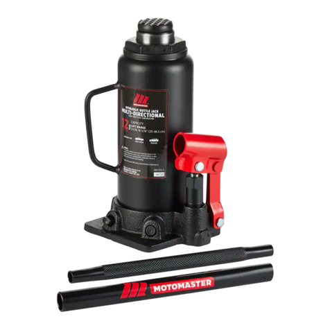
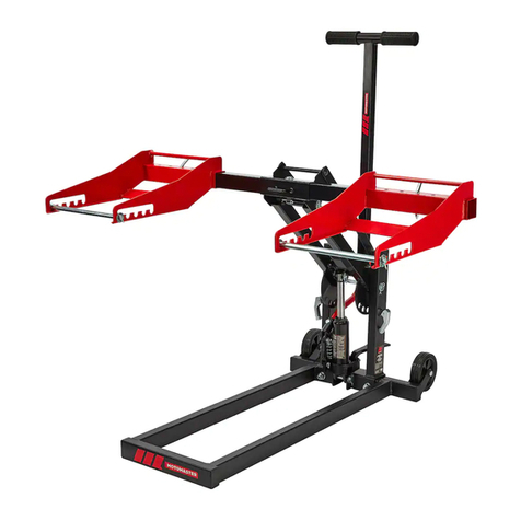
Motomaster 009-1011-0 User manual

HYDRAULIC /
PNEUMATIC JACK
model no. 009-1011-0
IMPORTANT:
To prevent serious injury, read and understand all warnings and instructions before use.

2
IF ANY PARTS ARE MISSING DAMAGED, OR IF YOU HAVE ANY
QUESTIONS, PLEASE CALL OUR TOLL-FREE HELPLINE AT
1-888-942-6686
Read and understand this instruction manual thoroughly before using the product. It
contains important information for your safety as well as operating and maintenance
advice.
Keep this instruction manual for future use. Should this product be passed on to a third
party, this instruction manual must be included.
The English version of this manual is available online at:
www.canadiantire.ca/manuals
INFORMATION
1-888-942-6686
009-1011-0
Tested to the latest ANSI safety
and performance requirements.

3
TABLE OF CONTENTS
SAVE THESE INSTRUCTIONS
This manual contains important safety and operating instructions. Read all instructions and follow
them while using the product.
TABLE OF CONTENTS
General Safety Precautions 4
Warranty 16
14
Assembly 8
Unpacking 8
Checking hydraulic uid 8
Before operating this lift 8
Specications 4
Unpacking 8
Hydraulic Jack Assembly Diagram
9
Bleeding the System
Operation 10
12
Maintenance
Troubleshooting
Hydraulic Jack Parts List
13
15

1-888-942-6686
009-1011-0
SPECIFICATIONSGENERAL SAFETY PRECAUTIONS
SPECIFICATIONS
GENERAL SAFETY PRECAUTIONS
• Read instruction manual before use.
• Keep your work area clean and well lit. Cluttered work areas invite accidents.
• Keep bystanders, children and visitors away while operating jack. Distractions
can cause you to lose control. Protect others in the work area.
• Stay alert. Use common sense when operating a jack. Do not use a jack while tired
or under the inuence of drugs, alcohol, or medication. A moment of inattention
while operating jacks may result in serious personal injury.
• Dress properly. Do not wear loose clothing or jewellery. Contain long hair. Keep
your hair, clothing, and gloves away from moving parts. Loose clothes, jewellery,
or long hair can be caught in moving parts.
• Do not overreach. Keep proper footing and balance at all times. Proper footing
and balance enables better control of the jack in unexpected situations.
• Use safety equipment. Always wear ANSI-approved safety impact goggles,
steel-toed safety shoes/boots, and heavy-duty work gloves when using this
product.
• Do NOT force the jack. Use the correct jack for your application. The correct jack
will do the job better and safer at the rate for which it is designed.
4
Construction Formed Steel over Maximum Lifting 12 Tons (10,884 kg)
Hydraulic action Capacity
Lift Range 10 1/4 - 20 1/8" Screw Extension 3 5/32" (8 cm)
(26 - 51 cm)
Hydraulic Lift 6 3/4" (17 cm) Overall Base 8 1/2" (21.6 cm) L x 5
Dimensions 1/2" (14 cm) W
Air Fitting 1/4" NPT with quick Hose Size 1/2" (1.3 cm) O.D. x
release nipple 49" (125.5 cm) L
Operating Pressure 100 - 120 PSI Net Weight 26 lb 7 oz (12 kg)
WARNING!
READ AND UNDERSTAND ALL INSTRUCTIONS.
Failure to follow all instructions listed in the following pages may result in electric shock, re,
and/or serious injury. SAVE THESE INSTRUCTIONS.

5
• Store idle jacks out of reach of children and other untrained persons. Jacks are
dangerous in the hands of untrained users.
• Maintain jacks with care. Do not use a damaged jack. Tag damaged jacks and do not
use until repaired.
• If damaged, have the jack serviced before using. Check for loose screws, misalignment
or binding of moving parts, loose mounting, cracked or broken parts, low hydraulic oil
level, and any other condition that may affect its safe operation. Many accidents are
caused by poorly maintained jacks.
• Jack service must be performed only by qualied repair personnel. Service or
maintenance performed by unqualied personnel could result in a risk of injury.
• When servicing a jack, use only identical replacement parts. Refer to the Parts List on
page 15 and Assembly Diagram on page 14 of this manual. Use of unauthorized
parts or failure to follow maintenance instructions may create a risk of injury.
• The jack is designed for intermittent use only. Do NOT use the jack to support a vehicle
over extended periods of time. The duration of the lifting job should be kept as short as
possible. Always use jack stands to support a vehicle over an extended period of time.
• Maintain labels and nameplates on the jack. These carry important information. If unreadable
or missing, contact customer service for a replacement.
• Prior to using the jack, make sure to read and understand all warnings, safety precautions,
and instructions as outlined in the manufacturer’s instruction manual for the vehicle (or object)
you will lift.
• When lifting only one wheel, make sure to support the load immediately with one jack stand
(not included) placed under the side of the vehicle being lifted. Align the saddle of the jack
stand directly under the vehicle’s seam or recommended lifting point.
• When lifting the entire front end or rear end of a vehicle, make sure to support the load
immediately with two jack stands. Align the saddles of the jack stands directly under the
vehicle’s frame or recommended lifting points. Also make sure the jack stands are adjusted
at the same height.
GENERAL SAFETY PRECAUTIONS
WARNING!
Do not exceed the maximum lift capacity for the jack as stated on the product label and the
specications table. Overloading the jack could cause serious personal injury and/or property
damage.

. 009-0037-6 1-888-942-6686
009-1011-0
6
• Make sure the jack is used only on a dry, oil/grease-free, at, level, solid surface
capable of supporting the weight of the vehicle being lifted and any additional tools
and equipment.
• Use the jack only on vehicles whose frames have lifting points (on their seam or frame)
capable of aligning with the saddle of the jack.
• This jack is not intended for roadside use. This jack requires a at, stable surface to
safely lift a load.
• Do not use the jack with the vehicle’s engine running. Make sure to place the vehicle’s
transmission in “Park” (if automatic) or rst gear (if manual). Then set the emergency
brake, and chock the tires opposite the tire being lifted.
• Industrial applications must follow OSHA requirements.
• Always keep hands, ngers, and feet away from all moving parts of the jack when
applying or releasing a load. Remain clear of the vehicle being raised or lowered.
People and animals should be kept at a safe distance when using the jack.
• Use extreme caution when applying or releasing a load. Never allow the load to
suddenly release. Slowly and carefully apply and release the load.
• Do not allow anyone in the vehicle while using the jack. Keep all bystanders a safe
distance away from the vehicle.
• Never leave the jack unattended when the jack is under a load.
• Never support both ends of the vehicle at the same time.
• Before lowering the jack, make sure tool trays, jack stands, and all other tools and
equipment are removed from under the vehicle.
• Do not stand on the jack as it may tip, causing personal injury.
• If changing a damaged tire, make it easier to remove the lug nuts by slightly loosening
the lug nuts before raising the tire off the ground.
• This jack is not to be used for aircraft purposes. Never modify the jack in an attempt
to use it for a purpose it was not designed for.
• Never adjust the factory set safety valve.
• Compressed air only. Never use compressed gas as a power source for this item.
GENERAL SAFETY PRECAUTIONS
WARNING!
Do not work under the vehicle without properly supporting the vehicle with jack stands.
Make sure the load and jack stands are stable before getting under a vehicle.

GENERAL SAFETY PRECAUTIONS
7
• Lift vehicle only by manufacturer-recommended lifting points.
• Stay out from under load while being lifted or supported.
• Bleed hydraulic system before use.
• Use only for lifting.
• Do not exceed the maximum air pressure. Capacity for this jack is 120 PSI.
• Avoid rapid load descents; turn the valve release screw slowly.
WARNING!
The warnings, precautions, and instructions discussed in this manual cannot cover all possible
conditions and situations that may occur. The operator must understand that common sense and
caution are factors which cannot be built into this product, but must be supplied by the operator.

. 009-0037-6 1-888-942-6686
009-1011-0
UNPACKING
8
UNPACKING
When unpacking, check for damage. If any parts are missing or broken, please call
Customer Service at the number on the cover of this manual.
• Hydraulic/Pneumatic Jack
• Attached 49" air hose with ttings
• 2-piece jack handle
Please refer to the Assembly Diagram and Part Lists on page 14-15 of this manual for
other parts information.
ASSEMBLY
•Apply thread seal tape (not included) to the threads and screw the air hose (40) into
the base (1).
•Apply thread seal tape (not included) to the threads and screw the air valve (52) onto
the air hose (40).
•Connect both parts of the handle (54). insert it into the handle bracket (31)-see
Figure 1 on page 9 and the Assembly Diagram on page 14.
BEFORE OPERATING THIS JACK
Before initial use, a pressurized air supply must be furnished. The hydraulic uid level
must also be checked before use. Then thoroughly test the jack for proper operation prior
to its actual use. If the jack appears not to be working properly, it may be necessary to
bleed its hydraulic system of excess air.
CHECKING HYDRAULIC FLUID
Air bubbles can become trapped inside the hydraulic system thereby reducing the
efciency of the jack. Purge the air from the system if lift efciency drops.
•Place the slotted end of the jack handle (54) assembly over the release valve (4) and
turn 1-1/2 turns counter-clockwise.
•Remove the oil ller plug (16) on the side of the jack reservoir (15) by gently turning
counter-clockwise.
•Rapidly pump the handle assembly several times to purge the air from the hydraulic
system.
• Turn the release valve screw clockwise until snug using the handle assembly.
•Top up jack reservoir (15) with a high quality hydraulic jack oil as described on page 12.
•Replace the oil ller plug (16).
NOTE:
Before rst using this tool, the hydraulic ram may need to be purged. Some air may intrude in the
hydraulic system due to movement during shipping.

BLEEDING THE SYSTEM
BLEEDING THE SYSTEM
• Remove the oil ller plug (16). Insert the slot on the lower portion of the handle (54)
over the release valve (4). Turn the handle assembly clockwise to close the
release valve (4).
• Insert the handle assembly into the handle bracket (31). Pump the handle (54)
10-15 times.
• Connect the air supply to the air inlet hose. Squeeze the air valve and allow it to
operate for one minute. Disconnect the air supply.
• Once air is bled, check the reservoir (15) and, if necessary, top up the reservoir with
hydraulic oil. Then, replace the oil ller plug.
• Test the jack several times for proper operation before attempting to lift a load. If,
after bleeding, the jack still does not appear to be working properly, do not use the
jack until it has been repaired by a qualied service technician.
9
Oil Filler
Plug (16)
Flgure 2
Handle (54)
Handle
Bracket (31)
Release
Valve (4)
Spring
Plate (20)
Flgure 1

. 009-0037-6 1-888-942-6686
009-1011-0
OPERATION
OPERATION
• Verify that the vehicle’s weight is not more than the weight capacity for this jack.
• Check to make sure the jack is fully lowered. If not, insert the lower portion of the
handle into the release valve and turn the handle counter-clockwise to lower the
jack. Once the jack is fully lowered, turn the handle rmly clockwise to close the
release valve.
• Adjust the extension screw (13.1) as needed to position it directly underneath
the lifting point. Turn it counter-clockwise to raise, or clockwise to lower.
• Lifting using pressurized air power:
a. Connect the air supply hose (40). The lock lever (41) should be in the OFF
(not locked) position.
b. Connect the air compressor (compressor not included, must supply at least
7 CFM at 100-120 PSI) to the air supply hose.
c. Turn the compressor on and allow it to pressurize, if not already pressurized.
d. Press the lever (42) to the ON position and lock it into place using the lock lever
(41). This will provide a continuous air supply to the air motor (39), raising the
jack.
e. Position the jack on a solid level surface that can withstand the weight of the jack
and the load which will be lifted.
f. Be sure the load is balanced on the jack. Sturdy jack stands (not included)
positioned under the weight provide a good safety precaution against the possibility
of the load topping.
g. Be sure that the jack is positioned at a proper lift point on the item to be lifted.
Using appropriate lift points avoids possible damage to the item. Rotate the screw
extension (13.1) on the ram (13) until it contacts the underside of the load to be lifted.
Screwing counter-clockwise raises the extension, screwing clockwise lowers the
extension.
• Lifting manually:
To manually operate the jack without using compressed air, close the release valve,
then insert the end of the jack handle (54) into the handle bracket (31) and pump up
and down. This action will raise the jack.
• Support the load using jack stands (not included) or other means to support the weight.
Do not leave the load on the jack for an extended period of time. Damage to the jack or
property or personal injury may result.
WARNING!
Make sure the vehicle is parked on a at, level, solid surface. Turn off the vehicle’s engine.
Place the vehicle’s transmission in “PARK” (if automatic) or in rst gear (if manual). Set the
vehicle’s emergency brake. Then, chock the wheels that are not being lifted.
10

• To lower the item, rst lift the item slightly and remove the jack stands.
• Engage notches in the end of the jack handle (54) onto the release valve (4).
Turn the valve slightly, approximately 1/4 turn to lower the load. When the load is
lowered, turn the release valve clockwise to stop the motion.
• Lowering the jack
a. Make sure the lock lever (41) is released to stop the air ow to the air motor (39).
b. If attached, remove the air supply hose (40) from the air inlet tting.
c. Place the slotted end of the handle (54) onto the release valve.
d. Slowly and carefully lower the load by turning the release valve counter-clockwise
in very small increments. Only use the handle (54), never use your hand to turn
the release valve.
e. Lower the extension screw (13.1) as needed by turning clockwise.
f. Remove the jack.
CAUTION:
Avoid rapid descent of the load by turning the release valve slowly.
OPERATION
11

1-888-942-6686
009-1011-0
MAINTENANCE
12
MAINTENANCE
• Oil Replacement
a. Place the jack in an upright position.
b. Completely lower the ram (13). Remove the oil ller plug (16).
c. Fill with high quality hydraulic jack oil to the lower rim of the ll hole.
d. Purge the air from the hydraulic system as previously described.
e. Top off with hydraulic oil.
f. Replace the oil ller plug (16).
• Before each use, inspect the general condition of the jack. Check for broken,
cracked, or bent parts, loose or missing parts, and any condition that may affect
the proper operation of the product. If a problem occurs, have the problem corrected
before further use. Do not use damaged equipment.
• Before each use, make sure to thoroughly test the jack for proper operation prior to
its actual use. If the jack appears not to be working properly, it may be necessary to
bleed its hydraulic system of excess air. Refer to page 9 for complete instructions
on bleeding the system.
• Change the hydraulic oil at least once every three years. to do so, with the jack fully
lowered, remove the oil ller plug on the side of the reservoir. Tip the jack to allow
the old hydraulic oil to drain out of the reservoir completely, and dispose of the old
hydraulic oil in accordance with local regulations. with the jack upright, completely
ll the reservoir with a high quality hydraulic oil (not included) until the oil just begins
to spill out of the oil ll hole. Then, reinstall the oil ller plug.
• When cleaning, use a clean cloth with a detergent or mild solvent. Then, store the
jack in a safe, dry location out of reach of children and other non-authorized people.
WARNING!
All maintenance, service, or repairs not listed in this manual are only to be attempted by a
quailed service technician.

TROUBLESHOOTING
13
TROUBLESHOOTING
• If the jack fails to lift, or fades under the load, rst check that the release valve (4) is
closed. Engage the notches at the end of the jack handle (54) onto the release
valve (4) and turn clockwise. Check to see if this has solved the problem.
• Next check to see if there are any leaks in the air system. Examine all connections
and valves to see if there is a leak. If so, have a qualied service technician repair
the connection or replace the faulty part.
• Check to see if there are any leaks in the hydraulic system. Leaks will produce
visible hydraulic uid at the separation. If there are any leaks, have a qualied repair
technician tighten, repair or replace any leaking components.
• Air in the hydraulic system will cause the jack to fade. If no leaks are detected, bleed
the hydraulic system to remove any trapped air. Bleeding instructions are given on
page 9 of this manual.
• If none of these troubleshooting options solves the problem, it is possible that the
seals of the jack have been damaged by overloading, dirt on the ram or other
environmental factors. Have a qualied service technician inspect the jack for fault
and possible repair.

1-888-942-6686
009-1011-0
HYDRAULIC JACK ASSEMBLY DIAGRAM
14
NOTE:
Some parts are listed and shown for illustration purposes only and are not available individually as
replacement parts.

HYDRAULIC JACK PARTS LIST
15
HYDRAULIC JACK PARTS LIST
No. Description Qty. No. Description Qty.
1 Base 1
2 Ball 6
3 Seal 1
4 Release Valve 1
5 Ball Cup 2
6 Spring 1
7 Spring 1
8 Screw 2
9 Nylon Ring 1
10 Cylinder 1
11 O-ring 1
12 Cup Seal 1
13 Ram 1
13.1 Extension Screw 1
14 Gasket 1
15 Reservoir 1
16 Oil Filler Plug 1
17 Nylon Ring 1
18 Top Nut 1
19 O-ring 1
20 Spring Plate 1
21 Return Spring 2
22 Washer 2
23 Pump Cylinder 1
24 O-ring 1
25 Nylon Ring 1
26 Backup Ring 1
27 Piston 1
28 Pin 3
29 R-Pin 1
30 Connector 1
31 Handle Bracket 1
32 Ball 1
33 Ball Cup 1
34 Spring 1
35 Screw 1
36 O-ring 1
37 Screw 1
38 Plastic Cap 1
39 Air Motor Assembly 1
40 Air Supply Hose 1
41 Lock Lever 1
42 Lever 1
43 Nut 1
44 O-ring 1
45 O-ring 1
46 O-ring 1
47 O-ring 1
48 Throttle 1
49 Spring 1
50 Lock Nut 1
51 Bolt 1
52 Valve Body 1
53 Quick Coupler-Male 1
54 Handle 1
55 Strainer 1
56 Rotary Joint 1
57 R-Pin 2
58 Eye Bolt 2
59 Handle 1
60 lter holder 1
61 leter 1
62 O-ring 1

1-888-942-6686
009-1011-0
WARRANTY
This MotoMaster® product carries a one (1) year warranty against defects in workmanship
and materials. At its discretion, MotoMaster Canada agrees to have any defective part(s)
repaired or replaced free of charge, within the stated warranty period, when returned by
the original purchaser with proof of purchase. This product is not guaranteed against wear
or breakage due to misuse and/or abuse.
Made in China
Imported by MotoMaster Canada, Toronto, Canada M4S 2B8.
WARRANTY
16
even in a sealed container,
towards

Modèle no009-1011-0
GUIDE
D’UTILISATION
CRIC
HYDRAULIQUE/PNEUMATIQUE
IMPORTANT :
Pour réduire les risques de blessures graves, lisez et assimilez tous les avertissements et les
consignes avant l’utilisation.

2
RENSEIGNEMENTS SUR LA GARANTIE
SI VOUS AVEZ DES QUESTIONS AU SUJET DE CET ARTICLE, OU
SI DES PIÈCES SONT MANQUANTES OU ENDOMMAGÉES,
COMMUNIQUEZ AVEC NOTRE SERVICE D'ASSISTANCE
TÉLÉPHONIQUE SANS FRAIS AU 1-888-942-6686.
Veuillez lire attentivement et bien comprendre le présent guide avant d'utiliser cet
article. Celui-ci contient des informations importantes pour votre sécurité ainsi que
des conseils sur son fonctionnement et son entretien.
Conservez ce guide an de pouvoir vous y référer ultérieurement. Lorsque vous
cédez cet appareil à un tiers, remettez-lui également ce guide d'utilisation.
La version françaisee de ce guide est disponible en ligne à :
www.canadiantire.ca/guides
Modèle no009-1011-0 / Communiquez avec nous : 1-888-942-6686
Éprouvé selon les plus récentes exigences de
l'ANSI visant la sécurité et la performance.

3
CONSERVEZ CES CONSIGNES
Le présent guide contient d'importantes consignes de sécurité et de fonctionnement. Veuillez lire toutes les consignes
et les respecter pendant que vous utilisez cet article.
TABLE DES MATIÈRES
Consignes de sécurité générales 4
Garantie 16
Montage 8
Déballage 8
Vérication du liquide hydraulique 8
Avant d’utiliser ce cric 8
TABLE DES MATIÈRES
Fiche technique 4
Déballage 8
Schéma de montage du cric hydraulique
9
Purge du système
Fonctionnement 10
12
Entretien
Dépannage 13
14
Nomenclature du cric hydraulique 15

Modèle no009-1011-0 / Communiquez avec nous : 1-888-942-6686
FICHE TECHNIQUECONSIGNES DE SÉCURITÉ GÉNÉRALES
4
FICHE TECHNIQUE
CONSIGNES DE SÉCURITÉ GÉNÉRALES
Construction Prolé en tôle Capacité de charge 12 tonnes (10 884kg)
pliée sur action maximale
hydraulique Delete
Delete
Levée 10 1/4 à 20 1/8 po Vis de rallonge 3 5/32 po (8 cm)
(26 à 51 cm)
Portée du piston 6 3/4 po (17 cm) Dimensions 8 1/2 po (21,6 cm) L x
de la base 5 1/2 po (14 cm) I
Delete extra space 1/4 po NPT avec Taille du tuyau 1/2 po (1,3 cm) dia
here d’air mamelon à .ext. x
dégagement rapide 49 po (125,5 cm) L
Pression d’utilisation 100 à 120 lb/po² Poids net 26 lb 7 oz (12 kg)
AVERTISSEMENT!
LISEZ ATTENTIVEMENT TOUTES LES INSTRUCTIONS
Le non-respect de toutes les instructions gurant dans ce guide peut entraîner des chocs
électriques, un incendie ou des blessures graves. CONSERVEZ CES INSTRUCTIONS.
• Lisez le guide avant d'utiliser l'article.
• Gardez votre aire de travail propre et bien éclairée. Les aires de travail encombrées
sont propices aux accidents.
• Empêchez les personnes présentes, les enfants et les visiteurs de s’approcher
pendant que vous utilisez un cric. Toute distraction peut provoquer une fausse
manœuvre. Protégez ceux qui se trouvent dans l'aire de travail.
• Demeurez vigilant. Soyez attentif aux gestes que vous posez et faites preuve de bon
sens en utilisant un cric. N’utilisez pas de cric si vous êtes fatigué ou sous l’inuence
d’une drogue, de l’alcool ou d’un médicament. Un moment d’inattention pendant
l’utilisation d’un cric peut entraîner des blessures corporelles graves.
• Portez des vêtements convenables. Ne portez pas de vêtements amples ou de bijoux.
Attachez-vous les cheveux si vous les portez longs. Éloignez les cheveux, les
vêtements et les gants de toute pièce mobile. Les vêtements amples, les bijoux ou les
cheveux longs peuvent rester coincés dans une pièce mobile.
• Évitez de vous mettre en déséquilibre. Gardez un bon appui et un bon équilibre en
toute circonstance. Grâce à un appui et à un équilibre appropriés, vous serez mieux
en mesure de maîtriser le cric lors de situations inattendues.
• Utilisez un équipement de sécurité. Portez toujours des lunettes de sécurité résistantes
aux chocs approuvées par l’ANSI, des chaussures/bottes de sécurité à embout d’acier
et des gants de travail ultrarésistants lorsque vous utilisez cet article.
Table of contents
Languages:
Other Motomaster Jack manuals
Popular Jack manuals by other brands

ATD Tools
ATD Tools Atd-7430 Operating instructions & parts manual

Clarke
Clarke CTJ30 Operation and maintenance instructions

Strongarm
Strongarm SureWerx 728D owner's manual

Powerbuilt
Powerbuilt 640405 Operating and maintenance instruction manual

VEVOR
VEVOR TJD-12000SP-F quick start guide

Clarke
Clarke Strong-Arm CTJ4000G Operation & maintenance instructions