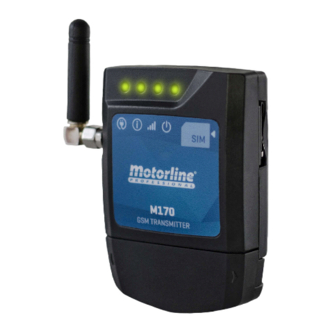
Motorline professional M175 User manual

V2.0
REV. 01/2020
M175
EN
USER'S/INSTALLER'S MANUAL

A B
2B
5A
5B
7A
6
7B
19
19
8A
18
17
17
8A
8B
9A
9B
9B
9B
10A
10A
12A
16B
10B
14A
13A
11A
14B
12B
11A
15B
15B
11B
16B
ENEN
. CONTENT
INDEX
01. SAFETY INSTRUCTIONS
This product is certified in accordance with European
Community (EC) safety standards.
This product complies with Directive 2011/65/EU of the
European Parliament and of the Council, of 8 June 2011, on
the restriction of the use of certain hazardous substances in
electrical and electronic equipment.
(Applicable in countries with recycling systems).
This marking on the product or literature indicates that the
product and electronic accessories (eg. Charger, USB cable,
electronic material, controls, etc.) should not be disposed
of as other household waste at the end of its useful life. To
avoid possible harm to the environment or human health
resulting from the uncontrolled disposal of waste, separate
these items from other types of waste and recycle them
responsibly to promote the sustainable reuse of material
resources. Home users should contact the dealer where they
purchased this product or the National Environment Agency
for details on where and how they can take these items
for environmentally safe recycling. Business users should
contact their vendor and check the terms and conditions
of the purchase agreement. This product and its electronic
accessories should not be mixed with other commercial
waste.
This marking indicates that the product and electronic
accessories (eg. charger, USB cable, electronic material,
controls, etc.) are susceptible to electric shock by direct or
indirect contact with electricity. Be cautious when handling
theproductandobserveallsafetyproceduresinthismanual.
ATTENTION:
DEVICE FUNCTIONS
TECHNICAL CHARACTERISTICS
WIRING AND FIXING
VISUAL ASPECT
CONNECTIONS
. SAFETY INSTRUCTIONS
. THE DEVICE
. INSTALLATION
INSTRUCTIONS FOR FINAL CONSUMERS
CONFIGURE M175 AS ALARM COMMUNICATOR
INSTRUCTIONS FOR SPECIALISED TECHNICIANS
CONFIGURE THROUGH SMS
. TROUBLESHOOTING
. USE AS ALARM
ACCESS PASSWORDS
REGISTER WITH microSD (OPTIONAL)
CONFIGURATION COMMANDS
SETTINGS LEGEND
RESPONSE SMS FORMAT
. PRECONFIGURATION
. ACCESS RECORD
RESTORE SETTINGS
ESSENTIAL CONFIGURATION STEPS
DEVICE NAME
SET UP SIM CARD NUMBER
SET UP ADMINISTRATOR PASSWORD
PRE-SET HOURS FOR CALLINGS OF USERS
CHECK LAST CALL
CONFIGURE CLOCK MANUALLY
ACTIVATE LIMIT TIME CONTROL
SET USER
RECOVER ADMINISTRATOR PASSWORD
CONFIGURE RELAYS
PRE-SET DAYS OF THE WEEK FOR CALLINGS OF USERS
CHECK GSM SIGNAL QUALITY
SET UP CONTACTS FOR FEEDBACK
RESTRICT RELAY 1 BY CALL
SET UP BLUETOOTH PAIRING TYPE
CHECK ENTRY STATUS 1 AND 2
. CONFIGURATION THROUGH SMS

EN
01. SAFETY INSTRUCTIONS
GENERAL WARNINGS
•This manual contains very important safety and usage information.
very important. Read all instructions carefully before beginning the
installation/usage procedures and keep this manual in a safe place
that it can be consulted whenever necessary.
•This product is intended for use only as described in this manual. Any
other enforcement or operation that is not mentioned is expressly
prohibited, as it may damage the product and put people at risk
causing serious injuries.
•Thismanualisintended firstly forspecializedtechnicians, and does not
invalidate the user’s responsibility to read the “User Norms” section in
order to ensure the correct functioning of the product.
•The installation and repair of this product may be done by qualified
and specialized technicians, to assure every procedure are carried
out in accordance with applicable rules and norms. Nonprofessional
and inexperienced users are expressly prohibited of taking any action,
unless explicitly requested by specialized technicians to do so.
•Installations must be frequently inspected for unbalance and the
wear signals of the cables, springs, hinges, wheels, supports and other
mechanical assembly parts.
•Do not use the product if it is necessary repair or adjustment is
required.
•When performing maintenance, cleaning and replacement of parts,
the product must be disconnected from power supply. Also including
any operation that requires opening the product cover.
•The use, cleaning and maintenance of this product may be carried
out by any persons aged eight years old and over and persons whose
physical,sensorialormentalcapacitiesarelower,orbypersonswithout
any knowledge of the product, provided that these are supervision
and instructions given by persons with experienced in terms of usage
of the product in a safe manner and who understands the risks and
dangers involved.
•Children shouldn’t play with the product or opening devices to avoid
the motorized door or gate from being triggered involuntarily.
WARNINGS FOR TECHNICIANS
•Before beginning the installation procedures, make sure that you have
all the devices and materials necessary to complete the installation
of the product.
•You should note your Protection Index (IP) and operating temperature
to ensure that is suitable for the installation site.
•Provide the manual of the product to the user and let them know how
to handle it in an emergency.
•If the automatism is installed on a gate with a pedestrian door, a door
locking mechanism must be installed while the gate is in motion.
•Do not install the product “upside down” or supported by elements do
not support its weight. If necessary, add brackets at strategic points
to ensure the safety of the automatism.
•Do not install the product in explosive site.
•Safety devices must protect the possible crushing, cutting, transport
and danger areas of the motorized door or gate.
•Verify that the elements to be automated (gates, door, windows,
blinds, etc.) are in perfect function, aligned and level. Also verify if the
necessary mechanical stops are in the appropriate places.
•The central must be installed on asafeplaceof anyfluid (rain, moisture,
etc.), dust and pests.
•You must route the various electrical cables through protective tubes,
to protect them against mechanical exertions, essentially on the
power supply cable. Please note that all the cables must enter the
central from the bottom.
•If the automatism is to be installed at a height of more than 2,5m from
the ground or other level of access, the minimum safety and health
requirements for the use of work equipment workers at the work of
Directive 2009/104/CE of European Parliament and of the Council of 16
September 2009.
•Attach the permanent label for the manual release as close as possible

EN
01. SAFETY INSTRUCTIONS
to the release mechanism.
•Disconnect means, such as a switch or circuit breaker on the electrical
panel, must be provided on the product’s fixed power supply leads in
accordance with the installation rules.
•If the product to be installed requires power supply of 230Vac or
110Vac, ensure that connection is to an electrical panel with ground
connection.
•The product is only powered by low voltage satefy with central (only
at 24V motors)
WARNINGS FOR USERS
•Keep this manual in a safe place to be consulted whenever necessary.
•If the product has contact with fluids without being prepared, it must
immediately disconnect from the power supply to avoid short circuits,
and consult a specialized technician.
•Ensure that technician has provided you the product manual and
informed you how to handle the product in an emergency.
•Ifthesystemrequiresanyrepairormodification,unlocktheautomatism,
turn off the power and do not use it until all safety conditions have
been met.
•In the event of tripping of circuits breakers of fuse failure, locate
the malfunction and solve it before resetting the circuit breaker or
replacing the fuse. If the malfunction is not repairable by consult this
manual, contact a technician.
•Keep the operation area of the motorized gate free while the gate in in
motion, and do not create strength to the gate movement.
•Do not perform any operation on mechanical elements or hinges if the
product is in motion.
RESPONSABILITY
•Supplier disclaims any liability if:
•Product failure or deformation result from improper installation
use or maintenance!
•Safety norms are not followed in the installation, use and
maintenance of the product.
•Instructions in this manual are not followed.
•Damaged is caused by unauthorized modifications
•In these cases, the warranty is voided.
SYMBOLS LEGEND:
• Important safety
notices
• Useful information
• Programming
information
• Potentiometer
information
• Connectors
information
• Buttons
information

A B
ENEN
. THE DEVICE. THE DEVICE
TECHNICAL CHARACTERISTICSDEVICE FUNCTIONS
• Control of two outputs independently or interconnected.
• Device status monitoring via two inputs.
• Possibility to configure SMS onto send activity feedback up to numbers.
• Configuration through android application (bluetooth) or sms.
• Possibility to switch the outputs between monostable or bistable operation mode.
• User control by limit time.
• Weekly user control.
• Allows to configure up to numbers / users.
• Register, on microSD card (not supplied) of phone calls made in the last days.
• Sms configuration: add and delete users, change administrator or user password, change
relay pulse time (max sec), activate and deactivate user control for limit time, synchronize
device clock with date and GSM network time.
• Setting by Android application (Bluetooth).
• Application Configuration for iOS available soon. (* Possibility of configuring the m with
iPhone via SMS.)
• Power Supply -Vdc / -Vac
• Consumption mA in stand-by (A at the time of
receiving command)
• Max. Capacity switching .A to Vac; A to Vdc
• Operating Temperature -C C
GSM
• Frequency Quad-band ///MHz
• Transmission Power
Compatible with GSM phase /
Class (W) to GSM and EGSM
Class (W) to DCS and PCS
• Maximum capacity of numbers / users Contacts
BLUETOOTH
• Bluetooth version . EDR
• Power Class .
• Frequency band – MHz
• Output power dBm
• Communication range m
• Maximum number of simultaneous users
The M device has been designed to control remotely equipment (via GSM) via phone call
and SMS, or via Bluetooth connection.

60 mm
20mm
85mm
IN2 GND IN1 COM2 NO2 COM1 NO1 0V 12-24V
EN
. THE DEVICE
VISUAL ASPECT
CONECTORS LEGEND
LED POW
OFF Without power
ON With power
LED NET
Blinks every 1 sec. No GSM network
Blinks every 3 secs. With GSM network
LED STAT
OFF Module is inactive
ON Module is active and operate
LED ACT
st pulse
sequence
Blinks once Normal operation
Blinks times With active bluetooth user
Pause of second
nd pulse
sequence
Blinks once Network signal Excellent
Blinks times Network signal Good
Blinks times Network signal Weak
Blinks times Network signal very weak
ON for sec GSM starting
Blinks for sec. GSM turning off
Removable
cover
MicroSIM Slot
MicroSD slot
(Optional)
Antenna
LED POW
LED NET
LED ACT
LED STAT
CONNECTION DESCRIPTION
I Input NO/NC
GND Common
I Input NO/NC
COM Common Relay Output
NO Relay Output NO
COM Common Relay Output
NO Relay Output NO
V V power input
-V Power Input -V AC / DC

A B
01
02 03
04
04
04 04
01
40mm
1º
2º
ENEN
. INSTALLATION . INSTALLATION
WIRING AND FIXING CONNECTIONS
• Insert the MicroSIM card into the upper slot on the right side.
NOTE: MicroSIM can not contain active security PIN!
• Make the outputs and inputs connections of the device with the desired devices.
• Connect the device to a power supply, and the POW, ACT and STAT LEDs will light up ac-
cording to the table on the previous page.
• When the ACT LED starts blinking and the NET LED indicates the connection to the GSM
network, you can start programming the device.
•
The device initiation process should last approximately 10 seconds.
•
The MicroSIM card used must have a minimum balance available to send 3 messages.
•
To keep the MicroSIM card active, the device automatically sends an SMS to the
mobile operator after 2000 hours of usage (approx 3 months).*
*This operation may have costs. For more information, contact your mobile operator.
CABLING - OPTION
Cable exits from behind,
into the wall.
Open with a screwdriver
of the holes marked for
cableway.
FIXING HOLES
CABLING - OPTION
Cable comes out from below.
In this case the cable is visible from
the front and must open the tear in the
cover, to pass the cable, as indicated in
the image.
FIXATION
• Remove the cover of the machine by pulling on the side hooks.
• Mark the fixing holes.
• Drill the holes.
• Attach the equipment using appropriate bushings and screws.
OUTPUT OUTPUT
At the outputs, you must connect devices that you
want to control with the M:
ex: garage door and service door
ex: complete handling and pedestrian handling of
a gate
INPUT INPUT
At the inputs, you must connect devices on which
you want to be informed of state changes, such as:
eg when a door is opened or closed

A B
TO:
9999 ME.S.P 911111111 ?
03
ENEN
. PRE-CONFIGURATION
ACCESS PASSWORDS
Only those who have Administrator password are allowed to make settings on the GSM M
via SMS / Bluetooth.
•
The default administrator password is .
Password (eg: )
Parameter (eg: p)
Element (eg: me)
Value (eg: )
Command (eg: s)
?
To change any function it is necessary to send an SMS to the number of the microSIM card in the
device, with the characters correspondent to the function to be changed.
· Between the values, you must add a period (.) Or a space, as shown in the screen below.
· The use of uppercase or lowercase characters has no
relevance at sending the SMS.
CONFIGURATION COMMANDS
SETTINGS LEGEND
. PRE-CONFIGURATION
If you have a user password, you can only activate/desactivate the relays.
To receive a response message from the function that you changed, you can put a
space and question mark (?) at the end of the outgoing message.
In command Gis not necessary ?because it is a query function (request for information).
ELEMENTS DESCRIPTION
ME Setting up general functions
UR Setting up user roles
R Setting up Output functions
I Notified event was from Input
F SMS Event Configuration (Feedback )
COMMANDS DESCRIPTION
SSet / Configure / Add / Activate
GGet / Check / List / Search
RDelete / Remove / Disable
PARAMETERS DESCRIPTION ME UR R/R F/F/F/F
*All
HSchedule
WDays of the week
MMode
BPairing
TTime
PPhone
FFeedback
NName
Some parameters are only compatible with some of the functions in the ELEMENTS
table. Check below the PARAMETERS table.

A B
FROM:
MOTORLINE ME S A 8888
03
ENEN
Function Send Message Device Response
Restore Settings ME.R.* ?MOTORLINE ME R *
(in this function you should put "?" at the end of the sent message if you want to receive a reply)
Set Name ME.S.N MOTORLINE ?MOTORLINE ME S N MOTORLINE
Restore Name ME.R.N ?MOTORLINE ME R N MOTORLINE
(in these functions you shoulde put "?" at the end of the message you send if you want to receive a reply)
. PRE-CONFIGURATION
SETTINGS LEGEND ESSENTIAL CONFIGURATION STEPS
RESTORE SETTINGS
DEVICE NAME
PARAMETERS DESCRIPTION ME UR R/R F/F/F/F
QSignal
IReset/Input Code
CClock
LLast
AAdministrator
RRelay
UUser
RESPONSE SMS FORMAT
Device Name (eg: MOTORLINE)
Parameter (eg: a)
Element (eg: me)
Value (eg: )
Command (eg: s)
The M makes it possible to return an SMS indicating the result of the operation you have
performed. The return message is displayed as follows.
· Example: Respond to a change of the administrator password.
To start using the M correctly, you must configure some important fields. Follow these steps
to complete this setup:
• Add a user to the device (page A)
• Set up the number of the SIM card inserted in the device. Wait about 1 minute for the
M175 to set the date and time.
• Check up of the date and time values are updated. If they are wrong, set the clock ma-
nually (see page B).
• Set a new Administrator password (see page A).
• Try activate Relay via SMS as an administrator (see page B).
•Try activate Relay via SMS as an administrator (see page B).
• Ask the user configured to to use his phone to activate the relay via SMS as a user
(see page B). Repeat this step for Relay 2.
• Ask the user configured to to use his phone to activate Relay by Call.
. CONFIGURATION THROUGH SMS
This menu allows to restore the initial settings except:
The Administrator Password and Added Users.
Each M is identified by a name that can be up to characters long.
Factory setting: MOTORLINE
Function Send Message Device Response
Check Name ME.G.N MOTORLINE ME G N MOTORLINE

A B
TO:
MOTORLINE ME.S.C
yy.mm.dd.hh.mm.ss.zz
03
ENEN
For proper operation of all device time functions, the date and time of the clock must
be correct.
This update can be done manually with the instructions in this menu, or automatically
when the CONFIGURE SIM CARD NUMBER menu is set (see page A).
The insertion value of the date and time is yy.mm.dd.hh.mm.ss.zz.
. CONFIGURATION THROUGH SMS . CONFIGURATION THROUGH SMS
The Administrator password allows you to perform all the settings and perform all
operations.
Factory setting: 9999
Factory setting: 04/01/01,00:00:00+00
SET UP ADMINISTRATOR PASSWORD
CONFIGURE CLOCK MANUALLY
Year (eg: yy)
Month (eg: mm)
Day (eg: dd)
Hours (eg: hh)
Minutes (eg: mm)
Seconds (eg: ss)
GMT (eg: zz) *Optional
If the user loses the administrator password, he can recover the password by default
through the steps indicated in the RECOVER ADMINISTRATOR PASSWORD menu (see
page 11A).
Function Send Message Device Response
Check Number ME.G.P MOTORLINE ME G P XXXXXXX
Function Send Message Device Response
Check Password ME.G.A MOTORLINE ME G A
Set Number ME.S.P XXXXXXX ?MOTORLINE ME S P XXXXXXX
Restore Number ME.R.P ?MOTORLINE ME R P
(in these functions you shoulde put "?" at the end of the message you send if you want to receive a reply)
Set Password ME.S.A XXXX ?MOTORLINE ME S A XXXX
(in this function you should put "?" at the end of the sent message if you want to receive a reply)
SET UP SIM CARD NUMBER
You must configure the device with the number corresponding to the SIM card inserted.
This setting allows automatic synchronization of the date and time.
·This allows the M to send a message every months so that the mobile operator
does not disable the card and send a message in case of restarting the M to
synchronize the clock with the GSM network date and time.
Factory setting: 0 (without number)
Function Send Message Device Response
Check Clock ME.G.C MOTORLINE ME S C
//,::
Set Clock ME.S.C ...... ?MOTORLINE ME S C
//,::
(in this function you should put "?" at the end of the sent message if you want to receive a reply)

A B
ENEN
Reset Password M ME.R.A XXXXXXXXXXXXXXX MOTORLINE ME R A XXXXXXXXXXXXXXX
(in this function you should put "?" at the end of the sent message if you want to receive a reply)
Set Temporary Pairing ME.S.B ?MOTORLINE ME S B
Reset Permanent
Pairing ME.R.B ?MOTORLINE ME R B
(in these functions you shoulde put "?" at the end of the message you send if you want to receive a reply)
RECOVER ADMINISTRATOR PASSWORD
. CONFIGURATION THROUGH SMS
You should store this code in a safe place in case you need it.
Each M has a code ( digits) that allows to reset the Administrator password in
case of oversight.
You can obtain this code through the "Check RESET Code" step, or contact MOTORLINE
indicating the IMEI that is printed on the GSM module on the PCB.
You can check GSM signal quality received by the device. The value sent by GSM is
RSSI (see table for matching).
SET UP BLUETOOTH PAIRING TYPE
. CONFIGURATION THROUGH SMS
RSSI dBm Signal
a - a - Marginal
a - a - OK
a - a - Bom
a - a - Excelente
Two Bluetooth pairing modes are available with the device.
·Permanent mode (): GSM stores up to paired Bluetooth devices, not allowing the
pairing of any other devices. For a new pairing, you'll need to delete all previously
paired devices. To do so, switch to Temporary Mode and disconnect from the M,
so that all pairings are cleared.
·Temporary mode (): GSM does not memorize any Bluetooth device, and at the end of
usage the device will be unpaired. This mode requires pairing in each use, so there is
no maximum limit on paired devices.
Factory setting: Permanent Mode (0)
CHECK GSM SIGNAL QUALITY
VALUE DESCRIPTION
PERMANENT Bluetooth pairing
TEMPORARY Bluetooth Pairing
Function Send Message Device Response
Check RESET Code ME.G.I MOTORLINE ME G I XXXXXXXXXXXXXXX
Function Send Message Device Response
Check GSM Signal ME.G.Q MOTORLINE ME G Q
SIGNAL CORRESPONDENCE TABLE
Function Message to Send Device Response
Check Type of Pairing ME.G.B MOTORLINE ME G B

A B
TO:
9999 UR.S.H 00002359 ?
00002359
TO:
9999 UR.S.W 0001111 ?
0001111
ENEN
. CONFIGURATION THROUGH SMS
Is possible set a time that is automatically applied to users who are added. This
setting defines the daily interval of time that the user is authorized to make calls to
the M.
Factory setting: 000023590
PRE-SET HOURS FOR CALLINGS OF USERS PRE-SET DAYS OF THE WEEK FOR CALLINGS OF USERS
. CONFIGURATION THROUGH SMS
The values set in this menu are applied to any user who is added without specific
times.
·
This control applies to users attempting to access via Phone Call, Bluetooth or SMS.
It does not apply to the Administrator if it is accessed by Bluetooth or SMS.
Function Send Message Device Response
Check User Hours UR.G.H MOTORLINE UR G B Function Send Message Device Response
Check Days of the
Week UR.G.W MOTORLINE UR G W
INPUT TIME
hh
Sun. Mon. Tues. Wed. Thur. Fri. Sat.
hhmm mm
OUTPUT TIME
Is possible set the days of the week that users can or cannot activate relay output .
This configuration value has digits and each corresponds to a day of the week (from
Sunday).
: Day without permission
: Day with permission
Factory setting: 1111111
The values set in this menu are applied to any user who is added without specific Days
of the Week.
·
This control applies to users attempting to access via Phone Call, Bluetooth or SMS.
It does not apply to the Administrator if it is accessed by Bluetooth or SMS.
Set User Hours UR.S.H ?MOTORLINE UR S H
Reset User Hours UR.R.H ?MOTORLINE UR R H
(in these functions you shoulde put "?" at the end of the message you send if you want to receive a reply) Set Days of the Week UR.S.W ?MOTORLINE UR S W
Reset Days of the
Week UR.R.W ?MOTORLINE UR R W
(in these functions you shoulde put "?" at the end of the message you send if you want to receive a reply)

A B
ENEN
Function Send Message Device Response
Change Password UR.S.U XXXXXXX. ?MOTORLINE UR S U
XXXXXXX.. .
Change Time UR.S.U XXXXXXX. ?MOTORLINE UR S U
XXXXXXX.. .
Change Days of the
Week UR.S.U XXXXXXX. ?MOTORLINE UR S U
XXXXXXX.. .
(in these functions you shoulde put "?" at the end of the message you send if you want to receive a reply)
SET UP USER SET UP USER
. CONFIGURATION THROUGH SMS . CONFIGURATION THROUGH SMS
The M allows you to add users for activation of Relay or Relay .
After the user is added, it is only necessary to make a phone Call so that Relay
is activated. You can also activate relay or by sending an sms or a Bluetooth
command via the App.
NOTE: You can add users with specific Times, Access Days, Password, and Temporary
Access. To do this you need to add the values of Time, Days of the Week, Password
and Temporary Access after the value of the phone number:
Example: ur.s.u.XXXXXXX....
In order for the Time and Days of the Week values set in this menu to be applied, you
must activate the functions of the menu ACTIVATE LIMIT TIME CONTROL (see page 14A).
Function Send Message Device Response
Check User UR.G.U XXXXXXX MOTORLINE UR G U
XXXXXXX..
CHANGE VALUES INDIVIDUALLY
The M detects whether the value to be changed is Time, Days of the Week or Password by
the number of digits of the value entered in SMS:
· Time: digits (Ex: )
· Days of the Week: digits (Ex: )
· Password: digits (Ex: )
You can add a user with Temporary Access time. This time can diverge between and days. At
the end of the days defined in this function, the user is automatically removed from the M
memory.
If the Temporary Access value is not added, the user is permanently stored.
NOTE: If a user is configured with none of these values (Example: ur.s.u XXXXXXX), the
M defaults the following values:
· Time: The value is set in the PRE-SET HOURS FOR CALLINGS OF USERS.
· Days of the Week: The value is set in the PRE-SET DAYS OF THE WEEK FOR CALLINGS OF USERS.
· Password: The last digits of the user number are take on (Example: Number of User XXX
| Password: ).
SET USER WITH TEMPORARY ACCESS
Function Send Message Device Response
Check User (with
temporary access) UR.G.U XXXXXXX
MOTORLINE UR G U
XXXXXXX...
(this value decreases as the days
progress)
Check User (with
permanent access) UR.G.U XXXXXXX MOTORLINE UR G U
XXXXXXX...-
When checking the User it can take two forms depending on whether the User has Temporary
Access or not:
·
SMS's cannot exceed the maximum limit of 126 characters.
·
The maximum number of users added per SMS is 8.
Check All Users UR.G.* MOTORLINE UR G U
XXXXXXX..
We do not recommend running this operation via SMS, and depending on the number of users in memory, it
may take some time and costs. You can use the M175 mobile application, available on Play Store.
Set Temporary Access UR.S.U XXXXXXX.?MOTORLINE UR S U
XXXXXXX..
..
(in this function you should put "?" at the end of the sent message if you want to receive a reply)
Add User UR.S.U XXXXXXX.
.. ?MOTORLINE UR S U XXXXXXX.
. .
Add multiple users UR.S.U XXXXXXX XXXXXXX
XXXXXXX XXXXXXX ?MOTORLINE UR S U XXXXXXX.
..
Delete User UR.R.U XXXXXXX ?MOTORLINE UR R U
Delete all Users UR.R.* ?MOTORLINE UR R U
(in these functions you shoulde put "?" at the end of the message you send if you want to receive a reply)

A B
ENEN
. CONFIGURATION THROUGH SMS
CONFIGURE RELAYS
Function Send Message Device Response
Check RELAY status R.G.R MOTORLINE R G R (/)
Function Send Message Device Response
Check RELAY status R.G.R xxxxxxx ? MOTORLINE R G R (/)
Check RELAY status R.G.R XXXXXXX ? MOTORLINE R G R (/)
. CONFIGURATION THROUGH SMS
ACTIVATE LIMIT TIME CONTROL
You can control user access through limit time.
When the menu is active (value ), the device checks the Time and Days of the Week
values for each user in the previous menu.
Factory setting: (0) Disabled
VALUE DESCRIPTION
There is no control of time and days of the week
There is control of time and days of the week
Function Send Message Device Response
Check Limit Time UR.G.L MOTORLINE UR G L
CONFIGURE RELAYS
The M has two relay outputs with normally open contact (NO). Relay Output and
Relay Output .
Relay can be activated by phone call / Bluetooth and SMS.
Relay can only be activated by Bluetooth and SMS.
The activation state of the Relay is given by the values and .
VALUE DESCRIPTION
Relay (s) OFF
Relay (s) ON
SET UP RELAYS AS AN ADMINISTRATOR
SET UP RELAYS AS A USER
The User is authorized to Check the Relay states but cannot configure their Modes and Impulse
Times.
For the User to be able to configure the Relays you must add, in the SMS command to type, your
User password (example: ) as well as your user number (example: XXXXXXX).
Enable Limit Time UR.S.L ?MOTORLINE UR S L
Disable Limit Time UR.R.L ?MOTORLINE UR R L
(in these functions you shoulde put "?" at the end of the message you send if you want to receive a reply)
Start RELAY R.S.R ?MOTORLINE R S R
Turn off RELAY R.R.R ?MOTORLINE R S R
(in these functions you shoulde put "?" at the end of the message you send if you want to receive a reply)
Start RELAY R.S.R XXXXXXX ?MOTORLINE R S R
Turn off RELAY R.R.R XXXXXXX ?MOTORLINE R S R
(in these functions you shoulde put "?" at the end of the message you send if you want to receive a reply)

A B
ENEN
. CONFIGURATION THROUGH SMS . CONFIGURATION THROUGH SMS
CONFIGURE RELAYS RESTRICT RELAY BY CALL
FEEDBACK NOTIFICATIONS
The following table shows the values to enable feedback notifications.
By default the notification value for all contacts is (no notification type is active).
Function Send Message Device Response
Check Impulse Time R.G.T MOTORLINE R G T
Function Send Message Device Response
Check Contact for
Feedback F.G.P MOTORLINE F G P (/XXXXXXX)
NOTE: The Relay Mode and Impulse Time settings are done in the same way for both
Relay outputs. You only have to toggle the command between R1 (Relay1) and R2 (Re-
lay2) depending on the output you want to configure.
CONFIGURE CONTACTS FOR FEEDBACK
The M allows you to set up to four phone contacts so that feedback notifications
(SMS) can be sent on unrequest events.
RELAY MODE
IMPULSE TIME
The Relays can operate in two different ways: Monostable and Bistable.
Monostable Mode: The device turns off at the end of the Set Pulse Time if there is no contact.
Bistable Mode: The device remains on / off until a new command is available.
VALUE DESCRIPTION
Monostable Mode
Biestable Mode
Function Send Message Device Response
Check Relay Mode R.G.M MOTORLINE R G M
The impulse time of the relays can be set and has a range of values from a minimum of second
to a maximum of seconds.
The default impulse time is second.
There is the possibility of set Relay to be commanded by Call only.
The configuration values for this function are:
: Relay Control by Call, Bluetooth and SMS.
: Relay control by Call only.
Factory setting: (0) Call, SMS & Bluetooth
Function Send Message Device Response
See Relay Commands R.G.B MOTORLINE R G B
Enable Bistable Mode R.S.M ?MOTORLINE R S M
Reset Monostable
Mode R.R.M ?MOTORLINE R R M
(in these functions you shoulde put "?" at the end of the message you send if you want to receive a reply)
Enable Impulse Time R.S.T ?MOTORLINE R S T
Disable Impulse Time R.R.T ?MOTORLINE R R T
(in these functions you shoulde put "?" at the end of the message you send if you want to receive a reply)
Enable Restriction R.S.B ?MOTORLINE R S B
Disable Restriction R.R.B ?MOTORLINE R R B
(in these functions you shoulde put "?" at the end of the message you send if you want to receive a reply)
Set contact for
Feedback F.S.P XXXXXXX ?MOTORLINE F S P XXXXXXX
Delete contact for
Feedback F.R.P ?MOTORLINE F R P
(in these functions you shoulde put "?" at the end of the message you send if you want to receive a reply)

A B
TO:
9999 F1.S.F 0110011 ?
011001
IN1(NC) IN1(NO) IN2(NC) IN2(NO) R1 R2
ENEN
SET UP CONTACTS FOR FEEDBACK
. CONFIGURATION THROUGH SMS . CONFIGURATION THROUGH SMS
CHECK ENTRY STATUS AND
It is possible to check the status of device inputs.
The input status of the device is given by the values and .
VALUE STATE
Entry open
Entry closed
Function Send Message Device Response
Check status of
ENTRY I.G.I MOTORLINE I G I (/)
Check status of
ENTRY I.G.I MOTORLINE I G I (/)
CHECK LAST CALL
Function Send Message Device Response
Check Last Calls ME.G.L MOTORLINE ME G L XXXXXXX
Is possible verify the last number who cal for the M.
DESCRIPTION SEND SMS TEXT OF SMS
SENT
NO YES
I(NO) The Input changes the status from clo-
sed to open MOTORLINE IN
OPEN
I(NC) The Input changes the status from open
to closed MOTORLINE IN
CLOSE
I(NO) The Input changes the status from clo-
sed to open MOTORLINE IN
OPEN
I(NC) The Input changes the status from open
to closed MOTORLINE IN
CLOSE
R Relay is activated MOTORLINE OUT
ON
R Relay is activated MOTORLINE OUT
ON
Example:
Function Send Message Device Response
Check Feedback
notifications F.G.F MOTORLINE F G F
Set Feedback
Notifications F.S.F ?MOTORLINE F S F
Reset feedback
notifications F.R.F ?MOTORLINE F R F
(in these functions you shoulde put "?" at the end of the message you send if you want to receive a reply)

A B
IN2 GND IN1 COM2 NO2 COM1 NO1 0V 12-24V
TO:
9999 F1.S.P 91XXXXXXX.
0000001
9999 F1.S.P 91XXXXXXX.0000001
ENEN
CONFIGURE M AS ALARM COMMUNICATOR CONFIGURE THROUGH SMS
. USE AS ALARM . USE AS ALARM
It is possible to configure the M to function as an alarm communicator. When activated, it
makes a call to the configured numbers (max. ).
The digit "" indicates
that you want to receive
an alarm call.
Mobile number that you want to
place to receive the alarm call.
·Make a bridge (Shunt)
between IN and IN.
· Connect the alarm output
between IN and GND.
Whenever you add a mobile phone number,
change this value in ascending order (maximum
of 4 numbers):
F1.S.P xxxxxxx.
F2.S.P xxxxxxx.
F3.S.P xxxxxxx.
F4.S.P xxxxxxx.
ALARM
(dry contact)
To turn off the alarm, any 1 of the 4 configured numbers, just need to
reject the call.

EN
REGISTER WITH microSD (OPTIONAL)
. ACCESS RECORD
It is possible to register for the last days with all accesses that have been made to
the device. Whether they are made by phone calls, Bluetooth or SMS.
ACCESS RECORD
•
The microSD card automatically generates a text file (access.txt) with a record of all ac-
cess for the last days.
•
At the end of days the access.txt file is renamed to accessold.txt and a new file (ac-
cess.txt) is created which will record the next days.
•
After the nd -day period, the access.txt file is renamed to accessold.txt and the
previous one is deleted.
The microSD will never store more than files at a time.
FILE LEGEND "ACCESS.TXT"
Sheet "access.txt"
To enable this feature, insert a microSD card into the corresponding slot on the M175.
COLUMN RESULT OF THE OPERATION
Relay was activated (operation succeeded)
Relay was desactivated (operation succeeded)
- User non-existent or without permission (operation failed)
COLUMN USER INFO
XXXXXXX User by Phone Call
XXXXXXX User by SMS
XXXXXXXBT User by bluetooth
COLUMN RELAY INFO
R Relay
R Relay
RU Operation failed
COLUMN DATE AND TIME
"//,::" Relay
BT R "//,::"
BT R "//,::"
R "//,::"
R "//,::"
R "//,::"
- UR "//,::"
- UR "//,::"
- UR "//,::"
R "//,::"

EN
. TROUBLESHOOTING
INSTRUCTIONS FOR FINAL CONSUMERS INSTRUCTIONS FOR SPECIALISED TECHNICIANS
Anomaly Procedure Behavior Discovering the origin of the problem
I added a number
but I can not activate
the GSM output via
phone call.
Connect through the bluetooth
application to the device and list the
users.
Check if the number is listed and appears
exactly as you entered.
It does not
appear in the
list.
Try to add the number again. Check if:
• The number consists only of digits (without any space or other character).
• The phone number does not exceed 15 digits.
• The password is correct.
• The option parameter symbol is the correct one.
• You did not enter two spaces instead of one.
The number
appears in the
list and is as
entered.
• Make the phone call again.
• Check the number that made the last call.
• Compare this number with that added to the device.
I can not connect
through the
bluetooth
application.
1 • Check how often the ACT LED flashes.
Blinks or
times.
1 • There is an active Bluetooth connection on the device.
2 • Ensure that no other user is performing operations on the device.
3 • If no one else is connected, wait seconds for it to be automatically turned off.
Blinks or
times.
1 • Make sure you can find the device by searching for devices in the bluetooth application.
2 • Check the strength of the bluetooth signal from where you are trying to connect through in-app search.
3 • Check if the distance to the device is within range and that there are no environmental barriers (eg walls) that could
degrade communication with the device.
The control by time
limit is not as defined
schedule.
• Connect via bluetooth and check the
date and time set on the device.
• Set the time and date in case of an
error.
• Turn off the power.
• Turn the power back on.
• Test the limit control.
If you restart the
device (power
off and on again)
the time limit
control stops
working.
• Check your SIM card balance.
This manual suits for next models
1
Table of contents
Other Motorline professional Transmitter manuals