manuals.online logo
Brands
  1. Home
  2. •
  3. Brands
  4. •
  5. Motorola
  6. •
  7. Touch Terminal
  8. •
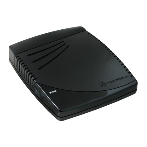
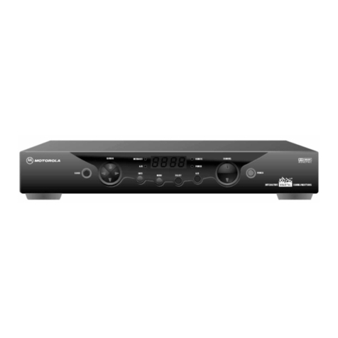
  9. Motorola DCT1700 User manual

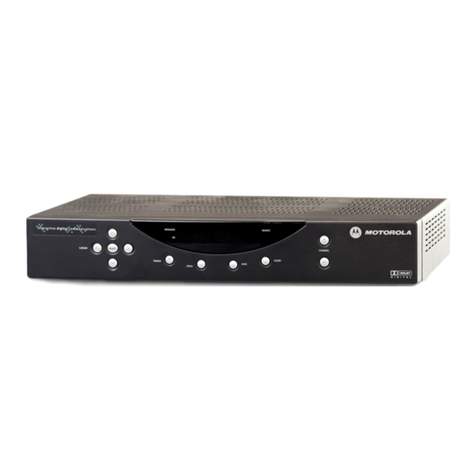
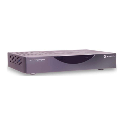
Motorola DCT1700 User manual

Other manuals for DCT1700

1

Other Motorola Touch Terminal manuals

Motorola Malux MTM5400 Series User manual

Motorola

Motorola Malux MTM5400 Series User manual

Motorola VT1000v User manual

Motorola

Motorola VT1000v User manual

Motorola WT4070 Assembly Instructions

Motorola

Motorola WT4070 Assembly Instructions

Motorola QIP2500 Series User manual

Motorola

Motorola QIP2500 Series User manual

Motorola MTP850 Operating and maintenance manual

Motorola

Motorola MTP850 Operating and maintenance manual

Motorola Mts-2000 User manual

Motorola

Motorola Mts-2000 User manual

Motorola VT1000 User manual

Motorola

Motorola VT1000 User manual

Motorola WT4000 - Wearable Terminal - Win CE 5.0 Professional 520... User manual

Motorola

Motorola WT4000 - Wearable Terminal - Win CE 5.0 Professional 520... User manual

Motorola MTP850 User manual

Motorola

Motorola MTP850 User manual

Motorola MTP850 Operating and maintenance manual

Motorola

Motorola MTP850 Operating and maintenance manual

Motorola MK4000 MicroKiosk Installation and operation manual

Motorola

Motorola MK4000 MicroKiosk Installation and operation manual

Motorola MK3000 User manual

Motorola

Motorola MK3000 User manual

Motorola IRRInet-XL User manual

Motorola

Motorola IRRInet-XL User manual

Motorola MC9090 Series Operating instructions

Motorola

Motorola MC9090 Series Operating instructions

Motorola MTP830 Operating and maintenance manual

Motorola

Motorola MTP830 Operating and maintenance manual

Motorola HDT 600 User manual

Motorola

Motorola HDT 600 User manual

Motorola MTP850 Operating and maintenance manual

Motorola

Motorola MTP850 Operating and maintenance manual

Motorola HDT 600 Configuration guide

Motorola

Motorola HDT 600 Configuration guide

Motorola MC3090Z User manual

Motorola

Motorola MC3090Z User manual

Motorola Symbol MicroKiosk MK22 0 Series User manual

Motorola

Motorola Symbol MicroKiosk MK22 0 Series User manual

Motorola TETRA MTH800 User manual

Motorola

Motorola TETRA MTH800 User manual

Motorola MC3190 User manual

Motorola

Motorola MC3190 User manual

Motorola DCT1800 User manual

Motorola

Motorola DCT1800 User manual

Motorola MC909X-K User manual

Motorola

Motorola MC909X-K User manual

Popular Touch Terminal manuals by other brands

Omron NT11S Operation manual

Omron

Omron NT11S Operation manual

Partner SP-820 user manual

Partner

Partner SP-820 user manual

BBPOS WisePad 2 instruction manual

BBPOS

BBPOS WisePad 2 instruction manual

Anywire ASLINKAMP L-A1AW Series Product guide

Anywire

Anywire ASLINKAMP L-A1AW Series Product guide

Festo VIFB4 Series Brief description

Festo

Festo VIFB4 Series Brief description

Linksz CMDA FWT-8828 user manual

Linksz

Linksz CMDA FWT-8828 user manual

Heisei Electronics Q-POS 815 user guide

Heisei Electronics

Heisei Electronics Q-POS 815 user guide

ANUBIS POS50 Series quick guide

ANUBIS

ANUBIS POS50 Series quick guide

Amano MTX-15 installation guide

Amano

Amano MTX-15 installation guide

FLOWBIRD CWT Compact Touch manual

FLOWBIRD

FLOWBIRD CWT Compact Touch manual

Demco SP7 installation guide

Demco

Demco SP7 installation guide

Lathem PC600 Series user guide

Lathem

Lathem PC600 Series user guide

Partner MF-2352 user manual

Partner

Partner MF-2352 user manual

NCR RealPOS 7460-2 supplementary guide

NCR

NCR RealPOS 7460-2 supplementary guide

Simrad MS50 Manual guide

Simrad

Simrad MS50 Manual guide

Unitech MR350 MKII Software guide

Unitech

Unitech MR350 MKII Software guide

Jungheinrich WMT 210 Service manual

Jungheinrich

Jungheinrich WMT 210 Service manual

YASKAWA 62H-MDC0 manual

YASKAWA

YASKAWA 62H-MDC0 manual

manuals.online logo
manuals.online logoBrands
  • About & Mission
  • Contact us
  • Privacy Policy
  • Terms and Conditions

Copyright 2025 Manuals.Online. All Rights Reserved.

InstallationManual
DCT1700
DigitalConsumerTerminal
Graphical symbols and supplement warning marking locations on the bottom of the appliance.
This symbol indicates that dangerous voltage levels are present within the equipment. These voltages are not insulated
and may be of sufficient strength to cause serious bodily injury when touched. The symbol may also appear on
schematics.
This symbol calls attention to a critical procedure, or means refer to the instruction manual for opening or service
information. Only qualified service personnel are to install or service the equipment. The symbol may also appear in text
and on schematics.
WARNING:
TO PREVENT FIRE OR SHOCK HAZARD, DO NOT EXPOSE THIS APPLIANCE TO RAIN OR MOISTURE.
CAUTION:
TO PREVENT ELECTRICAL SHOCK, DO NOT USE THIS PLUG WITH AN EXTENSION CORD, RECEPTACLE, OR OTHER OUTLET
UNLESS THE BLADES CAN BE FULLY INSERTED TO PREVENT BLADE EXPOSURE.
FCC Compliance: Federal Communications Commission Radio and Television Interface Statement for a Class ‘B’ Device
This equipment has been tested and found to comply with the limits for a Class B digital device, pursuant to part 15 of the FCC Rules. These
limits are designed to provide reasonable protection against harmful interference in the residential installation. This equipment generates, uses
and can radiate radio frequency energy and, if not installed and used in accordance with the instructions, may cause harmful interference to radio
communications. However, there is no guarantee that interference will not occur in a particular installation.
If the equipment does cause harmful interference to radio or television reception, which can be determined by turning the equipment off and on,
the user is encouraged to try to correct the interference by one of the following measures:
! Reorient or relocate the receiver antenna
! Increase the separation between the equipment and the affected receiver
! Connect the equipment into an outlet or on a circuit different from that to which the receiver is connected
! Consult the dealer or experienced radio/TV technician for help
! Ensure that the cover plate for the security card is secured and tight
Changes or modification not expressly approved by the party responsible for compliance could void the user’s authority to operate the equipment.
Declaration of Conformity: According to 47 CFR, Parts 2 and 15 for Class B Personal Computers and Peripherals; and/or CPU Boards and
Power Supplies used with Class B Personal Computers, Motorola, Inc., 6450 Sequence Drive, San Diego, CA 92121, 1-800-225-9446, declares
under sole responsibility that the product identifies with 47 CFR Part 2 and 15 of the FCC Rules as a Class B digital device. Each product
marketed is identical to the representative unit tested and founded to be compliant with the standards. Records maintained continue to reflect the
equipment being produced can be expected to be within the variation accepted, due to quantity production and testing on a statistical basis as
required by 47 CFR 2.909. Operation is subject to the following condition: This device must accept any interference received, including
interference that may cause undesired operation. The above named party is responsible for ensuring that the equipment complies with the
standards of 47 CFR, Paragraphs 15.107 to 15.109
Repairs: If repair is necessary, call the Motorola Repair Facility at 1-800-227-0450 for a Return for Service Authorization (RSA) number before
sending the unit. The RSA number must be prominently displayed on all equipment cartons. Pack the unit securely; enclose a note describing the
exact problem, and a copy of the invoice that verifies the warranty status. Ship the unit PRE-PAID to the following address:
Motorola, Inc.
Attn: RSA #___________
c/o Rudolph Miles and Sons
2500 Courage Boulevard
Brownsville, TX 78521
NOTE TO CATV SYSTEM INSTALLER: This reminder is provided to call CATV system installer’s attention to Article 820-40 of the NEC that
provides guidelines for proper grounding and, in particular, specifies that the cable ground shall be connected to the grounding system of the
building, as close as possible to the point of cable entry as practical.
Copyright © 2003 by Motorola, Inc.
All rights reserved. No part of this publication may be reproduced in any form or by any means or used to make any derivative work (such as
translation, transformation or adaptation) without written permission from Motorola, Inc.
Motorola reserves the right to revise this publication and to make changes in content from time to time without obligation on the part of Motorola to
provide notification of such revision or change. Motorola provides this guide without warranty of any kind, either implied or expressed, including,
but not limited to, the implied warranties of merchantability and fitness for a particular purpose. Motorola may make improvements or changes in
the product(s) described in this manual at any time.
STARVUE, STARFONE, MOTOROLA , and the Stylized M Logo are registered in the US Patent & Trademark Office. All other product or service
names are the property of their respective owners.
DCT1700 Installation Manual
Contents
Section 1
Introduction
Using This Manual............................................................................................................................................................................1-2
Related Documentation ...................................................................................................................................................................1-2
Document Conventions ...................................................................................................................................................................1-2
If You Need Help ...............................................................................................................................................................................1-3
Calling for Repairs............................................................................................................................................................................1-3
Section 2
Overview
Front Panel........................................................................................................................................................................................2-1
Rear Panel .........................................................................................................................................................................................2-2
Remote Controls...............................................................................................................................................................................2-3
Motorola Universal Remote Control ......................................................................................................................................2-3
Installing Batteries in Remote Control ..................................................................................................................................2-5
Section 3
Installation
Before You Begin .............................................................................................................................................................................3-1
Installing the DCT1700 .....................................................................................................................................................................3-1
Standard Cabling Diagram ..............................................................................................................................................................3-2
Standard VCR Cabling Diagram......................................................................................................................................................3-3
Composite Baseband Cabling Diagrams .......................................................................................................................................3-4
Stereo Cabling Diagram (Baseband) ..............................................................................................................................................3-6
A/V Receiver Cabling Diagrams......................................................................................................................................................3-8
Operational Check............................................................................................................................................................................3-9
Selecting the OOB Frequency................................................................................................................................................3-9
Cold Initialization............................................................................................................................................................................3-10
ii Contents
DCT1700 Installation Manual
Section 4
Troubleshooting
Appendix A
Specifications
Appendix B
Diagnostics
Accessing Diagnostics....................................................................................................................................................................B-1
Navigating the Diagnostics.............................................................................................................................................................B-2
d 01: General Status ........................................................................................................................................................................B-3
Error Codes..............................................................................................................................................................................B-4
d 02: Out-of-Band (OOB) Status .....................................................................................................................................................B-6
Selecting the OOB Frequency ...............................................................................................................................................B-7
d 03: In-band Status.........................................................................................................................................................................B-8
d 04: Audio/Video Status...............................................................................................................................................................B-10
d 05: Unit Address .........................................................................................................................................................................B-11
d 06: Firmware Version..................................................................................................................................................................B-12
d 07: Current Channel Status .......................................................................................................................................................B-13
Current Channel Variables ...................................................................................................................................................B-15
d 08: Renewable Security System................................................................................................................................................B-16
d 09: Upstream Modem (STARVUE II Diagnostics) ....................................................................................................................B-17
d 10: Application (APP) Code Modules........................................................................................................................................B-18
d 11: Memory Status......................................................................................................................................................................B-19
d 12: Interactive Info ......................................................................................................................................................................B-20
d 13: MAC Frequency Table..........................................................................................................................................................B-21
d 14: Message Types .....................................................................................................................................................................B-22
d 15: In-band Program Association Table (PAT) ........................................................................................................................B-23
d 16: In-band Program Map Table (PMT) .....................................................................................................................................B-23
d 17: Task Status............................................................................................................................................................................B-23
d 18: In-band Multicast Address Filter.........................................................................................................................................B-24
d 19: Keyboard / LED Diagnostics ...............................................................................................................................................B-25
Abbreviations and Acronyms
Contents iii
DCT1700 Installation Manual
Figures
Figure 1-1 DCT1700 advanced set-top ..........................................................................................................................................1-1
Figure 2-1 DCT1700 front panel ......................................................................................................................................................2-1
Figure 2-2 DCT1700 rear panel.......................................................................................................................................................2-2
Figure 2-3 Motorola universal remote control..............................................................................................................................2-3
Figure 2-4 Back view of remote control ........................................................................................................................................2-5
Figure 3-1 Standard cabling ...........................................................................................................................................................3-2
Figure 3-2 Standard VCR cabling...................................................................................................................................................3-3
Figure 3-3 Standard baseband cabling .........................................................................................................................................3-4
Figure 3-4 Composite VCR cabling ...............................................................................................................................................3-5
Figure 3-5 Audio on the VCR..........................................................................................................................................................3-6
Figure 3-6 Audio on VCR/Audio output on TV..............................................................................................................................3-7
Figure 3-7 Audio through A/V Receiver ........................................................................................................................................3-8
Figure B-1 DIAGNOSTICS Main Menu .......................................................................................................................................... B-2
Figure B-2 DCT1700 Status ........................................................................................................................................................... B-3
Figure B-3 OOB Diagnostic ........................................................................................................................................................... B-6
Figure B-4 In-band Diagnostic ...................................................................................................................................................... B-8
Figure B-5 Audio/Video Status.................................................................................................................................................... B-10
Figure B-6 Unit Address .............................................................................................................................................................. B-11
Figure B-7 Firmware Version....................................................................................................................................................... B-12
Figure B-8 Current Channel Status............................................................................................................................................. B-13
Figure B-9 Renewable Security................................................................................................................................................... B-16
Figure B-10 STARVUE II Diagnostic ........................................................................................................................................... B-17
Figure B-11 APP Code Modules.................................................................................................................................................. B-18
Figure B-12 Memory Status......................................................................................................................................................... B-19
Figure B-13 Interactive Info ......................................................................................................................................................... B-20
Figure B-14 MAC Frequency Table............................................................................................................................................. B-21
Figure B-15 Message Types ........................................................................................................................................................ B-22
Figure B-16 In-band PAT.............................................................................................................................................................. B-23
Figure B-17 In-band PMT ............................................................................................................................................................. B-23
Figure B-18 Task Status............................................................................................................................................................... B-23
Figure B-19 In-band Multicast Address Filter............................................................................................................................ B-24
Figure B-20 Keyboard / LED Diagnostics .................................................................................................................................. B-25
iv Contents
DCT1700 Installation Manual
Tables
Table 2-1 Rear panel ....................................................................................................................................................................... 2-2
Table 2-2 Remote control keys ....................................................................................................................................................... 2-4
Table 3-1 Operational check .......................................................................................................................................................... 3-9
Table 4-1 Troubleshooting guidelines .......................................................................................................................................... 4-1
Table B-1 Operational keys using the diagnostics main menu or submenus..........................................................................B-2
Table B-2 Diagnostic Main Menu Fields .......................................................................................................................................B-4
Table B-3 Error codes.....................................................................................................................................................................B-4
Table B-4 OOB Diagnostic Fields..................................................................................................................................................B-6
Table B-5 In-band Diagnostic Fields.............................................................................................................................................B-8
Table B-6 Audio Video Status fields ...........................................................................................................................................B-10
Table B-7 Unit Address Fields ....................................................................................................................................................B-11
Table B-8 Current Channel Status Fields ...................................................................................................................................B-14
Table B-9 Current Channel Status Variables..............................................................................................................................B-15
Table B-10 Renewable Security Fields .......................................................................................................................................B-16
Table B-11 STARVUE II Transmitter Fields ................................................................................................................................B-17
Table B-12 APP Code Modules Fields ........................................................................................................................................B-18
Table B-13 Memory Status Fields................................................................................................................................................B-19
Table B-14 Interactive Info Fields................................................................................................................................................B-20
Table B-15 MAC Frequency Table Fields....................................................................................................................................B-21
Table B-16 Message Types Fields...............................................................................................................................................B-22
Table B-17 In-Band Multicast Address Filter Fields ..................................................................................................................B-24
DCT1700 Installation Manual
Section 1
Introduction
The Motorola DCT1700 is an analog/digital set-top that supports 64 and 256 QAM digital signal
formats. The DCT1700 is compatible with existing Motorola analog and digital set-top products.
The Motorola DCT1700 offers:
! 54 through 860 MHz integrated tuner
! Integrated RF return (using built-in STARVUE II®module)
! RF and baseband audio/ video ports
Figure 1-1 illustrates front and rear views of the DCT1700:
Figure 1-1
DCT1700 advanced set-top
R
RF IN
CABLE IN
TO RF IN
TV Pass Card
AUDIO OUT VIDEO
TO
TV/VCR
L
1-2 Introduction
DCT1700 Installation Manual
Using This Manual
This manual provides instructions to install and configure a DCT1700:
Section 1 Introduction provides a product description, a list of related documentation, the technical
helpline telephone number, and the repair/return procedure.
Section 2 Overview describes the DCT1700 and provides an overview of its use. This section also
identifies the front-panel displays and switches and describes the
rear-panel features.
Section 3 Installation provides instructions on how to install the DCT1700 in a subscriber location
and perform operational tests.
Section 4 Troubleshooting provides guidelines for troubleshooting the equipment.
Appendix A Specifications provide the technical specifications for the DCT1700.
Appendix B Diagnostics provide instructions on accessing and interpreting the built-in diagnostics.
Abbreviations
and Acronyms
The Abbreviations and Acronyms list contains the full spelling of the short forms used in
this manual.
Related Documentation
Separate instruction manuals are available for associated components. Although these may be
useful, they are not necessary to install or operate the DCT1700:
! DCT1700 User Guide
Document Conventions
Before you begin working with this manual and using the DCT1700, familiarize yourself with
the stylistic conventions used in this manual:
SMALL CAPS Denotes silk screening on the equipment, typically representing front- and rear-panel
controls, input/output (I/O) connections, and LEDs
*(asterisk) Indicates that several versions of the same model number exist and the information applies
to all models; when the information applies to a specific model, the complete model number
is given
Italic type Used for emphasis
Courier font Displayed text
Introduction 1-3
DCT1700 Installation Manual
If You Need Help
If you need assistance while working with the DCT1700, contact the Motorola Technical
Response Center (TRC):
! Inside the U.S.: 1-888-944-HELP (1-888-944-4357)
! Outside the U.S.: 215-323-0044
! Online: http://broadband.motorola.com/noflash/websupport.html.
The TRC is open from 8:00 AM to 2:00 AM Eastern Time, Monday through Friday and 10:00 AM
to 5:00 PM Eastern Time, Saturday. When the TRC is closed, emergency service only is
available on a call-back basis. Web Support offers a searchable solutions database, technical
documentation, and low priority issue creation/tracking 24 hours per day, 7 days per week.
Calling for Repairs
If repair is necessary, call the Motorola Repair Facility at 1-800-227-0450 for a Return for
Service Authorization (RSA) number before sending the unit. The RSA number must be
prominently displayed on all equipment cartons. The Repair Facility is open from 8:00 AM to
5:00 PM Central Time, Monday through Friday.
When calling from outside the United States, use the appropriate international access code and
then call 956-541-0600 to contact the Repair Facility.
When shipping equipment for repair, follow these steps:
1 Pack the unit securely.
2 Enclose a note describing the exact problem. Complete and enclose the checklist provided
with the unit.
3 Enclose a copy of the invoice that verifies the warranty status.
Ship the unit PREPAID to the following address:
Motorola, Inc.
Broadband Communications Sector
Attn: RSA #___________
c/o Rudolph Miles and Sons
2500 Courage Boulevard
Brownsville, TX 78521