Mountz SDC-24 User manual

21st Aug, 2017
Operation Manual
Smart Screw Driver SDC-24 / SDC-40
1080 N 11th St - San Jose CA 95112 - mountztorque.com
1

INDEX
1. General safety Rules (English)
7
2. Specific safety Rules (English)
8
3. Product
9
4. Main Feature
9
5. Screwdriver
10
5.1 Specification
10
5.2 Model for SDC-24 Series
10
5.3 Model for SDC-40 Series
11
5.4 Auto Speed Change by Torque Setting
11
5.5 Screwdriver Dimension
12
6. Controller
17
6.1 Specification
17
6.2 Controller Dimension
18
7. Operation
19
7.1 LED Display Details
19
1) Information of LCD
19
2) Key Buttons
19
7.2 Parameter Number Group
21
7.3 Preset Number and Parameters
22
7.4 Torque, Speed & Angle Setting (I) - by PC Program
23
7.5 Torque, Speed & Angle Setting (II) - on the Front Panel
24
7.6 Details of Each Parameter Numbers
25
7.6.1 Fastening Setting
25
1) Torque
P1~8
25
1080 N 11th St - San Jose CA 95112 - mountztorque.com
2

2) Torque Unit
P10
25
3) Rotation Speed (Not Recommended)
P11~18
25
4) Min. Angle Control for Fastening Quality Monitoring
P21~28
26
5) Max Angle Control
P31~38
27
6) Soft Start Setting
P41~48
28
7) Free Speed Setting
P51~58,P84,P102
29
8) Min. Angle Setting on P21~28 and NG type Selecting
P78
29
9) Max Angle Setting on P31~38 and OK/NG Verification
P79
29
10) Output Pin #5 Management (Driver Lock / Angle Count
P86
30
Reset)
11) Auto Speed by Torque Setting
P88
30
7.6.2 Fastening Sequence
30
12) Torque Control Profile Setting
P63~73
30
13) Motor Acceleration
P40
31
7.6.3 Advanced Function
32
14) Free Reverse Rotation Setting
P85, P98, P100,
P101
32
15) Engaging Torque Detection Setting
P103~109
33
16) Auto Reverse Setting
P110~114
35
7.6.4 Controller Setting
36
17) 25P I/O Interface Setting
P20
36
18) FND Display ( for FND version only )
P29
37
19) Auto Fastening Data Output
P30
37
20) Torque Compensation
P39
38
21) Com Port Select
P49
38
22) Initial Loosening Speed
P50
38
23) Converted Torque Limit
P59
39
1080 N 11th St - San Jose CA 95112 - mountztorque.com
3

24) Time Limit for Fastening, Loosening & Motor Stall
P60~62
39
25) Error Display Time Setting
P74
39
26) Beep Sound ON/OFF
P77
40
27) No Torque Complete Error
P89
40
28) Fastening Complete Signal Out Time Setting
P90
40
29) Reverse Lock Setting
P91
40
30) Trigger Start Setting
P92
41
31) Reverse Start Setting
P93
41
32) Bit Socket Tray Program Select
P94
41
33) Baud Rate Setting of RS232C
P97
42
34) Preset # Selecting by Front Panel Key
P115
42
7.6.5 Screw Counter Setting
43
35) Count Start(IN) & Finish(OUT) Signal TypeⅠ
P80
43
36) Count Start(IN) & Finish(OUT) Signal TypeⅡ
P81
43
37) Count Complete Signal Type
P82
44
38) Middle Count Number Setting
P83
45
39) Input Pin #19 Sensor Signal Delay Time Setting
P95
45
40) P82=2 Count Complete Time Setting
P116
45
7.6.6 Model Setting
46
41) Screw Count Number Setting for Each Model
P130~137
46
42)Select Model by 25P I/O Enable/Disable
P138
46
43) Auto Sequence Enable/Disable
P139
47
7.6.7 Driver Setting
47
44) Initial Preset# Display on the Front Panel
P9
47
45)Screw Type (Clockwise & Counter-clockwise)
P19
47
46) Password
P75
47
46) Parameter Initialize to Factory Setting
P76
48
1080 N 11th St - San Jose CA 95112 - mountztorque.com
4

47) Converted Torque Display for Real Time Monitoring
P128
48
48) Error History (Except the Pattern Error)
P200~207
48
49) Torque Tuning
P211~218
49
50) Others
49
7.7 Error code
50
7.8 Preset Number Selecting by Sensor
52
7.9 Wiring Example of Check Out Signal Output
53
7.10 Preset # Selecting by 25P I/O Port
54
7.11 25Pin I/O Port Configuration
54
7.11.1 25Pin I/O Configuration (I) - for Sensor
55
7.11.2 25P I/O configuration (II) - for PLC
56
7.11.3 25P I/O configuration (III) - for Sensor + PLC
57
7.11.4 25P Interface – Input
58
7.11.5 25P Interface - Output
59
7.11.6 Wiring of the Alarm signal to the Tower Lamp
60
7.11.7 Error code pin composition on 25P Output
60
7.12 25PIN I/O Timing Chart
61
7.13 Built in Screw Counter
62
7.13.1 Fastening Quality Verification (OK/NG)
62
1) Fastening OK
62
2) Fastening NG
63
3) Fastening NG - No Torque Up
63
7.13.2 Count Start & Stop Signal to SDC
64
7.13.3 Wiring of Count Start & Stop
68
7.13.4 Operation of Screw Counter on SDC
70
7.13.5 FND Display for Counter Mode
71
7.13.6 FND Display for Model Selecting
71
1080 N 11th St - San Jose CA 95112 - mountztorque.com
5

8. USB Communication
72
8.1 Port and Cable
72
8.2 USB driver Install
72
9. RS-232C Communication
73
9.1 Connection Cable
73
9.2 Protocol
74
9.2.1 Protocol Frame
74
9.2.2 Communication Control Letters
74
9.2.3 Command
74
9.2.4 Check Sum
75
9.2.5 Details of Command
75
9.3 Auto Fastening Data Output
81
10. PC communication Software, Smart-Manager
82
10.1 Software Install
82
10.2 How to Use
82
10.3 Parameter Setting on Smart-Manager
82
1) Fastening Setting
84
2) Profile of Fastening Process
85
3) Advanced Fastening Process
85
4) Counter Setting
86
5) Multi Sequence Setting
86
6) Driver ++ Setting
88
7) Real Time Monitoring Data
88
8) Real time Torque or Angle Curve
89
9) Screw Counter - Single Counter
90
11. Smart-Manager Program Version vs. Controller Firmware Version
91
1080 N 11th St - San Jose CA 95112 - mountztorque.com
6
Smart-Manager Changes History 94

1. GENERAL SAFETY RULES
WARNING! Read and understand all instructions. Failure to follow all instructions listed below, may result
in electric shock, fire and/or serious personal injury
SAVE THIS INSTRUCTIONS
1.1 Work Area
-Keep your work area clean and well lit. Cluttered benches and dark areas invite
accidents.
-Do not operate power tools in explosive atmospheres, such as in the presence of
flammable liquids, gases, or dust. Power tools create sparks which may ignite the dust
or fumes.
-Keep bystanders, children, and visitors away while operating a power tool.
Distractions can cause you to lose control.
1.2 Electrical Safety
-Grounded tools must be plugged into an outlet properly installed and grounded in
accordance with all codes and ordinances. Never remove the grounding prong or
modify the plug in any way. Do not use any plugs. Check with a qualified
electrician if you are in doubt as to whether the outlet is properly grounded. If the
tools should electrically malfunction or break down, grounding provides a low resistance
path to carry electricity away from the user.
-Avoid body contact with grounded surface ad pipes, radiators, ranges and
refrigerators. There is an increased risk of electric shock if your body is grounded.
-Don't expose power tools to rain or wet conditions. Water entering a power tool will
increase the risk of electric shock
-Do not abuse the cord. Never use the cord to carry the tools or pull the plug
from an outlet. Keep cord away from heat, oil, sharp edges or moving parts.
Replace damaged cords immediately. Damaged cords increase the risk of electric
shock.
-When operating a power tool outside, use an outdoor extension cord marked W-A or
W. These cords are rated for outdoor use and reduce the risk of electric shock.
1.3 Personal Safety
-Stay alert, watch what you are doing and use common sense when operating a
power tool. Do not use tool while tired or under the influence of drugs, alcohol, or
medication. A moment of inflation while operating power tools may result in serious
personal injury.
-Dress properly. Do not wear loose clothing or jewelry. Contain long hair. Keep your
hair, clothing, and gloves away from moving parts. Loose clothes, jewelry, or long hair
can be caught in moving parts.
-Avoid accidental starting. Be sure switch is off before plugging in. Carrying tools with
1080 N 11th St - San Jose CA 95112 - mountztorque.com
7

your finger on the switch or plugging in tools may result in personal injury.
-Remove adjusting keys or switches before turning the tool on. A wrench or a key that
is left attached to a rotating part of the tool may result in personal injury.
-Do not overreach. Keep proper footing and balance at all times. Proper footing and
balance enables better control of the tool in unexpected situations.
-Use safety equipment. Always wear eye protection. Dust mask, non-skid safety shoes,
hard hat, or hearing protection must be used for appropriate conditions.
1.4 Tool use and Care
-Use clamps or other practical way to secure and support the workplace to a stable
platform. Holding the work by hand or against your body is unstable and may lead to loss
of control.
-Do not force tool. Use the correct tool for your application. The correct tool will do the
job better and safer at the rate for which it is designed.
-Do not use tool if switch does not turn it on or off. Any tool that cannot be controlled
with the switch is dangerous and must be repaired.
-Disconnect the plug from the power source before making any adjustments,
changing accessories, or storing the tool. Such preventive safety
-Store idle tools out of reach of children and other untrained persons. Tools are
dangerous in the hands of untrained users.
-Maintain tools with care. Keep cutting tools sharp and clean. Properly maintained
tools, with sharp cutting edges are less likely to bind and are easier to control.
-Check for misalignment or binding of moving parts, breakage of parts, and any other
condition that may affect the tools operation. If damaged, have the tool serviced
before using. Many accidents are caused by poorly maintained tools.
-Use only accessories that are recommended by the manufacturer for your model.
Accessories that may be suitable for one tool, may become hazardous when used on
another tool.
1.5 SERVICE
-Tool service must be performed only by qualified personnel. Service or maintenance
performed by unqualified personnel could result in a risk of injury
-When servicing a tool, use only identical replacement parts. Follow instructions in
the Maintenance section of this manual. Use of unauthorized parts or failure to follow
Maintenance instructions may create a risk of electric shock or injury.
2. SPECIFIC SAFETY RULES
2.1 Hold tool by insulated gripping surfaces when performing an operation where the
cutting tool may contact hidden wiring or its own cord. Contact with a "live" wire will
make exposed metal parts of the tool "live" and shock the operator.
2.2 Never lubricate aerosol oil on to the electrical part.
1080 N 11th St - San Jose CA 95112 - mountztorque.com
8

3. Product
It consists of DC Servo screwdriver and controller as a complete system.
1) Standard Item
2) Option Accessories
4. Main Feature
1) Digital torque set and save 8 memories
2) Long endurance, less noise and heat, and light weight screwdriver
3) Auto speed setting by torque setting
4) Monitoring fastening quality and count of screw numbers
5) Error information by code display
6) Easy parameter setting by Smart-Manager (PC software)
7) Real time torque data and curve display
8) Real time fastening data output (USB, RS-232C)
9) Maintenance information and history memory
10) Firmware upgrade by Com port
Screwdriver
Cable_10P (2m)
SDC-24, SDC-40 controller
U-2 Interface converter
USB cable
AC adapter
(DC24V,1A)
Bit socket Tray
1080 N 11th St - San Jose CA 95112 - mountztorque.com
9

5. Screwdriver
5.1 Specification
no
Item
Specification
SDC-24 series
SDC-40 series
1
Output Power
DC24V, 5A max
DC40V, 5A max
2
Motor
Swiss DC servo motor
3
Dimension
Refer 5.2 screwdriver model
4
Torque range
Refer 5.2 screwdriver model
5
Speed range
Refer 5.2 screwdriver model, +/- 5%, Auto change
6
Torque accuracy
10% in full scale
7
Torque repeatability
+/- 3%
8
Bit size
1/4" Hexagonal
9
Start
Remote by I/O, Trigger lever
10
Cable
10P Robot cable
5.2 Model for SDC-24 Series
Type
Torque
Kgf.cm
Speed (RPM)
Auto change
Bit
Automation
Offset
Straight
SD120Z
SDA120
0.30 ~ 1.50
240 -1000
4mm
half moon
SD200Z
SDA200
0.50 ~ 2.00
420 - 1000
SD300Z
SDA300
1.00 ~ 3.00
360 - 890
SDA600
1.50 ~ 6.00
190 - 710
1/4" hex
SDA1000
2.0 ~ 10.0
130 - 430
Manual
SD070
0.10 ~ 0.70
340 - 930
4mm
half moon
SD120
0.3 ~ 1.50
240 - 1000
SD200
0.50 ~ 2.00
420 - 1000
4mm
half moon,
1/4" hex
SD300
1.00 ~ 3.00
360 - 890
SD400
1.50 ~ 4.00
293 - 591
SD600
1.50 ~ 6.00
190 - 710
SD1000
2.0 ~ 10.0
130 - 430
SD1500
3.0 ~ 15.0
120-400
1/4" hex
※Automation type has 4mm bit cushion. / pressure 4 KG
Dia 4mm half moon
or 1/4" Hex
1080 N 11th St - San Jose CA 95112 - mountztorque.com
10

5.3 Model for SDC-40 Series
Type
Torque
Kgf.cm
Speed (RPM)
Auto change
Bit
Automation
Straight
type
SDA05N
1.00 ~ 5.00
400 - 1000
4mm half moon
1/4" hex
SDA09N
1.50 ~ 9.00
300 - 1000
SDA18N
4.0 ~ 18.0
300 - 900
1/4" hex
SDA28N
5.0 ~ 28.0
190 - 780
Manual
SD05N
1.00 ~ 5.00
400 - 1000
4mm half moon
1/4" hex
SD09N
1.50 ~ 9.00
300 - 1000
SD18N
4.0 ~ 18.0
300 - 900
1/4" hex
SD28N
5.0 ~ 28.0
190 - 780
5.4 Auto Speed Change by Torque Setting
SD070
SD120
SD200
SD300
1080 N 11th St - San Jose CA 95112 - mountztorque.com
11

SD400
SD600
SD1000
SD1500
SD18N
SD28N
1080 N 11th St - San Jose CA 95112 - mountztorque.com
12

5.5 Screwdriver Dimension
■Offset Type ( SD120Z, SD200Z, SD300Z )
Ø4.5 Through
Bit : Dia.4 x 44L
1080 N 11th St - San Jose CA 95112 - mountztorque.com
13

■Straight Type ( SDA120-FV, SDA200-FV, SDA300-FV)
1080 N 11th St - San Jose CA 95112 - mountztorque.com
14

■Manual Hand Held Type
Weight
SD070 : 260 gr
SD120 : 260 gr
SD200 : 295 gr
SD300 : 295 gr
SD400 : 380 gr
SD600 : 340 gr
SD1000 : 380 gr
SD070, SD120, SD200, SD300
SD400
SD600
SD1000, SD1500
1080 N 11th St - San Jose CA 95112 - mountztorque.com
15

■Manual Hand Held Type ( SD05N, SD09N, SD18N, SD28N )
1080 N 11th St - San Jose CA 95112 - mountztorque.com
16

6. Controller
6.1 Specification
no
Item
Specification
SDC-24 series
SDC-40 series
1
Rated Input
AC120VC or AC220V, 50~60Hz
2
Rated Output
DC24V, 5A
DC40V, 3A
3
Control
Range
Torque
0.1 ~ 15.0 Kgf.cm
1 ~ 28.0 Kgf.cm
Speed
100 - 1,000 rpm
300 - 1,000 rpm
Angle
0.4° step
4
Preset parameters
Torque, (Speed) & Angle
5
Preset # selecting
1) Front panel button
2) 25P I/O interface
6
Torque calibration
- 10% ~ +10%
7
Auto recognition
Auto detection of connected driver when power ON
of controller
8
Error display
Error code display ( 3 groups )
9
Fastening quality control
Fastening data verification (NG/OK) against the pre-
setting pattern of angle.
10
Screw Counter
Total 8 programs of tightening screw number and
sequence
11
Parameter setting and
monitoring
MS Windows PC software, Smart-Manager
or front panel
12
Operating environment
0 ~ 40℃ / 15 ~ 80% RH ( without dew )
1080 N 11th St - San Jose CA 95112 - mountztorque.com
17

6.2 Controller Dimension
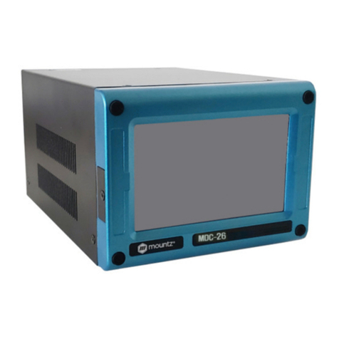
SDC-24
Dimension / Weight
85(w) 210(d) 131.5(h)mm / 1.9 Kg
SDC-40
Dimension / Weight
90(w) 230(d) 141.5(h)mm / 2.3 Kg
1080 N 11th St - San Jose CA 95112 - mountztorque.com
18

7. Operation
7.1 LCD Display Details
1) Information of LCD
2) Key Buttons
button :
By pressing the MODE button, it circulates Auto,
Log-in and Parameter mode. Auto means operating.
Before parameter mode, password required.
Every settings is possible in Parameter mode.
MODE
1080 N 11th St - San Jose CA 95112 - mountztorque.com
19

Button
Log-in Mode
Log-in is required for parameter setting with password.
Initial password "0" can be changed on P75.
Parameter Mode
Cursor shifts up to left at the Parameter mode.
Button
Auto(Work) Mode
Select the next preset number(when P115=1 is enable) or Model
no. select. (when P138=1 is enable)
Log-in & Password
It increases the number up.
Button
Auto Mode (Operation)
It moves the cursor downward.
Parameter Mode
It decreases the number down.
Jog Mode
Manual start / stop in reverse rotation
Enter button
Parameter Mode
It selects or saves the chosen display.
Jog Mode
Manual start / stop in Forward rotation
Button
It returns to the previous mode. Also it resets the error.
RESET
1080 N 11th St - San Jose CA 95112 - mountztorque.com
20
This manual suits for next models
1
Table of contents
Other Mountz Controllers manuals
Popular Controllers manuals by other brands

Extron electronics
Extron electronics MLC Plus 84 EU Setup guide

Honeywell
Honeywell Evohome Applications manual

NXP Semiconductors
NXP Semiconductors MPC5644A Reference manual

REO
REO REOVIB MMFS 268XL 12A operating instructions

Z-Wave.Me
Z-Wave.Me ZME_05459 quick start

Omron
Omron NX Series Network Connection Guide