Advantech-DLoG DLT-V72 Series User manual

www.advantech-dlog.com
Advantech-DLoG
∕DLT-V72 Series
DLT-V72 Series
Industrial PC
Manual V2.00
Manual

IMPORTANT:
Read this manual carefully.
Keep for future reference.
The software and hardware designations as well as the brand names used in this documentation are in most
cases also registered trademarks and are subject to the international law (trademark, brand and patent-protection
laws).
Windows®is a registered trademark of Microsoft Corporation in the United States (US) and other countries.
Intel®and ATOM™ are registered trademarks of Intel Corp.
Android™ is a registered trademark of Google Inc.
Bluetooth®is a registered trademark of Bluetooth SIG, Inc. (Special Interest Group).
RAM®and RAM Mount™ are both trademarks of National Products Inc., 1205 S. Orr Street, Seattle, WA 98108.
Other product names used in this document are for identification purposes only and may be the trademarks of
their respective companies. The DLoG GmbH does not claim any rights to these trademarks.
DLT-V72 devices can be delivered with or without preinstalled software. For devices with preinstalled software
observe the associated license agreements.
FreeRTOS™ is a registered trademark of Real Time Engineers Ltd (http://www.freertos.org).
This product uses FreeRTOS. FreeRTOS is licensed with a modified GNU GPL
http://www.freertos.org/a00114.html.
The FreeRTOS source text is available from http://sourceforge.net/projects/freertos/files/FreeRTOS/V7.4.0/ or
from DLoG GmbH.
We recognize all national and international trademarks and product names.
We reserve the right to modify the contents of this manual at any time and without prior notice.
DLoG GmbH assumes no liability for technical inaccuracies, typographic errors or faults in this documentation.
DLoG GmbH also assumes no liability for damages caused directly or indirectly by the delivery, performance or
usage of this material.
This documentation is protected by copyright. No reproduction, also in excerpts, is permitted without the prior
written permission of the DLoG GmbH.
Manual title: DLT-V72 Industrial PC
Manual completed on: 05/18/2017
Manual PN: 20DLDOCX88520E01
Manual Version: V2.00
Copyright 2016-2017
By DLoG GmbH
All rights reserved
Advantech-DLoG
DLoG GmbH
Industriestraße 15
D-82110 Germering
Phone (+49) 89 / 41 11 91 0
Fax (+49) 89 / 41 11 91 - 900
info@advantech-dlog.com
www.advantech-dlog.com

Table of contents
1. INFORMATION ABOUT THE DLT-V72 MANUALS .................... 5
1.1. Available manuals – in printed form and on the Internet........5
1.2. ONE manual for all device models......................................... 6
1.3. Design elements in the manual..............................................6
2. FUNCTIONAL DESCRIPTION...................................................... 7
2.1. Intended use...........................................................................7
2.1.1. Requirements for safe operation...........................................7
2.1.2. Permitted environmental conditions......................................7
2.2. Mount, operate and service the device correctly....................8
2.3. Warranty conditions................................................................8
2.4. Device identification/name plate.............................................9
3. OPERATION.................................................................................10
3.1. Switching the DLT-V72 on/off.................................................10
3.2. Operating the touchscreen.....................................................11
3.3. DLT-V7210 and DLT-V7212: Front keys and LEDs............... 13
3.3.1. Overview................................................................................13
3.3.2. Keys and LEDsin detail ........................................................13
3.4. DLT-V7210K: Front keys, LEDs and integrated keyboard..... 15
3.4.1. Front keys and LEDs.............................................................15
3.4.2. Integrated keyboard...............................................................17
3.5. Operating states.....................................................................18
3.6. Software keyboard (optional)..................................................19
3.7. Operating the DLT-V72 with UPS...........................................19
4. UNPACKING, TRANSPORT AND STORAGE............................. 20
4.1. Unpacking...............................................................................20
4.2. Transport ................................................................................20
4.3. Storage...................................................................................20
4.3.1. DLT-V72 without UPS...........................................................20
4.3.2. DLT-V72 with UPS (includeslithium-ion batterypack).........20
4.3.3. Protecting touchscreens during storage................................21
4.4. If a return/repacking is necessary...........................................22
5. OPERATING SYSTEMS (OPTIONAL)......................................... 23
5.1. MS-Windows (optional) ..........................................................23
5.1.1. General..................................................................................23
5.1.2. Configuring the front keys, automatic shutdown, etc............24
5.1.3. WES7 and Win 7Prof.: USB icon in the taskbar..................24
5.1.4. Energy options and battery pack durability...........................25
5.1.5. Suppress automaticWindows 10 updates............................25
5.2. Android ...................................................................................26
5.3. Linux (optional).......................................................................26
6. DEVICE CONFIGURATION..........................................................27
6.1. General settings......................................................................27
6.2. Wi-Fi configuration..................................................................28
6.2.1. Safetynotice..........................................................................28
6.2.2. Transmitting power................................................................29
6.2.3. Antenna solutions for use in Germany..................................30
6.2.4. Wi-Fi configuration with LCM or WZC...................................30
6.2.5. Laird Connection Manager (LCM).........................................30
6.2.6. Windows Zero Configuration (WZC).....................................31
6.2.7. Wi-Fi configuration DLT-V72 with ADLoG Android...............31
6.2.8. Wi-Fi configuration DLT-V72 with ADLoG Linux...................31
6.3. Automatic shut down ..............................................................32
6.3.1. Functional description............................................................32
6.3.2. Automaticshutdown configuration.........................................33
7. MECHANICAL INSTALLATION................................................... 34
7.1. Safety notice – observe before installing................................ 34
7.2. Mounting the DLT-V72 at the deployment location................35
7.3. Attaching accessories to the DLT-V72...................................37
7.3.1. VESA mounting hole pattern.................................................37
7.3.2. Attach the ADLoG mounting bracket.....................................38
7.3.3. Attach the ADLoG accessories..............................................39
8. ELECTRICAL INSTALLATION, CABLE CONNECTION,
CABLE COVER ...................................................................................40
8.1. Safety notice – observe before connecting............................40
8.2. Preparations ...........................................................................41
8.2.1. Material required....................................................................41
8.3. Inserting the rubber seal in the cable compartment...............42
8.3.1. Plugging inand screwing on the power supply cable...........43
8.3.2. Securing the ground using ring tongue to the ground bolt....44
8.3.3. Securing the power supply cable to the strain relief rail........45
8.4. Connecting the USB, Ethernet and COM cables....................46
8.4.1. USB cable..............................................................................46
8.4.2. Ethernet cable........................................................................47
8.4.3. COM cable.............................................................................47
8.5. Closing off unused cable openings.........................................48
8.6. Attaching the cable cover .......................................................48
8.6.1. Pressure compensation element...........................................49
9. CONNECTORS.............................................................................50
9.1. Under the cable cover.............................................................50
9.1.1. Network adapter (10/100/1000).............................................51
9.1.2. USB, Service-USB.................................................................51
9.1.3. COM1 and COM2..................................................................51
9.1.4. COM1 as a voltage source....................................................52
9.2. Under the antenna cap...........................................................52
9.2.1. Service USB...........................................................................52
9.2.2. CFast slot...............................................................................53
9.2.3. Antenna cap opening/closing ................................................53
10. INTEGRATED POWER SUPPLY, POWER SUPPLY CABLE..... 54
10.1.1. DC voltage supply connection...............................................55
10.1.2. DC Power supply cable .........................................................56
11. TECHNICAL DATA.......................................................................57
11.1. General...................................................................................57
11.2. Environmental conditions........................................................60
11.2.1. DLT-V72 without integrated UPS..........................................60
11.2.2. DLT-V72 with integrated UPS (optional)...............................60
11.3. Device dimensions..................................................................61
11.3.1. DLT-V7210.............................................................................61
11.3.2. DLT-V7210K..........................................................................62
11.3.3. DLT-V7212.............................................................................63
11.4. Position of VESA drill holes....................................................64
11.4.1. DLT-V7210.............................................................................64
11.4.2. DLT-V7210K..........................................................................65
11.4.3. DLT-V7212.............................................................................66

12. OPTIONAL EQUIPMENT.............................................................. 67
12.1. Integrated UPS (optional).......................................................67
12.1.1. Batterypack specifications....................................................68
12.1.2. Charging the battery pack .....................................................69
12.1.3. Replacing the battery pack....................................................69
12.2. Screen defroster (optional)..................................................... 71
12.3. Integrated low profile Wi-Fi antenna (optional)....................... 72
12.4. External Wi-Fi antenna, remote (optional).............................. 73
12.5. Wi-Fi card (optional)...............................................................74
12.6. Micro Bluetooth adapter (optional) .........................................74
12.7. GPS receiver (optional) ..........................................................75
12.8. Keyboards and keyboard mounts (optional)...........................76
12.9. Scanner and scanner bracket (optional).................................77
12.10. Touch stylus............................................................................78
12.11. USB recovery stick (optional).................................................78
12.12. Protective film for touchscreen (optional)............................... 79
12.13. Screen blanking (optional)......................................................79
13. MAINTENANCE............................................................................80
13.1. Do not repair or modify........................................................... 80
13.2. Replacing the integrated keyboard of the DLT-V7210K......... 80
13.2.1. Remove the integrated keyboard..........................................81
13.2.2. Attach the integrated keyboard .............................................81
13.3. Regular checks and maintenance of the complete system.... 83
13.4. Replacing the battery pack.....................................................83
13.5. Cleaning the DLT-V72............................................................83
14. MALFUNCTIONS AND TROUBLESHOOTING ........................... 85
15. REASONABLY FORESEEABLE MISUSE................................... 87
16. GUIDELINES AND CERTIFICATES............................................. 88
16.1. EC Europe..............................................................................88
16.2. USA/CANADA........................................................................89
16.3. China ......................................................................................90
16.4. Taiwan....................................................................................90
16.5. MIC Japan (previously TELEC)..............................................90
17. END-OF-LIFE DEVICE DISPOSAL..............................................91
18. TECHNICAL CUSTOMER SUPPORT.......................................... 92
19. RETURN SHIPMENT FORM ........................................................ 93
20. LIST OF FIGURES........................................................................ 94

Information about the DLT-V72 manuals
Advantech-DLoG DLT-V72 Series Manual V2.00 5 / 94
1. Information about the DLT-V72 manuals
1.1. Available manuals – in printed form and on the Internet
Contents For target
group Availability
Safety instructions For protecting personnel
and property Skilled
personnel Printed, enclosed with the
device
Quick start guide First steps in installation
and mounting Skilled
personnel
Mounting
instructions for
accessories
Description of mounting
steps Skilled
personnel Printed, enclosed with the
respective accessories
User Manual Complete operating
instructions Skilled
personnel and
trained users PDF files at
www.advantech-dlog.com
Download -> Products
DLoG Config
manual, ADLoG
Linux manual etc.
Description of software
for the DLT-V72 Skilled
personnel
Pay attention to these manuals because they help avoid hazards, reduce repair costs and
downtimes, and increase the reliability and service life of the DLT-V72.
Keep the manuals for future use.
Please contact DLoG GmbH if you require additional information or clarification. You can find the
contact address in section Technical customer support.
Current manual versions at our website
The latest versions of our manuals are available at our website:
www.advantech-dlog.com -> Download -> Products
Observe safety notices
Observe the "DLT-V72 Safety Instructions" included with the device.

Information about the DLT-V72 manuals
6 / 94 DLT-V72 Series Manual V2.00 Advantech-DLoG
1.2. ONE manual for all device models
This manual applies to all models of the DLT-V72 series. Differences with regard to operation,
functionality, etc. are clearly indicated in the manual.
−DLT-V7210 with 10" display
−DLT-V7210K with integrated keyboard
−DLT-V7212 with 12" display
−Device model with resistive touchscreen
−Device model with projected-capacitive touchscreen (PCT)
−And more
1.3. Design elements in the manual
The following design elements are used in this manual:
DANGER / WARNING / CAUTION
DANGER means that death or severe bodily injury will occur if this information is not observed.
WARNING means that death or severe bodily injury can occur if this information is not
observed.
CAUTION
means that slight bodily injury can occur if this information is not observed.
NOTICE: Physical damage
Information about possible physical damage
TIP / HINT
Tips, hints for using the product
Note about additional information in manuals

Functional description
Advantech-DLoG DLT-V72 Series Manual V2.00 7 / 94
2. Functional description
2.1. Intended use
Fig. 2.1: DLT-V72 device examples with optional mounting bracket
The DLT-V72 industrial PCs are data
communication terminals for use in commercial
environments (e.g. logistics, warehousing,
manufacturing). Any other or additional use
beyond this shall be deemed an improper use.
The user/operator of the DLT-V72 is solely
responsible for any resulting damage. This also
applies to any unauthorized modifications made
to the device.
Intended use includes the compliance with the environmental conditions permitted for the device (e.g.
ambient temperature -30 °C to +50 °C) and specifications (e.g. DC power supply unit 12/24/48 VDC) as
well as compliance with all safety Instructions.
The DLT-V72 industrial PCs:
−are not approved for use in EX zones (potential explosion hazard).
−are not approved for use on ships.
−are not approved for use on rail vehicles
−are not approved for use in life-support systems or critical safety systems where system
malfunction can lead to the direct or indirect endangerment of human life.
Only use accessories that have been tested and approved by Advantech-DLoG for the respective DLT-
V72. Otherwise, any DLoG GmbH warranty for this device will be void.
2.1.1. Requirements for safe operation
The requirements are:
−Proper transport and storage.
−Proper setup and use.
−Proper maintenance and service.
−Operation by trained personnel.
2.1.2. Permitted environmental conditions
DLT-V72 industrial PCs may only be used under specified environmental conditions.
See section 11.2 Environmental conditions.

Functional description
8 / 94 DLT-V72 Series Manual V2.00 Advantech-DLoG
2.2. Mount, operate and service the device correctly
DLT-V72 industrial PCs were designed and built according to modern technology and accepted safety
regulations. However, the operation of the DLT-V72 can endanger personnel or third parties and cause
damage to the device and other material assets when, for example, the device is
−installed incorrectly or configured improperly.
−operated by untrained or uninstructed personnel.
−improperly operated and maintained.
−not used as intended.
The owner/operator commitments with regards to safety (accident prevention regulations, occupational
safety) are to be followed.
2.3. Warranty conditions
For DLT-V72 industrial PCs, batteries and accessories the Advantech-DLoG TOB regulations are valid
(section Liability for defects -> limitation period for claims).
Find details on the Advantech-DLoG Internet homepage www.advantech-dlog.com.
LCD display
The LCD display of the DLT-V72 series fulfills the highest quality standards and was inspected for pixel
defects. However, due to technological reasons pixel defects can occur.
This is not a malfunction; it is a part of the technical specifications.

Functional description
Advantech-DLoG DLT-V72 Series Manual V2.00 9 / 94
2.4. Device identification/name plate
The name plate is located on the rear side of the DLT-V72. It must remain legible at all times for
purposes of identifying the device.
Do not damage the name plate or remove it from the device.
Information about the name plate:
Information Explanation
DLoG GmbH Manufacturer contact information
Model DLT-V7210
DLT-V7212 Device name; the last two characters of the name indicate the
display size 10.4", 12.1".
Front D: Screen defroster
R: Resistive touchscreen
P: PCT
K: Integrated keyboard
9-digit ID Identification code (characters from left to right)
Input V / A Input voltage of DC power supply unit nominal current
S/N .... Serial number: Specific Advantech-DLoG device code
Mfd Week and year of manufacture
Barcode For Advantech-DLoG internal purposes
Comment: X stands for not present / not applicable respectively as placeholder for add-ons.

Operation
10 / 94 DLT-V72 Series Manual V2.00 Advantech-DLoG
3. Operation
3.1. Switching the DLT-V72 on/off
The following factors determine how the DLT-V72 can be switched on and off:
−Is the DLT-V72 mounted on a vehicle and connected with the ignition signal?
−What are the automatic shutdown settings that were defined in the DLoG Config configuration
program?
Switch on
Switch the DLT-V72 on as follows, depending on the configuration:
Press the <Power> button.
Or: By applying the supply voltage.
Or: Through the ignition signal of the vehicle (depends on automatic shutdown settings).
Fig. 3.1: <Power> button of the DLT-V72

Operation
Advantech-DLoG DLT-V72 Series Manual V2.00 11 / 94
Switch off
Switch the DLT-V72 off as follows, depending on the configuration:
Press the <Power> button of the activated DLT-V72.
Or: Disconnect the supply voltage.
NOTICE:
Devices without integrated UPS will be hard-terminated (data loss possible).
Devices with integrated UPS will switch automatically to UPS/battery power supply when the supply
voltage is broken.
Or: Deactivate the ignition of the connected vehicle (depends on automatic shutdown settings).
WARNING
Electric shock due to incomplete switching off of the DLT-V72 with integrated UPS.
Because of the lithium-ion battery pack, the integrated UPS may still carry current even if the
DLT-V72 itself is switched off.
Reason: If the DLT-V72 has been configured to also start without <Power> button and ignition in
the "DLoG Config" program, this setting will need to be changed first. Otherwise, the DLT-V72
will restart after a short pause as long as there is available battery capacity.
Shut down the DLT-V72 via the operating system function.
Disconnect from the power supply.
Open the battery cover; unplug the battery pack.
Time between switching off and on: 10 seconds
After the DLT-V72 has been shut down and switched off, it takes 10 seconds until the device will react to
a switch-on signal (<Power> button / ignition).
3.2. Operating the touchscreen
Depending on the equipment, the DLT-V72 will have:
−A resistive touchscreen
−or a projected-capacitive touchscreen with glass front ( PCT).
NOTICE: Physical damage
Improper operation can cause damage and downtimes to the DLT-V72 and to the
connected complete system.
Operators of the DLT-V72 must be trained in the handling of the device.

Operation
12 / 94 DLT-V72 Series Manual V2.00 Advantech-DLoG
Operating the touchscreen
All touchscreens can be operated with:
−Clean, dry fingers.
−Clean, dry, soft gloves.
Resistive touchscreens with:
−Suitable touch stylus (plastic or wood, rounded tip)
PCT touchscreens with:
−Suitable touch stylus with capacitive (electrically conductive) tip.
Prevent damage to the touchscreen
Valid for all touchscreen versions: Resistive and PCT!
Keep the touchscreen clean.
Do not touch the touchscreen with pointed, sharp, rough or hard objects, e.g. ball point pens, writing
implements, tools of any kind (e.g. screwdrivers).
Make sure that no adhesives get on the surface of the touchscreen.
Ensure that the screen surface is not influenced by high voltages or static electricity.
Do not use excessive force when touching touchscreens, do not hit or press hard.
If the device with the touchscreen is placed down: Place a clean, soft cloth underneath.
NOTICE: Physical damage
Salt water on the PCT touchscreen can be interpreted as a "touch" and lead to malfunctions.
Multi-touch capability
Depending on the installed operating system type, the PCT touchscreen of the DLT-V72 is multi-touch
capable. This means it can detect two touches simultaneously.

Operation
Advantech-DLoG DLT-V72 Series Manual V2.00 13 / 94
3.3. DLT-V7210 and DLT-V7212: Front keys and LEDs
3.3.1. Overview
Fig. 3.2: Operating elements DLT-V7210 and DLT-V7212:
3.3.2. Keys and LEDs in detail
Left on DLT-V7210 and DLT-V7212:
Key Explanation
<Power> button, switch device on/off
Manual brightness control: Display brighter
Manual brightness control: Display darker
Switch the backlight on/off
NOTE: The DLT-V72 will continue to react to keyboard, mouse and
touchscreen inputs even if the backlight is switched off. This means that
entries can still be made even when the screen display is not visible.
Function 1: Activate/deactivate touchscreen
Touch LED on (orange): Touchscreen inactive
Touch LED off: Touchscreen active
Function 2, in combination with the <SHIFT> key:
Activate/deactivate screen defroster (optional)
NOTE: The temp LED indicates whether the screen defroster is active or
inactive, not the touch LED above this key.
Keys left side:
- Device on/off
- Display brighter
- Display darker
- Backlighting on/off
- Touch or Screen-
Defroster on/off
Keys right side:
- Special keys
S1 up to S8
- SHIFT-key

Operation
14 / 94 DLT-V72 Series Manual V2.00 Advantech-DLoG
LED Explanation
Function 1: Display of excessive or insufficient temperature in the
device
Temp LED flashes red
Function 2: Display of screen defroster active or inactive
Temp LED on (red): Screen defroster is active
Temp LED off: Screen defroster is inactive
LED on (green): Indicates access to the flash drive
LED on (green): Display of available internal supply voltage
Right on the device:
Key Explanation
Special keys <S1> to <S8>
These keys are configured with the "DLoG Config" program;
the associated manual is available in the Download Center at
www.advantech-dlog.com.
<SHIFT> key
If the LED is illuminated, it indicates that <SHIFT> is activated.

Operation
Advantech-DLoG DLT-V72 Series Manual V2.00 15 / 94
3.4. DLT-V7210K: Front keys, LEDs and integrated keyboard
Fig. 3.3: DLT-V7210K Front keys, LEDs and integrated keyboard
3.4.1. Front keys and LEDs
Left on DLT-V7210K:
Key Function when FN key not activated
(FN LED is off) Function when FN key is activated
(FN LED is on)
Power button, switch device on/off
Display brightness control:
Display brighter / darker
Integrated keyboard brightness control:
Background of keyboard brighter /
darker
Background lightning of the display on / off.
NOTE: The DLT-V7210K will continue to react to
keyboard, mouse and touchscreen inputs even if the
backlight is switched off.
Background lightning of the integrated
keyboard on / off
Activate/deactivate touchscreen.
Touch LED on (orange): Touchscreen inactive
Touch LED off: Touchscreen active
No function
With FN key pressed (LED on):
The special keys to the right on the device are shifted to assignment S2 to S12 (permanent, until
FN is pressed again).
The brightness/illumination keys to the left on the device affect the integrated keyboard, not the
display (permanent, until FN is pressed again).
The alternative characters of the individual keys shown in red are activated on the integrated
keyboard (not permanent).
Keys left side:
- Device on/off
- Display brighter
- Display darker
- Backlighting on/off
- Touch on/off
- FN: Switch special
keys S1 up to S6 to
assignment
S2 up to S12
Keys left side:
- Special keys
S1 up to S12
Bottom: Integrated keyboard

Operation
16 / 94 DLT-V72 Series Manual V2.00 Advantech-DLoG
Right on DLT-V7210K:
Key Explanation
Up to
Special keys S1 up to S12
For customer-specific configuration.
Configure with „DLoG Config“, „ADLoG Linux“ or „ADLoG Android“ (depends on OS).
LEDs
LED
Explanation LED on: Display of
available internal supply
voltage
Display of excessive or
insufficient temperature in
the device; Temp LED
flashes red
LED on: Indicates access to the
flash drive

Operation
Advantech-DLoG DLT-V72 Series Manual V2.00 17 / 94
3.4.2. Integrated keyboard
The integrated keyboard of the DLT-V7210K is available in three languages: German, English and
French.
Example English version (QWERTY)
Description of specific keys
Key Function
<Shift> key
Caps Lock: permanent switch to uppercase letters
Activate the FN key on the left of the device: See the explanation there.
Windows key

Operation
18 / 94 DLT-V72 Series Manual V2.00 Advantech-DLoG
3.5. Operating states
Status of LEDs
DLT-V72 status
Supply voltage
Temperature
OFF OFF Initial state, idle time – waiting for a new
ignition signal or for the <Power> key after
switch-off; no voltage supply
OFF FLASHING Temperature sensor faulty
FLASHING OFF DLT-V72 is in standby mode (S3)
OFF ON Computer will only start if the temperature in
the device is in the range between -30 and
+59 °C again.
ON OFF Computer start-up/normal operational
state/shutdown delay time
ON ON Screen defroster active
ON FLASHING Ambient temperature lies outside of the
permitted range, i.e. < -30 or > +50 °C

Operation
Advantech-DLoG DLT-V72 Series Manual V2.00 19 / 94
3.6. Software keyboard (optional)
The optional DLoG software keyboard brings the complete standard keyboard with function keys and
numeric pad directly to your DLT-V72 screen – with easy touch operation.
Any entries made, for example, letters and numbers, are passed to the currently active application
program.
Example for a software keyboard (the layout can be configured individually):
Fig. 3.4: Software keyboard
If the software keyboard was ordered together with the DLT-V72 industrial PC, then the program will
have been fully pre-licensed by the Advantech-DLoG production department. For subsequent
installation, an installation program is available.
The manual for the DLoG software keyboard is available in the Download Center
at www.advantech-dlog.com.
3.7. Operating the DLT-V72 with UPS
WARNING
Personal injury due to short-circuit, fire, chemical burns, toxic substances.
DLT-V72 devices with integrated UPS contain lithium-ion battery packs. These can ignite if
handled or stored improperly (risk of fire), cause chemical burns or release toxic substances.
Use care when handling lithium-ion battery packs.
Do not damage lithium-ion battery packs; do not drill through and do not crush or drop.
Do not allow water or other liquids to come into contact with the device (exercise particular
caution with corrosive liquids).
Do not allow it to come into contact with fire.
For details about the UPS, see section 12.1 Integrated UPS (optional).

Unpacking, transport and storage
20 / 94 DLT-V72 Series Manual V2.00 Advantech-DLoG
4. Unpacking, transport and storage
4.1. Unpacking
Open the packaging carefully to prevent damaging the device inside.
Save the packaging material (for possible forwarding transports or returns of the DLT-V72).
Check the shipment for completeness and any possible damage.
Always keep the supplied manuals and documents.
4.2. Transport
WARNUNG
Risk of injury due to weight and sharp-edged parts.
The DLT-V72 can fall down and cause injuries due to its weight.
The strain relief rail can have sharp edges and cause cutting injuries.
Always hold the DLT-V72 by the housing with both hands.
Never use the antenna cap as a handle. It can break due to the weight involved.
Do not hold the DLT-V72 by the strain relief rail.
Use the assistance of a second person for installation work.
4.3. Storage
4.3.1. DLT-V72 without UPS
Observe the permissible storage temperature range in the manual, section
11.2 Environmental conditions.
4.3.2. DLT-V72 with UPS (includes lithium-ion battery pack)
Observe the permissible storage temperature range in the manual, section
12.1.1 Battery pack specifications.
Observe the intended use of the DLT-V72, e.g.: no use in EX zone (potentially explosive), no
use in life-supporting systems or security-critical facilities.
For details, see manual, section 2.1 Intended use .
Other manuals for DLT-V72 Series
5
This manual suits for next models
5
Table of contents
Other Advantech-DLoG Industrial PC manuals

Advantech-DLoG
Advantech-DLoG DLT-V4108 User manual
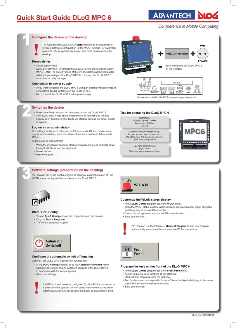
Advantech-DLoG
Advantech-DLoG MPC 6 User manual
Advantech-DLoG
Advantech-DLoG DLT-V8310 User manual
Advantech-DLoG
Advantech-DLoG DLT-V83 Series User manual
Advantech-DLoG
Advantech-DLoG DLT-V6210 User manual
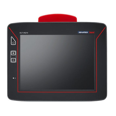
Advantech-DLoG
Advantech-DLoG DLT-V6210 User manual
Advantech-DLoG
Advantech-DLoG DLT-V6210FL User manual

Advantech-DLoG
Advantech-DLoG DLT-V6210FL User manual

Advantech-DLoG
Advantech-DLoG MTC 6 Series User manual
Advantech-DLoG
Advantech-DLoG DLTV72INT User manual
