Movex Track-O CROSS-COUNTRY UTILITY User manual

Track-O
«CROSS-COUNTRY
UTILITY»
OPERATING MANUAL
READ CAREFULLY THIS
MANUAL BEFORE USING
THE TRACK-O
GENERAL SAFETY AND USE OF A TRACK-O
OPERATOR TRAINING REQUIRED
The employer must ensure that each operator of the TRACK-O has the skills to use
it safely, after receiving full training and assessment by a qualified person.
It is the employer’s responsibility to ensure that each operator has successfully
completed the required training.
Any user of a Track-O must know and master the basic principles of safety and use
of this device before using it.
GENERAL SAFETY RULES
Check the general condition of the Track-O, and if you see any anomaly, do share
them with your technical representative or anyone who can provide you technical
support (supplier or manufacturer).
The Track-o is very stable and highly reliable, please do not take any unnecessary
risk when operating this device.
Any reckless operation should be prohibited.

PRECAUTIONS BEFORE USE:
Make sure the route to take is free from objects and surfaces that are free from
grease and/or lubricants which may result in a reduced friction tracks. Also,
please make sure that the route to take do not require special protection if
restricted area.
Ensure that borrowing passages support the total load to be moved.
Never leave the unit where harmful.
The Track-O must not to be set in motion while the cable for recharging the
battery is still plugged in.
Ban all uses of the Track-O in an atmosphere containing a hazardous concentration
of acetylene, butadiene, ethylene oxide, hydrogen (or hazardous gases such as
manufactured gas), propylene oxide, of acetaldehyde, cyclopropane, diethyl
ether, ethylene, isoprene or unsymmetrical dimethylhydrazine (UDMH)
Ban all uses of the Track-o in a room where the atmosphere contains a harmful
concentration of metal dust including aluminum, magnesium and their commercial
alloys, other metals with similar hazardous properties, or in a room which
atmosphere contains carbon black, coal or coke dust.
The Track-O will function in temperatures between -25°C and + 40°C ( -13°F and
+ 104°F )
In case of failure or doubt concerning the use of the Track-O, please contact your
supplier. Do not take any risk to avoid any severe or fatal injury.
Never use the Track-O in water. It is not amphibious.
As part of the use of several Track-O at once in one place, operators must hold
approximately three lengths margin of safety equipment, and especially extra
careful in checking their gear perfectly.

BEFORE EACH HANDLING OPERATION WITH A TRACK-O:
Ensure that the load being moved is within the limits of weight recommended by
the manufacturer, depending on the model used, and this, as well as on flat
surface as inclined surface.
Ensure that the load is securely attached through the anchor eyelet.
Make sure the path does not have a bank angle greater than 15 degrees, and a
pitch or steeper than 40 degrees.
Never hesitate to do a dry run in order to best anticipate the space available to
maneuver.
DURING EACH HANDLING OPERATION WITH A TRACK-O:
Never use both remotes (wired and wireless) at the same time. One is enough and
may prefer the wireless remote (optional) for convenience.
Never stand downstream (below) the Track-O, but either side for wired remote
safe convoy, or outright upstream (above) of the convoy through the wireless
remote. This applies to both the operator and others in attendance in the scope of
the maneuver.
Never place hands near the track as the switch is turned OFF and the unit is not
completely still.
In all case, never stand below the Track-o and its load. If the load was to fall you
could be severely or mortally injured.
Before engaging the unit in an inclined, double check if the straps and anchor
points are in good condition and the unit responds well to the remote on the flat
surface.

AFTER EACH HANDLING OPERATION WITH A TRACK-O:
At the end of each use, power off the Track-O by pushing the emergency button on
the electrical panel. If you have a wireless remote, power off the remote by
pressing the emergency button on remote. Also, turn off the emergency stop on
the control panel.
Remember to keep the remote in the compartment.
Check the charge level of the Track-O, and if necessary, put in charge for the next
use.

TABLE OF CONTENTS
GETTING STARTED / CROSS-COUNTRY UTILITY
Putting breaker to “ON” position.................................... 7-8
Control panel.............................................................. 9
Wireless remote control ................................................. 9
Wired remote control................................................... 10
Moving the Track-O ..................................................... 11
Inclinometers ............................................................ 11
Working angles........................................................... 12
Configuration of the Track-O box ..................................... 13
Securing the transformer............................................... 14
Positioning the capstan................................................. 15
Retention mechanism................................................... 16
Installation to the pole ................................................. 16
Connecting the capstan to the Track-O .............................. 17
FEATURES ................................................................ 18-19
FOR SAFETY REASONS, BEFORE OPERATING THE TRACK-O, PLEASE
FAMILIARIZE YOURSELF WITH THE PRODUCT AND BE SURE TO
THOROUGHLY READ THE INSTRUCTIONS AND PRECAUTIONS CONTAINED
IN THIS MANUAL
OPERATING MANUAL
Page 7 of 19
GETTING STARTED / CROSS-COUNTRY UTILITY
IMPORTANT
PUTTING BREAKER TO «ON» POSITION
DUE TO SHIPPING REGULATIONS, CIRCUIT BREAKERS ARE IN OFF
POSITION
BEFORE OPERATING THE TRACK-O, FOLLOW
INSTRUCTIONS BELOW
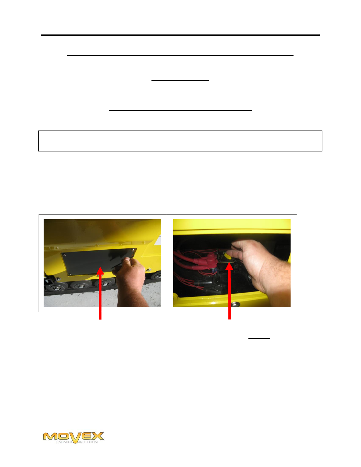
1) REMOVE THE ACCESS PANEL LOCATED ON THE LEFT SIDE OF THE
TRACK-O AND TURN YELLOW BREAKER SWITCH TO «ON» POSITION.

OPERATING MANUAL
Page 8 of 19
2) REPLACE THE ACCESS PANEL
3) UNSCREW THE SCREWS AND NUTS ON EACH SIDE OF THE BOX. TAKE
CARE TO REMOVE ONLY SCREWS AND NUTS AT THE TOP OF THE BOX.
4) TIP UP THE INNER PLATE AND TURN YELLOW BREAKER SWITCH TO
«ON» POSITION.
5) REPOSITION THE INNER PLATE AND TIGHTEN THE SCREWS AND NUTS.
OPERATING MANUAL
Page 9 of 19
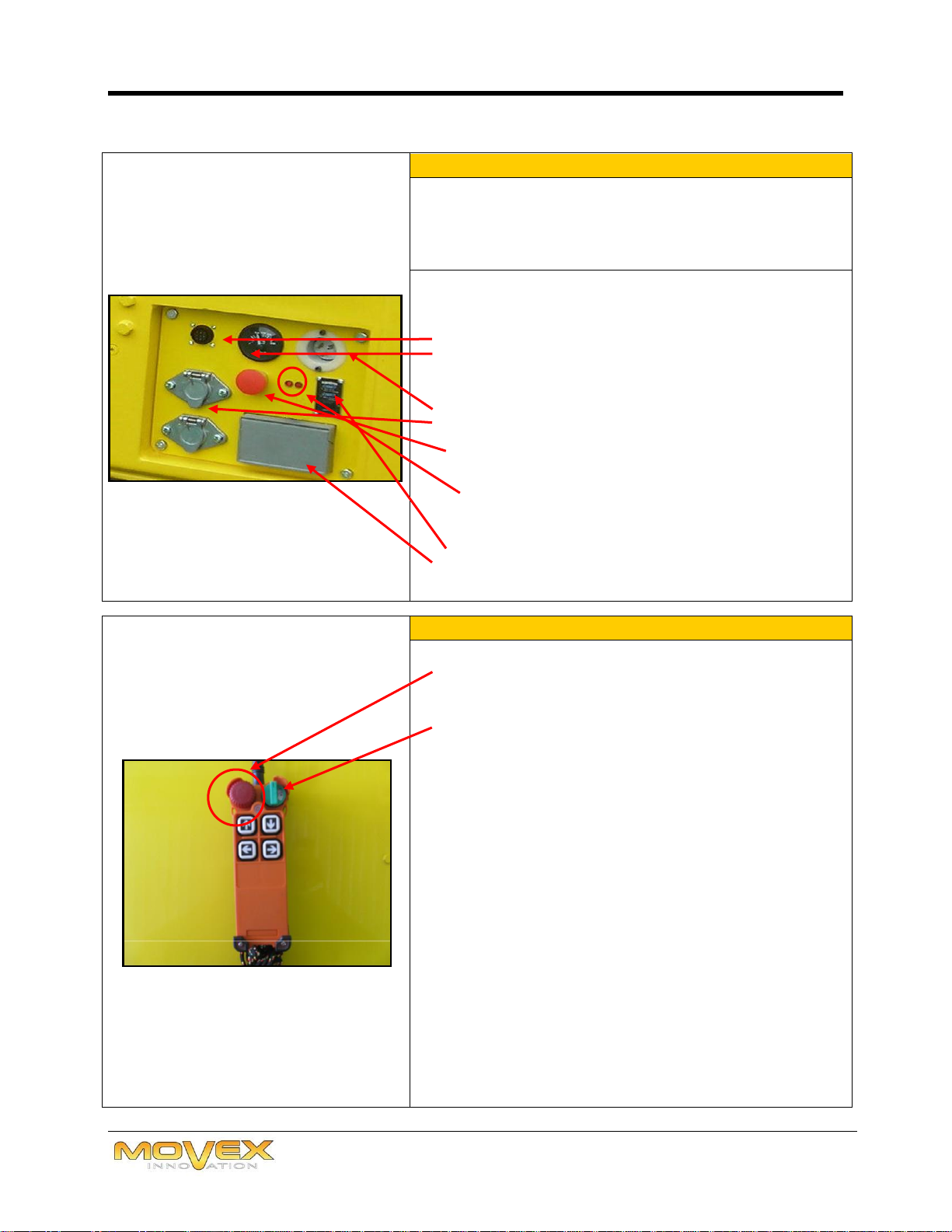
1 CONTROL PANEL
Note: Recharge when the needle shows 23 V.
A - Cable connector for the Track-O’s wired control
B - Voltmeter battery power display
Empty battery 22V
Full battery: between 24 and 28V
C - Charging socket
D - 24V outlet
E - Emergency stop.
F- Light signal indicating Track-O status
2 lights on = ok
Blinking light = problem (see wireless control) >
If the light flashes on the control panel of the
Track-O, it has to be reset.
G- Switch for the 120v inverter
H- 120V outlet
2 WIRELESS REMOTE CONTROL
The red emergency stop button on the remote
control should not be pressed.
Turn the green ignition key to activate the
remote green light.
The green light indicates that the wireless
connection has been established.
The red light indicates that the wireless connection
has not been established
The remote is powered by two AA batteries.
Note: Signal range can reach up to approximately
30 feet and self-deactivates after 10 minutes of
inactivity.
A
C
D
E
G
H
CAUTION:
The red emergency stop
button should not be
pressed!
F
B
OPERATING MANUAL
Page 10 of 19
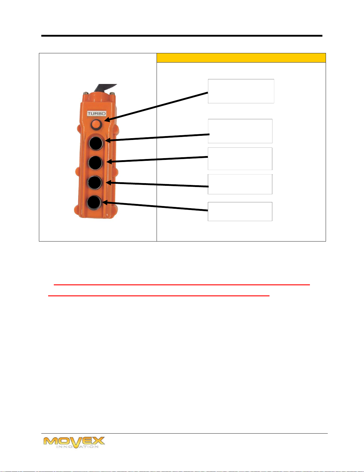
3 WIRED REMOTE CONTROL
FOR SAFETY REASONS IT IS STRONGLY RECOMMENDED THAT
WHEN THE TRACK-O IS NOT BEING USED TO MOVE A LOAD
THAT THE EMERGENCY STOP BUTTON BE PRESSED (EITHER ON
THE TRACK-O OR ON THE WIRELESS REMOTE CONTROL OR BOTH).
THIS WILL AVOID AN UNWANTED AND DANGEROUS MOVEMENT
OF THE TRACK-O CAUSED BY AN ACCIDENTAL PRESSING OF A
BUTTON ON THE WIRELESS REMOTE CONTROL.
FORWARD
REVERSE
TURN RIGHT
TURN LEFT
ACTIVATION
OF 2nd SPEED
OPERATING MANUAL
Page 11 of 19
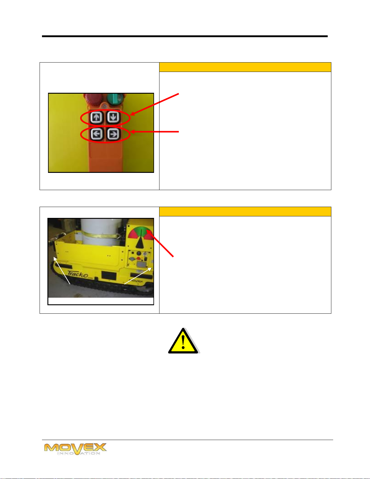
4 MOVING THE TRACK-O
By pressing gently the “Forward”or “Back”
buttons, you can move the Track-O slowly:
putting more pressure on the buttons will make
the Track-O accelerate the movement.
The direction buttons allow left or right
movements of the Track-O. Light pressure allows
for a simple curve, increased pressure for a
tighter curve.
Simultaneous pressure of both “Forward” and
“Back” buttons and direction button will create a
wide curve in the desired direction.
5 INCLINOMETERS
The degrees of tilt during movements are
represented by the Track-O’s integrated
inclinometers.
The green area indicates the comfort zone.
The red areas indicate a no-work zone.
Maximum longitudinal tilt: 40°
Maximum lateral tilt: 15°
WARNING
FRONT
BACK
Always put Front-end on the elevated part of an inclined
surface.
OPERATING MANUAL
Page 12 of 19
6 WORKING ANGLES
When the Track-O is used on rough terrain or
covered with vegetation, safety skates should
be installed.
The skates are kept in the storage
compartment.
These pads fit into the side cavity of the cab to
ensure the stability of the Track-O in case of
unexpected side tilt due to uneven terrain.
The skates can be removed to clear obstacles
such as stumps. However, this manoeuvre can
be performed only when the Track-O is
perfectly stable. The skates should be
reinstalled after obstacles are cleared.
Note: The skates have a print: they are
associated with the specific side (Right and
Left).
OPERATING MANUAL
Page 13 of 19
7 CONFIGURATION OF THE TRACK-O BOX
The Track-O box can be configured to carry
securely several types of transformers.
The sides can be removed if needed to allow the
cooling radiators to be loaded on the Track-O
box.
OPERATING MANUAL
Page 14 of 19
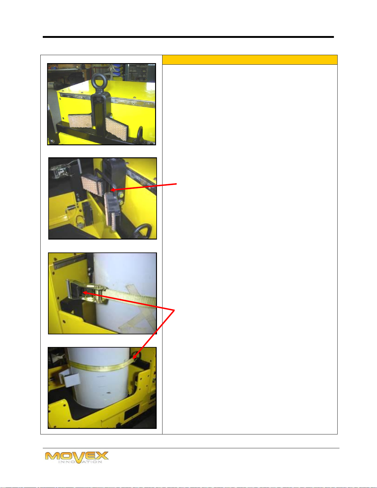
8 SECURING THE TRANSFORMER
Securely place the transformer against the
support.
Ensure that the adapter is required to properly
shoulder the transformer to the support. The
adapter is set on the existing support to allow a
better clearance for certain types of transformer.
Note: This adapter is generally used for
very old transformers.
Secure the transformer using with the ratchet
belt tensioners provided for this use.

OPERATING MANUAL
Page 15 of 19
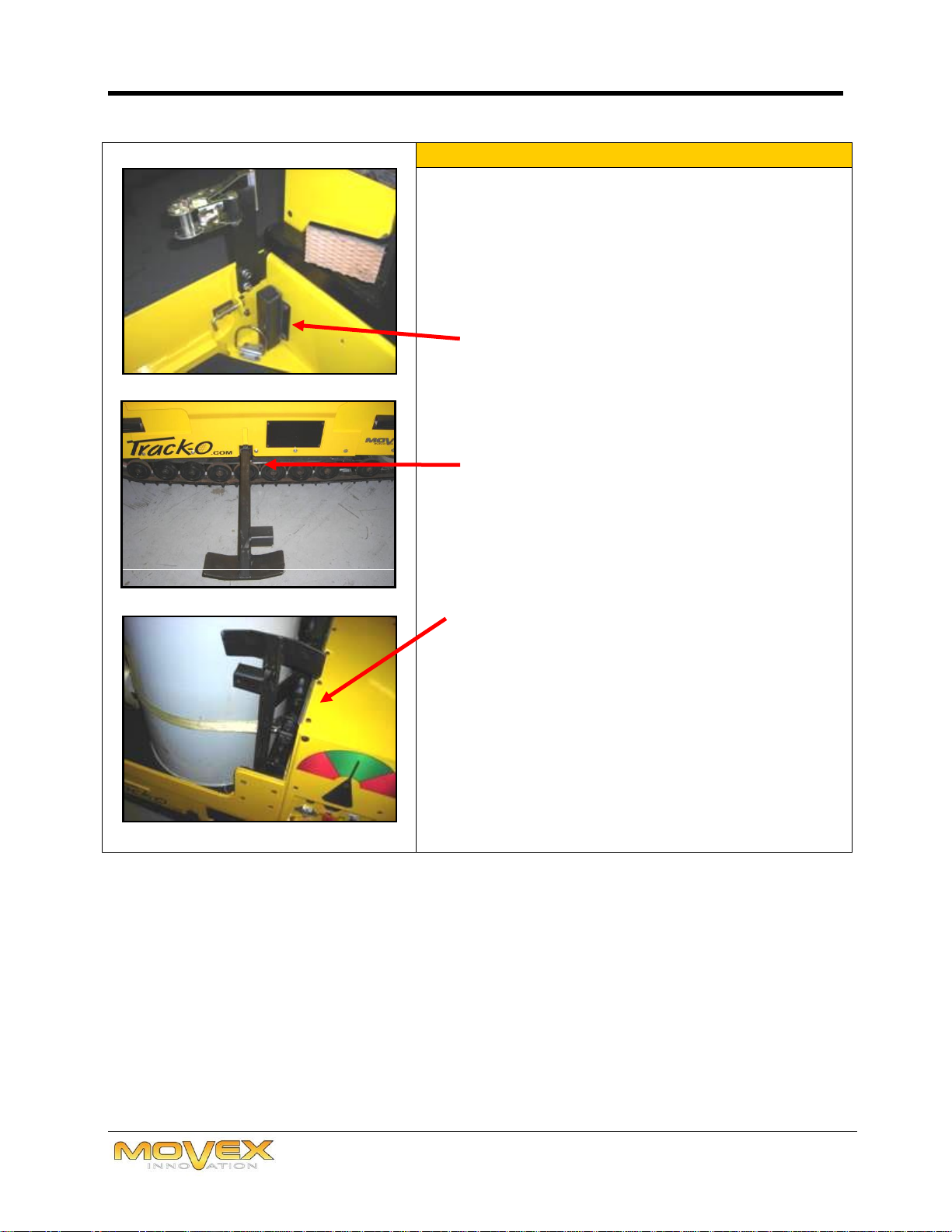
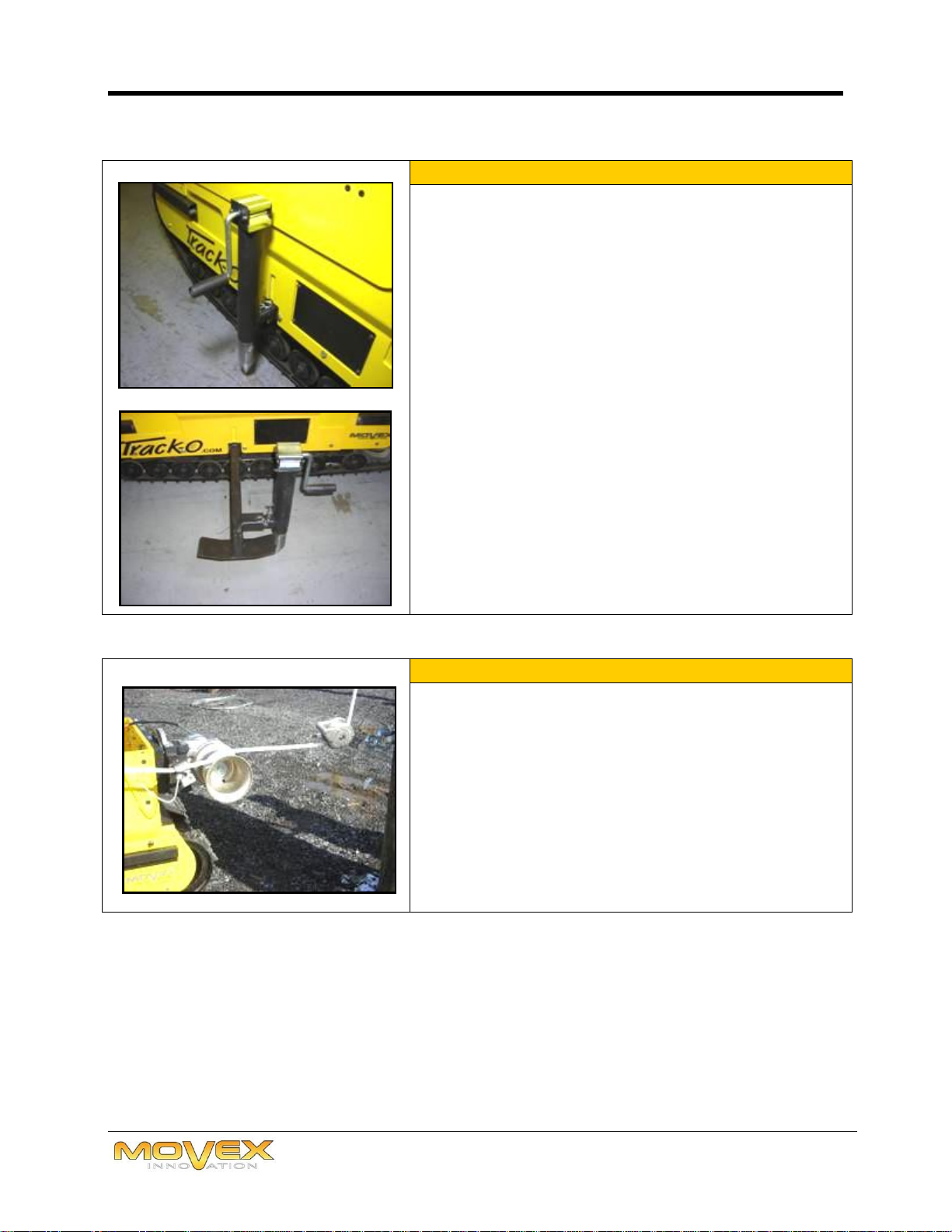
9 POSITIONING THE CAPSTAN - STORAGE MODE
The capstan has four positions: Two working
positions, one position for troubleshooting and
one position for storage.
Storage mode (used when carrying the Track-O to
a site).
10 POSITIONING THE CAPSTAN -
TROUBLESHOOTING MODE
The vertical position of the capstan can only be
used during repair/troubleshooting mode, i.e.:
To free the Track-O when bogged down or
whenever deemed necessary.
11 POSITIONING THE CAPSTAN -WORK MODE
Positioning the capstan-work mode :
1. Remove the retaining rod.
2. Slide the capstan sideway and tilt it
horizontally to the desired side.
3. Replace the retaining rod.
OPERATING MANUAL
Page 16 of 19
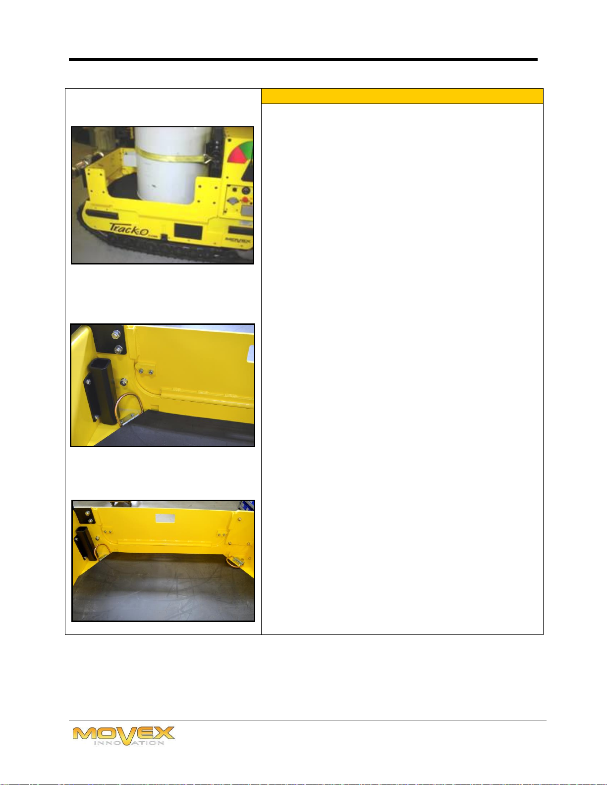
12 RETENTION MECHANISM FOR SLIPPERY GROUND
The retaining mechanism is used as needed to
stabilize the Track-O on slippery surfaces such as
ice, when using the capstan.
Retaining cylinders can be used in two ways,
directly on the chassis of the automotive Track-O
or on the safety skates
Lower the jacks so they lightly touch the ground,
without over lifting the Track-O.
13 INSTALLATION TO THE POLE
The capstan of the Track-O must be used at any
time with a pulley attached to the pole.
The capstan lever must be aligned as much as
possible with the cable axis.
IMPORTANT: DO NOT move the Track-O when the
winch is in use.

OPERATING MANUAL
Page 17 of 19
14 CONNNECTING THE CAPSTAN TO THE TRACK-O
Connecting the capstan to the Track-O :
1. Connect the pedal power cable to the capstan
2. Activate the inverter to power AC electrical
outlets The LED on the inverter will stay on for
4 hours. To reactivate it after this period, put
the switch to “OFF”and then switch back to
“ON”position.
3. Connect the other part of the cable (equipped
with a pedal) to the 120V outlet on the control
panel of the Track-O.
FEATURES
Page 18 of 19
CAPACITY of the Track-o
The automotive Track-O has been designed for rough terrain use. It is nonetheless
totally fit for back-lot access.
DESCRIPTION
DETAILS
Metric
Imperial
Width
76 cm
30 in.
Length
168 cm
66 in.
Weight
739.35 kg
1,630 lbs
Slow linear speed
6.7 m/min.
22 feet/min.
Fast line speed
13.4 m/min.
44 feet/min.
The Track-O is designed to work with an equivalent load of 2000 lbs / 907 kg. It can move
these loads over rough and sloped terrain. The Track-O’s integrated inclinometer
constantly indicates the degree of slope the Track-O can handle.
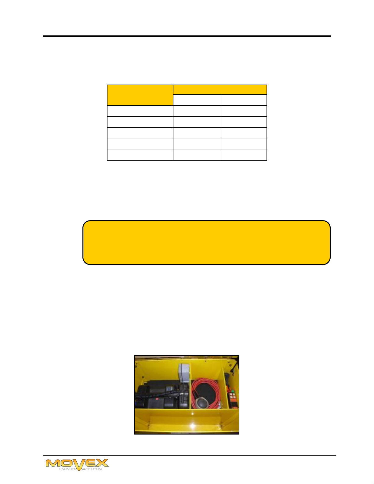
The storage comportment is ideal to put the Track-O’s accessories, such as the wireless
remote control, the wired control, the connection cable for the capstan and lighting
system.
Two 120 volts sockets are integrated in the trunk. The external socket is connected to
the inner socket which serves as protection and the other is independent and used to
charge the portable lamp.
Track-O’s charging time: 4 hours
Track-O’s continuous operating time: 4 hours
FEATURES CONT’D
Page 19 of 19
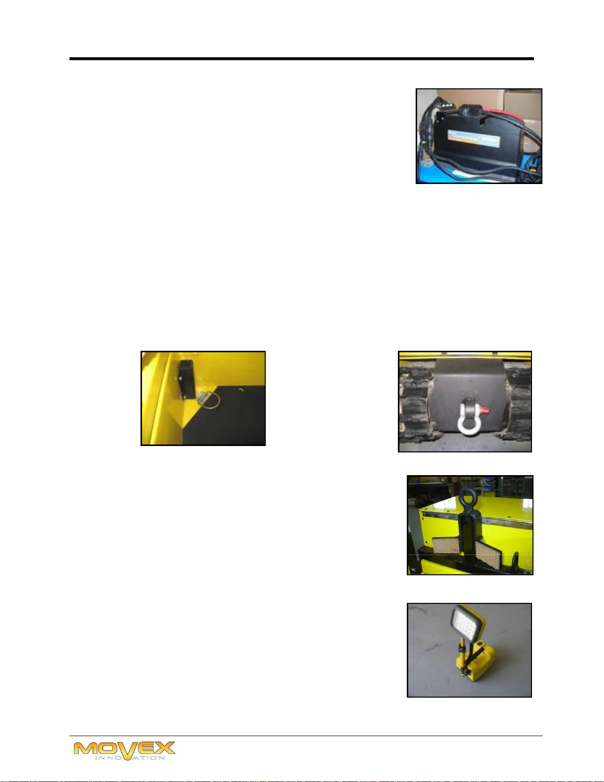
120 V Inverter
Capacity: Continuous 1000 W 15 A (3000 W peak)
Automatic shutdown conditions are:
The battery level reaches 21.2V;
The temperature of the inverter is too high;
There is a short-circuit on the 120VAC output;
Operation exceeds 4 hours;
Demand for power is too important;
The protection of 120V output inside the box has been triggered.
Track-O charging mode: Requires about 5A at 120V.
Recharge of the Track-O provides 25A to the accumulators.
D-Ring and skate support
Capacity: 200 lbs
Lifting and transformer support
Transformer support
Lifting support
Capacity: 2000 lbs
Lighting for night use (Option)
Two (2) intensity lighting
8 hours autonomy
Charging time: 4 hours
Recharges when in storage compartment and connected
to the outlet. However, the inverter must be activated
to initiate charging.
Towing eye
Capacity: 3100 lbs
Table of contents
Other Movex Industrial Equipment manuals


Popular Industrial Equipment manuals by other brands

MVP
MVP HVDG-2000 Operation manual

Exmark
Exmark ULTRAVAC Setup instructions

FRIEDHELM LOH
FRIEDHELM LOH Rittal SK 3363 Series Assembly and operating instructions

Teknomotor
Teknomotor 3140-B-DBS-P-ER20 Use and Maintenance Instruction

Magnescale
Magnescale DT32N instruction manual

riverhawk
riverhawk IM-186 instruction manual


