movistar VG-8050 User manual
VG-8050
Wireless Router - Access Point
User Manual
Version 1.4, October 2014
261097-011

1
Preface
This manual provides information related to the installation and operation of this
device. The individual reading this manual is presumed to have a basic
understanding of telecommunications terminology and concepts.
If you find the product to be inoperable or malfunctioning, please contact technical
For product update, new product release, manual revision, or software upgrades,
please visit our website at http://www.comtrend.com
Important Safety Instructions
With reference to unpacking, installation, use, and maintenance of your electronic
device, the following basic guidelines are recommended:
• Do not use or install this product near water, to avoid fire or shock hazard. For
example, near a bathtub, kitchen sink or laundry tub, or near a swimming pool.
Also, do not expose the equipment to rain or damp areas (e.g. a wet basement).
• Do not connect the power supply cord on elevated surfaces. Allow it to lie freely.
There should be no obstructions in its path and no heavy items should be placed
on the cord. In addition, do not walk on, step on, or mistreat the cord.
• Use only the power cord and adapter that are shipped with this device.
• To safeguard the equipment against overheating, make sure that all openings in
the unit that offer exposure to air are not blocked.
• Avoid using a telephone (other than a cordless type) during an electrical storm.
There may be a remote risk of electric shock from lightening. Also, do not use
the telephone to report a gas leak in the vicinity of the leak.
• Never install telephone wiring during stormy weather conditions.
CAUTION:
To reduce the risk of fire, use only No. 26 AWG or larger
telecommunication line cord.
Always disconnect all telephone lines from the wall outlet before servicing
or disassembling this equipment.
WARNING
Disconnect the power line from the device before servicing.
Power supply specifications are clearly stated in Appendix A.
Copyright
Copyright©2014 Comtrend Corporation. All rights reserved. The information
contained herein is proprietary to Comtrend Corporation. No part of this document
may be translated, transcribed, reproduced, in any form, or by any means without
prior written consent of Comtrend Corporation.
NOTE: This document is subject to change without notice.

2
Technical support
If you find the product to be inoperable or malfunctioning, please contact a technical
support engineer for immediate service by email at INT-support@comtrend.com
This program is free software: you can redistribute it and/or modify
it under the terms of the GNU General Public License as published by
the Free Software Foundation, either version 3 of the License, or
(at your option) any later version.
This program is distributed in the hope that it will be useful,
but WITHOUT ANY WARRANTY; without even the implied warranty of
MERCHANTABILITY or FITNESS FOR A PARTICULAR PURPOSE. See the
GNU General Public License for more details.
You should have received a copy of the GNU General Public License
along with this program. If not, see http://www.gnu.org/licenses/
Protect Our Environment
This symbol indicates that when the equipment has reached the end of
its useful life, it must be taken to a recycling centre and processed
separate from domestic waste.
The cardboard box, the plastic contained in the packaging, and the parts that make
up this router can be recycled in accordance with regionally established regulations.
Never dispose of this electronic equipment along with your household waste; you
may be subject to penalties or sanctions under the law. Instead, please be
responsible and ask for disposal instructions from your local government.

3
Table of Contents
CHAPTER 1 INTRODUCTION...........................................................................................................5
1.1 FEATURES..................................................................................................................................5
1.2 APPLICATION.................................................................................................................................6
CHAPTER 2 INSTALLATION.............................................................................................................7
2.1 HARDWARE SETUP...........................................................................................................................7
2.2 LED INDICATORS.............................................................................................................................9
CHAPTER 3 WEB USER INTERFACE............................................................................................11
3.1 DEFAULT SETTINGS .......................................................................................................................11
3.2 IP CONFIGURATION........................................................................................................................11
3.3 LOGIN PROCEDURE........................................................................................................................13
CHAPTER 4 BASIC USER INTERFACE.........................................................................................15
4.1 BASIC SETTINGS............................................................................................................................16
4.1.1 WAN Service ...................................................................................................................16
4.1.2 LAN Service....................................................................................................................17
4.1.3WiFi ................................................................................................................................19
4.1.4 Ports ...............................................................................................................................21
4.1.5 VoIP ................................................................................................................................23
4.1.6 Other functions...............................................................................................................24
4.1.7 Password change............................................................................................................27
4.1.8 Help ................................................................................................................................28
CHAPTER 5 ADVANCED USER INTERFACE...............................................................................29
5.1 WAN .............................................................................................................................................31
5.2 STATISTICS.....................................................................................................................................32
5.2.1 LAN Statistics..................................................................................................................32
5.2.2 WAN Service ...................................................................................................................33
5.3 ROUTE...........................................................................................................................................34
5.4ARP...............................................................................................................................................35
5.5 DHCP............................................................................................................................................36
5.6 NAT SESSION ................................................................................................................................36
5.7 IPV6 ..............................................................................................................................................37
CHAPTER 6 ADVANCED SETUP.....................................................................................................38
6.1 LAYER 2INTERFACE ......................................................................................................................38
6.1.1 ETH Interface.................................................................................................................38
6.2 WAN SERVICE ...............................................................................................................................39
6.3 LAN..............................................................................................................................................40
6.3.1 IPv6 Autoconfig.....................................................................................................................44
6.4 NAT ..............................................................................................................................................47
6.4.1 Virtual Servers ................................................................................................................47
6.4.2 Port Triggering...............................................................................................................48
6.4.3 DMZ Host .......................................................................................................................50
6.5 SECURITY ......................................................................................................................................51
6.5.1 IP Filtering .....................................................................................................................51
6.5.2 MAC Filtering.................................................................................................................55
6.5.3 Allowed MAC..................................................................................................................56
6.6 PARENTAL CONTROL......................................................................................................................58
6.6.1 Time Restriction..............................................................................................................58
6.6.2 URL Filter.......................................................................................................................59
6.7 ROUTING .......................................................................................................................................61
6.7.1 Default Gateway.............................................................................................................61
6.7.2 Static Route.....................................................................................................................62
6.7.3 Policy Routing ................................................................................................................63
6.7.4 RIP..................................................................................................................................64
6.8 DNS..............................................................................................................................................65
6.8.1 DNS Server.....................................................................................................................65

4
6.8.2 Dynamic DNS .................................................................................................................66
6.9 UPNP.............................................................................................................................................67
6.10 DNS PROXY/RELAY ....................................................................................................................68
6.11 IPTUNNEL...................................................................................................................................68
6.11.1 IPv6inIPv4...........................................................................................................................68
6.11.2 IPv4inIPv6...........................................................................................................................70
6.11.3 GRE......................................................................................................................................72
6.12 IPSEC ..........................................................................................................................................74
6.13 CERTIFICATE................................................................................................................................77
6.13.1 Local...............................................................................................................................77
6.13.2 Trusted CA......................................................................................................................79
6.14 MULTICAST..................................................................................................................................81
6.15TVSERVICES...............................................................................................................................84
CHAPTER 7 WIRELESS 2.4G BAND...............................................................................................85
7.1 BASIC ............................................................................................................................................85
7.2 SECURITY ......................................................................................................................................87
7.2.1 WPS ................................................................................................................................90
7.3 MAC FILTER .................................................................................................................................94
7.4 WIRELESS BRIDGE.........................................................................................................................95
7.5ADVANCED ....................................................................................................................................96
7.6 STATION INFO ..............................................................................................................................100
CHAPTER 8 VOICE..........................................................................................................................101
8.1 SIP BASIC SETTING ...............................................................................................................102
8.1.1 Global Parameters .......................................................................................................102
8.1.2 Service Provider ...........................................................................................................103
8.2 SIPADVANCED......................................................................................................................105
8.2.1 Global Parameters .......................................................................................................105
8.2.2 Service Provider .........................................................................................................106
8.3 SIP DEBUG............................................................................................................................108
8.3.1 Global Parameters .......................................................................................................108
8.3.2 Service Provider ...........................................................................................................109
8.4 TELEPHONE CALLS....................................................................................................................110
CHAPTER 9 DIAGNOSTICS........................................................................................................... 111
CHAPTER 10 MANAGEMENT ......................................................................................................112
10.1 SETTINGS...................................................................................................................................112
10.1.1 Backup Settings.............................................................................................................112
10.1.2 Update Settings............................................................................................................. 113
10.1.3 Restore Default............................................................................................................. 113
10.2 SYSTEM LOG .............................................................................................................................114
10.3 SECURITY LOG ..........................................................................................................................116
10.4TR-069 CLIENT .........................................................................................................................117
10.5 INTERNET TIME .........................................................................................................................119
10.6ACCESS CONTROL .....................................................................................................................120
10.6.1 Passwords.....................................................................................................................120
10.7WAKE-ON LAN .........................................................................................................................121
10.8 UPDATE SOFTWARE ...................................................................................................................122
10.9 REBOOT.....................................................................................................................................123
APPENDIX A – SPECIFICATIONS ................................................................................................124
APPENDIX B – PIN ASSIGNMENTS.............................................................................................126
APPENDIX C – SSH CLIENT..........................................................................................................127
APPENDIX D – FIREWALL ............................................................................................................128
APPENDIX E – WPS EXTERNALREGISTRAR..........................................................................131
APPENDIX F - CONNECTION SETUP..........................................................................................136

5
Chapter 1 Introduction
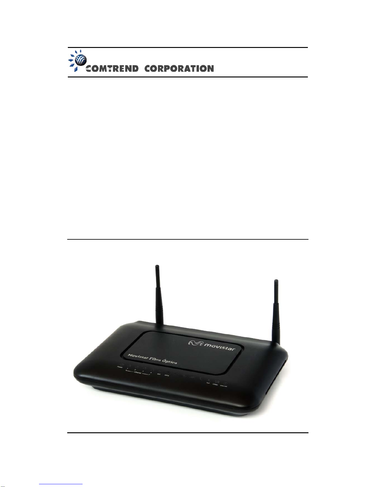
The VG-8050 is an 802.11n 2.4GHz compliant VoIP Gateway. It employs a
10/100/1000 Base-T Gigabit Ethernet port for WAN, four 10/100/1000 Base-T
Gigabit Ethernet ports for LAN, one FXS port, one 2.4GHz WiFi On-Off/WPS
button, and an integrated 802.11n 2.4GHz (2T2R) for WLAN Access Point (AP),
which is backward compatible with 802.11b/g; therefore VG-8050 allows both
wired LAN connectivity and wireless connectivity. It is also capable of
facilitating predictable, real-time, toll-quality voice over the Internet.
VG-8050 connects to ADSL or GPON (Gigabit-Capable Passive Optical
Network) modem for providing VoIP services. It supports state-of-the-art
security features such as WPA data encryption, Firewall & VPN pass through
and is designed for both residential and business applications that require
wireless and wired connectivity. VG-8050 is also designed with TR-068
compliant color panel and LED indicators for easy installation and
user-friendliness.
1.1 Features
•UPnP
•Integrated 802.11n 2.4GHz AP (Backward
compatible with 802.11g/b)
•WPA/WPA2 and 802.1x
•WMM
•RADIUS client
•IP filtering
•Static route routing functions
•Dynamic IP assignment
•Parental Control
•IGMP Proxy
•DHCP Server/Client
•DHCP Server/Client
•DNS Relay
•Supports remote administration
•Configuration backup and restoration
•FTP/TFTP server
•Supports QoS (Quality of Service) for voice
•Supports caller ID display and restriction
•Supports call hold, call waiting, call
forwarding, call transfer, 3-way conference
•Supports Direct number dialing
•Supports T.38/ TR-069

6
1.2 Application
The following diagram depicts the application of the VG-8050.

7
Chapter 2 Installation
2.1 Hardware Setup
Follow the instructions below to complete the hardware setup.
BACK PANEL
The figure below shows the back panel of the device.
Power ON
Press the power button to the OFF position (OUT). Connect the power adapter to the
power port. Attach the power adapter to a wall outlet or other AC source. Press the
power button to the ON position (IN). If the Power LED displays as expected then
the device is ready for setup (see section 2.2 LED Indicators).
Caution 1: If the device fails to power up, or it malfunctions, first verify that the
power cords are connected securely. Then power it on again. If the
problem persists, contact technical support.
Caution 2: Before servicing or disassembling this equipment, disconnect all power
cords and telephone lines from their outlets.
Telf
For VoIP service, connect telephone(s) to these ports with RJ11 cable.
Reset Button
Restore the default parameters of the device by pressing the Reset button during 5
seconds. The device will reboot. After the device has rebooted successfully, the front
panel should display as expected (see section 2.2 LED Indicators).
NOTE: If pressed down for more than 20 seconds, the VG-8050 will go into a
firmware update state (CFE boot mode). The firmware can then be
updated using an Internet browser pointed to the default IP address.
LAN PORTS
Use 1000-BASE-T RJ-45 cables to connect up to four network devices to a Gigabit
LAN, or 10/100BASE-T RJ-45 cables for slower networks. As these ports are
auto-sensing MDI/X, either straight-through or crossover cable can be used.
Internet
This port has the same features as the LAN ports described above with additional
Ethernet WAN functionality.

8
WiFi/WPS Button
This button is used to enable/disable WiFi and WPS.
If pushed for 2 seconds it will enable/disable the wireless functionality.
If pushed for 5 seconds or longer, it will activate the WPS functionality.

9
2.2 LED Indicators
The front panel LED indicators are shown below and explained in the following table.
This information can be used to check the status of the device and its connections.
LED Color Mode Description
POWER
Green
On Power on
Red
Blinking
2Hz Red
Failure Power On Self Test
Off Power off
Ethernet
1x~4x
Green On Ethernet connection is available
Blink LAN activity present (traffic in either direction)
Off Ethernet connection is not available
WiFi Green On WiFi connection is available
Blink Negotiation or traffic on line
Off WiFi connection is not available
WPS
Green
On
(120 sec) WPS window enabled
Blink WPS negotiation on going
Off WPS enabled but WPS window inactive
Red
Solid
Red
(20 sec)
Problems on WPS Registration
Telf1
Green
Blinking
Negotiation or VoIP traffic presence.
Solid
VoIP configuration OK, ATA has been
registered in proxy SIP
Quick
blinking
Tx/Rx traffic on line
Off No VoIP configuration
10
Red Solid
VoIP configuration error, ATA can’t register in
proxy SIP
Línea
Green On Line up
Off WAN cable disconnected
Internet
Green
Blink PPP/DHCP negotiation
Solid PPP/DHCP Up
Quick
Blinking
Tx/Rx traffic on line
Off No Inter
net connection (WAN cable
disconnected or PPP interface deleted)
Red Solid
Red Authentication failed
NOTE: During a FW Upgrade both the POWER and Internet LEDs will blink at 2Hz
(Green Color). This blinking will indicate that the Flash memory is being
overwritten. After the FW upgrade the router will reboot automatically.

11
Chapter 3 Web User Interface
This section describes how to access the device via the web user interface (WUI)
using an Internet browser such as Internet Explorer (version 5.0 and later).
3.1 Default Settings
The factory default settings of this device are summarized below.
LAN IP address: 192.168.1.1
LAN subnet mask: 255.255.255.0
Administrative access (username: 1234 , password: 1234)
WLAN access: enabled
Technical Note
During power on, the device initializes all settings to default values. It will then
read the configuration profile from the permanent storage section of flash memory.
The default attributes are overwritten when identical attributes with different values
are configured. The configuration profile in permanent storage can be created via
the web user interface or telnet user interface, or other management protocols.
The factory default configuration can be restored either by pushing the reset button
during 5 seconds until the power indicates LED blinking or by clicking the Restore
Default Configuration option in the Restore Settings screen.
3.2 IP Configuration
DHCP MODE
When the VG-8050 powers up, the onboard DHCP server will switch on. Basically,
the DHCP server issues and reserves IP addresses for LAN devices, such as your PC.
To obtain an IP address from the DCHP server, follow the steps provided below.
NOTE: The following procedure assumes you are running Windows XP.
However, the general steps involved are similar for most operating
systems (OS). Check your OS support documentation for further details.
STEP 1: From the Network Connections window, open Local Area Connection (You
may also access this screen by double-clicking the Local Area Connection
icon on your taskbar). Click the Properties button.
STEP 2: Select Internet Protocol (TCP/IP) and click the Properties button.
STEP 3: Select Obtain an IP address automatically as shown below.

12
STEP 4: Click OK to submit these settings.
If you experience difficulty with DHCP mode, you can try static IP mode instead.
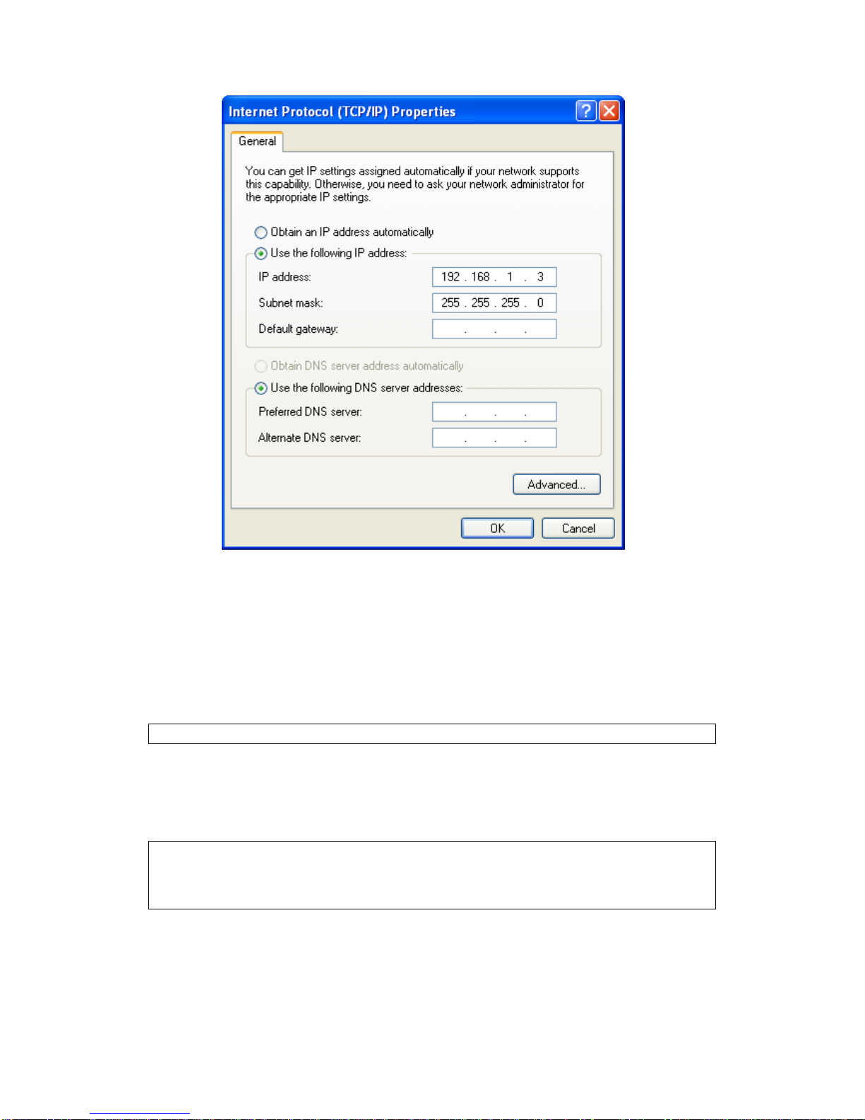
STATIC IP MODE
In static IP mode, you assign IP settings to your PC manually.
Follow these steps to configure your PC IP address to use subnet 192.168.1.x.
NOTE: The following procedure assumes you are running Windows XP.
However, the general steps involved are similar for most operating
systems (OS). Check your OS support documentation for further
details.
STEP 1: From the Network Connections window, open Local Area Connection (You
may also access this screen by double-clicking the Local Area Connection
icon on your taskbar). Click the Properties button.
STEP 2: Select Internet Protocol (TCP/IP) and click the Properties button.
STEP 3: Change the IP address to the 192.168.1.x (1<x<255) subnet with subnet
mask of 255.255.255.0. The screen should now display as shown below.
13
STEP 4: Click OK to submit these settings.
3.3 Login Procedure
Perform the following steps to login to the web user interface.
NOTE: The default settings can be found in section 3.1.
STEP 1: Start the Internet browser and enter the default IP address for the device
in the Web address field. For example, if the default IP address is
192.168.1.1, type http://192.168.1.1.
NOTE: For local administration (i.e. LAN access), the PC running the browser
must be attached to the Ethernet, and not necessarily to the device.
For remote access (i.e. WAN), use the IP address shown on the Device
Information screen and login with remote username and password.
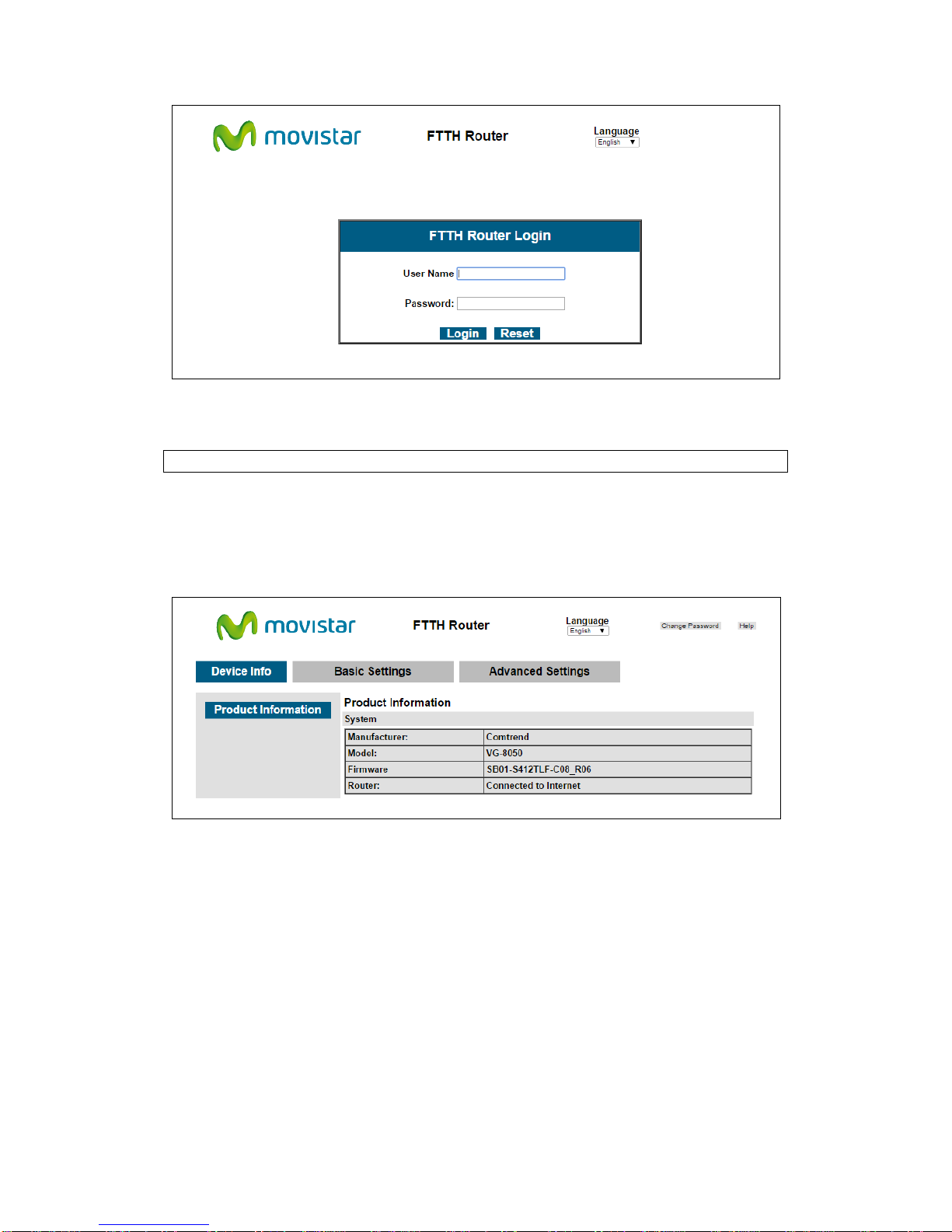
STEP 2: A dialog box will appear, such as the one below. Enter the default
username and password, as defined in section 3.1 Default Settings.
14
Click Login (or Acceso) to continue.
NOTE: The login password can be changed later (see section 4.1.7)
STEP 3: After successfully logging in for the first time, you will reach this screen.
15
Chapter 4 Basic User Interface
The Basic Web User Interface is divided into 3 navigation tabs (Device Info, Basic
Settings, Advanced Settings). By selecting each of these tabs it opens a submenu
with more selections.
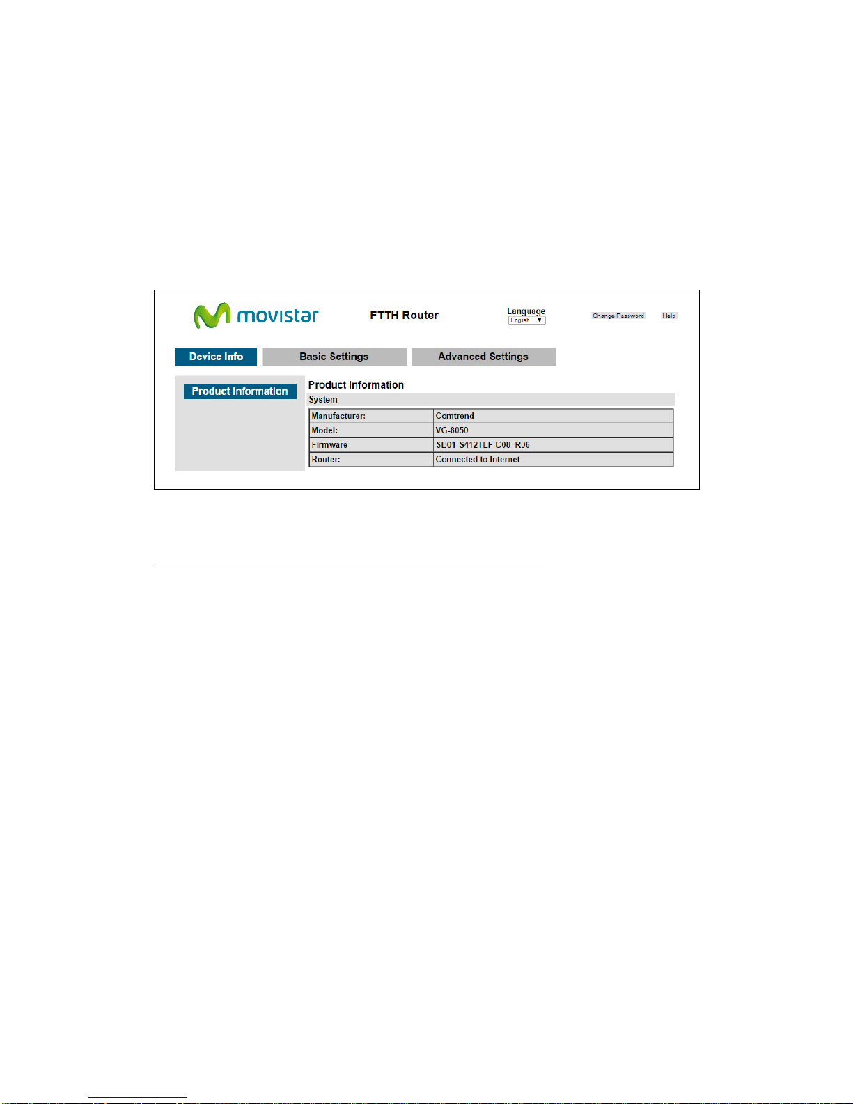
Device Info is the first selection on the main menu so it will be discussed first.
Subsequent chapters will introduce the other main menu options in sequence.
The Product Information screen will display at startup.
This screen shows the manufacturer, hardware model, software version and IP
settings and other related information.
There are 2 languages available for the Basic User Interface (Spanish and English),
to change between languages simply click on the drop down Language (or Idioma)
and select the language you prefer.
16
4.1 Basic Settings
By clicking on the tab ‘Basic Settings’ you’ll be able to configure the different
common settings of your network.
These settings are divided into different categories on the left side of the window.
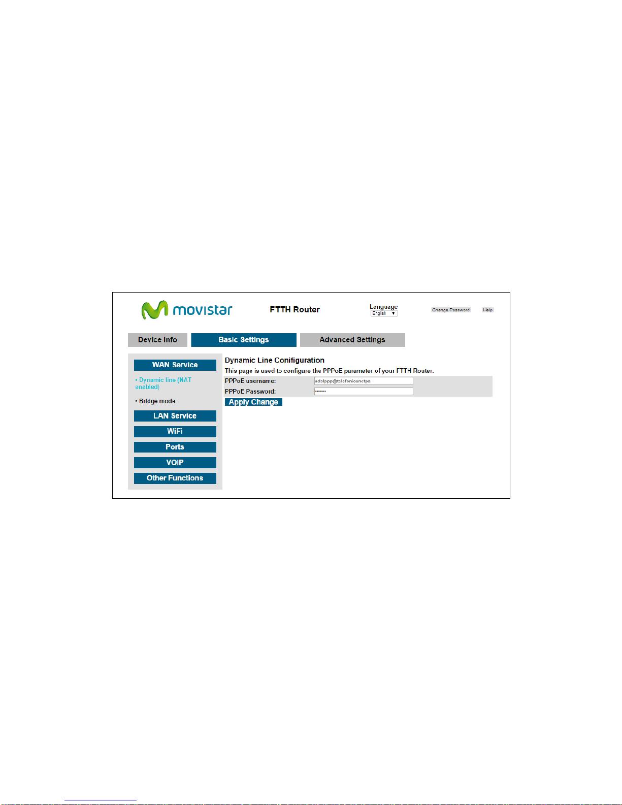
4.1.1 WAN Service
This option will allow you to set the PPP configuration or, on the contrary to disable
the WAN PPP client in order to use an external client/router (Bridge mode)
By clicking on “Dynamic line (NAT enabled)” the following menu will appear:
There you can set a different PPP username and password. To set the new values
press on ‘Apply Change’.
By clicking on “Bridge mode” the following menu will appear:
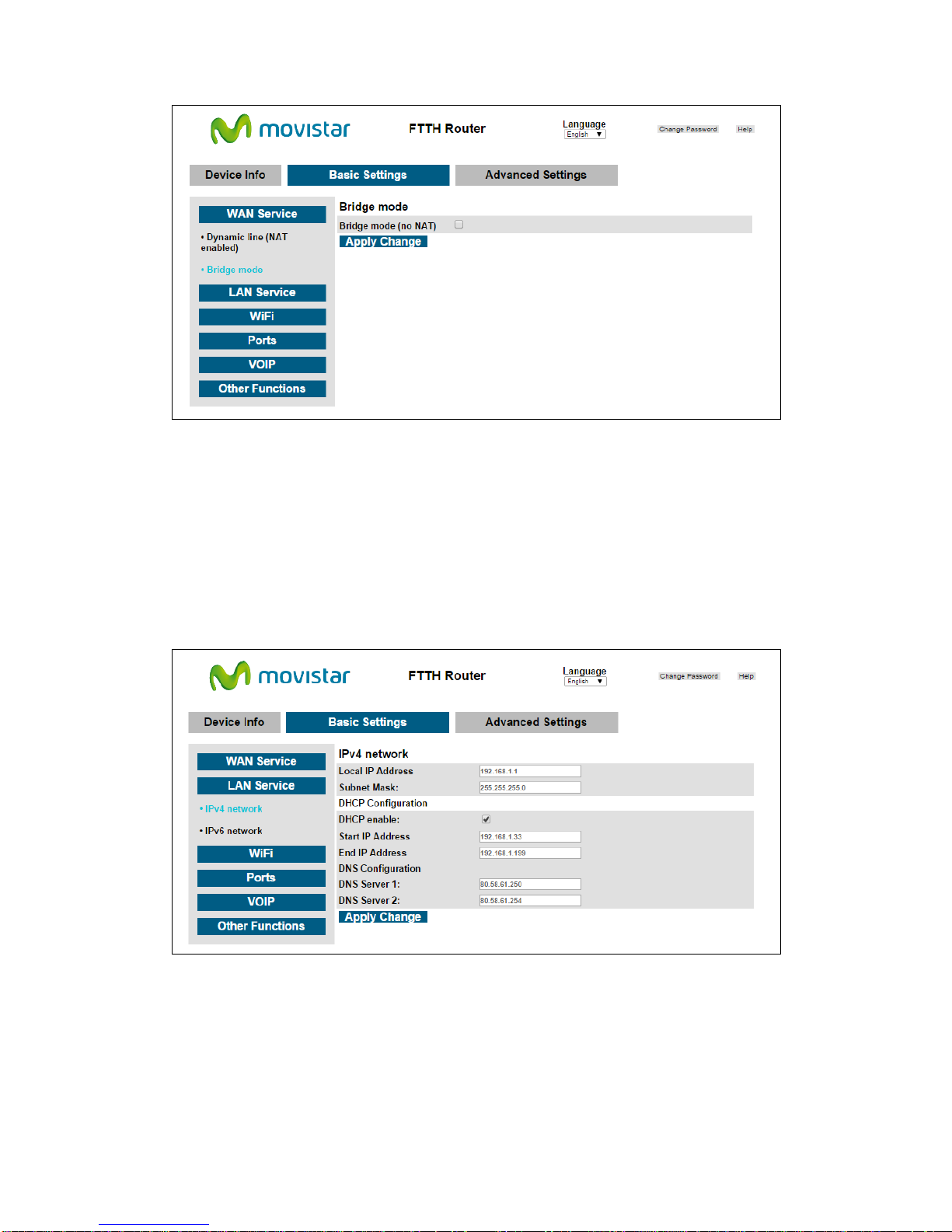
17
To disable the PPP client to be able to connect an external client or an external
Router mark the option “Bridge mode (no NAT)” and press ‘Apply Changes’.
4.1.2 LAN Service
This menu allows changing the local IP address, modify the DHCP server range or
configure the IPv6 LAN network.
By clicking on “IPv4 network” the following LAN IP options will be configurable:
In this menu you’ll be able to configure the following parameters:
IP Address: Input the IP address for the LAN port.
Subnet Mask: Input the subnet mask for the LAN port.
DHCP Configuration: To enable DHCP, select Enable DHCP and enter Start and
End IP addresses. This setting configures the router to

18
automatically assign IP, default gateway and DNS server addresses
to every PC on your LAN.
DNS Server 1: The Primary DNS server which is delivered to the LAN site
hosts via DHCP protocol.
DNS Server 2: The Secondary DNS server which is delivered to the LAN
site hosts via DHCP protocol.
To configure the LAN IPv6 network you need to click on “IPv6 network”:
Local IPv6 Address Configuration
Heading
Description
EUI-64 Use EUI-64 algorithm to calculate link-local address from MAC
address
User Setting
Use the Interface Identifier field to define a link-local address
Global IPv6 Address Configuration
Heading
Description
Interface Address
(prefix length is
required):
Configure static LAN IPv6 address and subnet prefix
length
DHCPv6 Configuration
Heading
Description
Autoconfiguration
Use stateless configuration
Fixed Range
Use stateful configuration
Start interface ID: Start of interface ID to be assigned to dhcpv6
client
End interface ID: End of interface ID to be assigned to dhcpv6
client

19
4.1.3 WiFi
This option allows you to configure basic features of the wireless LAN interface. You
can enable or disable the wireless LAN interface, hide the network from active scans,
set the wireless network name (also known as SSID) and restrict the access to your
wireless network based on the physical addresses of the clients.
The WiFi option is divided in 3 simple menus:
“2.4GHz network”:
Consult the table below for descriptions of these options.
Option
Description
Enable wireless
interface
A checkbox
that enables or disables the wireless LAN
interface. When selected, the wireless network is enabled.
SSID
[1-32 characters]
Sets the wireless network name. SSID stands for Service Set
Identifier. All stations must be configured with the correct
SSID to access the WLAN. If the SSID does not match, that
user will not be granted access.
Hide SSID Select Hide SSID to protect the access point from detection by
wireless active scans. To check AP status in Windows XP, open
Network Connections from the start Menu and select View
Available Network Connections. If the access point is
hidden, it will not be listed there. To connect a client to a hidden
access point, the station must add the access point manually to
its wireless configuration.
Channel number Select in the drop down the channel number you wish to use for
your wireless network. If you have no preference you can select
‘Auto’ and the router will automatically select the best channel.
Click Apply Change to implement new configuration settings.
“Security”:
Table of contents
Other movistar Wireless Router manuals


