MP3 WXH Series User manual
CIRCULAR SERIES WXH - 1500Pa
Cert. N° 1812-CPR-1189
Technical Manual
English
WXH
SINGLE COMPARTMENT
SMOKE CONTROL DAMPER

2
Smoke damper
rev 21-10
Description
Damper WXH is a single compartment smoke control damper; It’s a device which can be open or closed
to control the ow of smoke and hot gasses into, from or within a duct for use in single compartment
applications at elevated temperatures (600°C), which may be associated with smoke control ducts to
EN1366-9:2008.
The function of the single compartment smoke control damper is to concentrate the fan pressure in the
smoke reservoirs involved in the re scenario.
The damper casing is made of galvanized steel with EPDM connection with leakage class C according with
EN1751.
The damper has two dierent motorized versions depending on the relay response required: type AA
(Automatic Activation) and type MA (Manual Activation, with re rated motor covering box). The smoke
damper is CE marked according to EN12101-8, tested according to EN1366-10 and classied according to
EN13501-4. The damper is suitable for vertical and horizontal installation in single compartment smoke
duct evacuation systems with maximum temperature of 600°C for 2 hours with smoke leakage class S at
1500Pa negative pressure.
Declaration of performance
The damper is CE marked with the declaration of performance according to EN12101-8 as a circular smoke
control damper single compartment with CPR nr. 1812-CPR-1189.
Manufacturer of the smoke damper:
MP3 S.r.l., via G. La Pira 9, 35012 Camposampiero (PD), Italy
Intended use
The damper is a part of a smoke and re protection system that is designed to reach the following targets:
• Extract smoke for 2 hours during the re
• Reduce temperatures during the re
• Opens the blade and remove heat and smoke from a compartment in re
• Closes the blade to prevent the spread of heat and smoke to a safe compartment
• Create an non-smoke layer
• Protect the property
This damper represents a part of the smoke and re protection project whose main purpose is to be
WXHU AA WXHU MA
3
Smoke damper
rev 21-10
installed in single compartment smoke ducts to concentrate all the depression of the smoke extraction
fan in the smoke reservoirs actually aected by the presence of smoke. This re protection project shall be
designed by a re expert. The products used in system should not be larger than dimension Ø 630.
Testing and classication
The WXH single compartment smoke control dampers have been tested connected to single compart-
ment circular ducts and ttings belonging to the Lindab (www.lindab.com) smoke and heat exhaust
ventilation system.
WXH smoke control dampers have two relay response options: type AA (Automatic Activation) and type
MA (Manual Activation).
In accordance with EN12101-8:2011 WXH single compartment smoke control dampers have been subjec-
ted to the following tests:
- Opening and closing cycles according to EN1366-10:2011+A1:2017: 10000 cycles at nominal operating
supply, 100 cycles at nominal operating supply -10%, 100 cycles at nominal operating supply +15%.
- Blade and casing ambient leakage according to EN1751:2014 with pressure from -2000Pa to +2000Pa
obtaining the classication in class 2 for the air tightness of the blade and class C for the air tightness of
the casing.
- Extraction system ambient leakage according to EN1366-10:2011+A1:2017 with pressure -1500Pa (level
3).
- 600°C temperature resistance according to EN1366-10:2011+A1:2017 with pressure -500Pa (level 3)
for 120 minutes with damper installation both horizontal and vertical and with blade rotation axis both
horizontal and vertical.
The re classication obtained according to EN13501-4:2016 is:
According to the classication obtained, according to Tables 1 and 3 (level 3) and according to paragraph
6.3.2.2 of EN1366-10:2011+A1:2017 it is allowed to use single compartment smoke control dampers WXH:
- In single compartment smoke exhaust ventilation system;
- In general HVAC systems as well as a smoke control system;
- With depression for smoke exhaust up to -500Pa;
- With pressure at ambient temperature from -1500Pa to +500Pa.
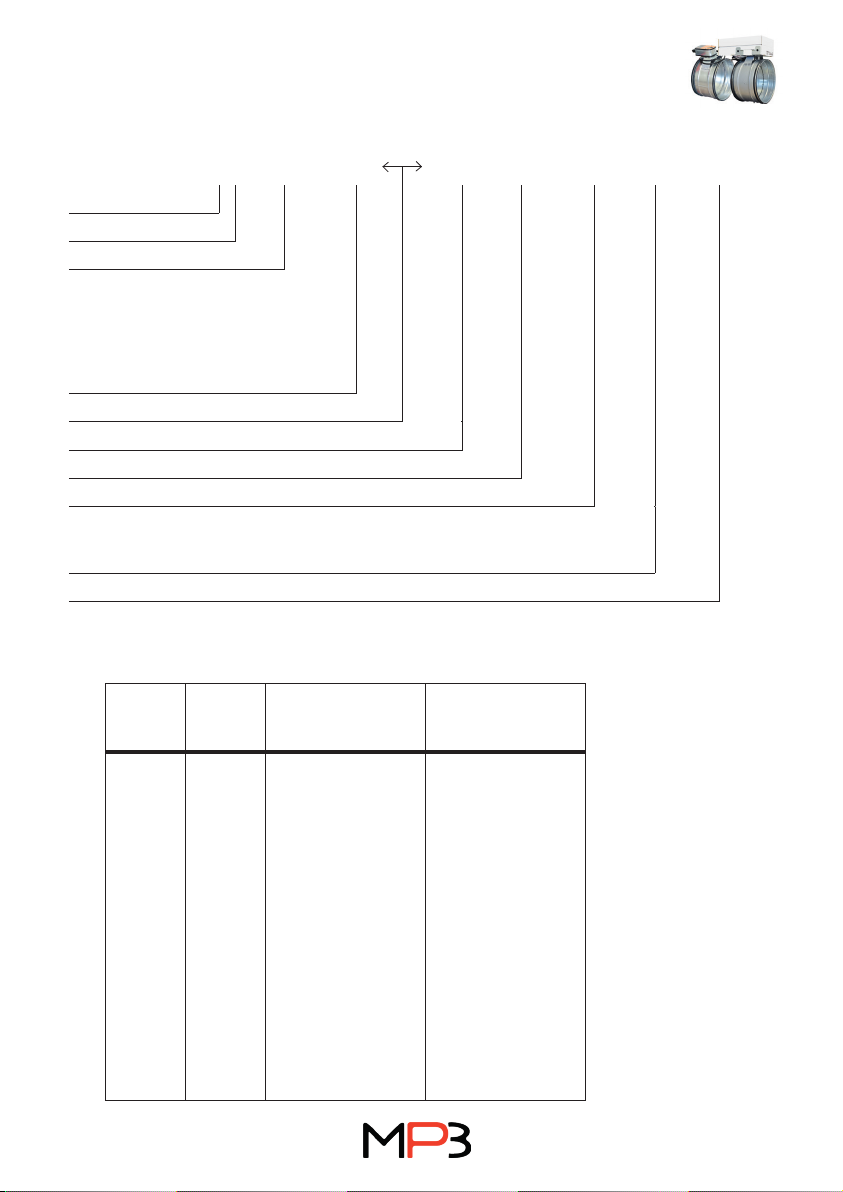
E I t Ved ho i o S Operating pressure C MA/
AA
Single/
multi
E6oo - 120 ved hod i o S -1500 Pa to 500 Pa 10000 MA single
E6oo - 120 ved hod i o S -1500 Pa to 500 Pa 10000 AA single
According to par. 9.7.1 of EN1366-10:2011+A1:2017, single compartment smoke control dampers may be
applied to ducts that have been tested to EN 1366-9, constructed from materials of the same density as
those tested or of the same material with a greater density or thickness.
Single compartment smoke control dampers may be applied to builders work (created on site) ducts,
concrete or aerated concrete ducts and walls, provided that the single compartment smoke control
damper has been tested on a duct or in a wall constructed from materials of lower density and thickness
(e.g. boards or sheet steel), provided that the concrete/aerated concrete construction has a thickness that
complies with the supporting construction information shown in EN 1363-1 and EN 1366-2 for the time
period of classication required. Correct re resisting fasteners to suit the materials shall be used.
4
Smoke damper
rev 21-10
Dimension
Ød
nom
l
mm
Type AA Type MA
a
mm
m
kg
a
mm
m
kg
100 100 250 3,2 376 5,7
125 100 250 3,4 376 5,9
160 100 250 3,6 376 6,1
200 100 250 3,9 376 6,4
250 100 270 4,5 379 7,0
315 100 270 5,2 379 7,7
355 100 270 5,5 379 8,0
400 100 290 6,8 399 9,3
450 100 290 8,1 399 10,6
500 115 298 9,5 407 12,0
560 115 298 11,0 407 13,5
630 115 298 12,5 407 15
Classication details
E600 120 (ved,hodi S 1500Pa C10000 AA single
E = integrity
Temperature
Time
ved = Installation on duct penetrating a
vertical wall
hod = Installation on duct penetrating a
horizontal wall
origin of re is irrelevant
Smoke leakage <5 (m3/h)/m2
Maximum negative pressure
Motor cycles use in combined smoke control and HVAC system
Relay response
Type AA = Automatic Activation
Type MA = Manual Activation
Single compartment
o)

5
Smoke damper
rev 21-10
a
65
l
Ød
94
Type AA Ø 100-630 mm Type MA Ø 100-630 mm
a
133
l
Ød
203
164
Transport and delivery
The transport is performed by common transport means. Components that are free loaded should be
secured in such a way that any deformation and damage to the components will be eliminated. The trans-
port vehicle must be covered to prevent dust, debris and humidity to damage the components.
Components are delivered without an acceptance at a supplier´s as default. If an acceptance at a
supplier´s is required, it is necessary to state this requirement in the orderpurchase contract.
A buyer or his/her representative is obliged in terms of good acceptance to on site check these according
to the delivery documentation. Visible defects and amount shortages are to be noticed in the transporter’s
transport sheet immediately.
Storage
The goods should be stored inside and protected to prevent dust, debris and humidity to damage the
goods.
Before mounting
Before starting the mounting of the damper it is necessary to inspect all components to make sure that
they are correct according to the project documentation and to make sure they have not been damaged
during transport or storage. When handling the products on site it is important to be careful so that they
don’t get damaged and their properties change.
Mounting of the damper should only be done by trained professionals equipped with the correct protec-
tive equipment and tools. The mounting of the damper should always be performed according to valid
documentation from the manufacturer.
The damper should never be used as a supporting part of the building.
In order to achieve a good result, ensure you have:
• A well-organised and protected storage site for components and other parts that are to be assemb-
led.
• A properly planned assembly sequence in accordance with the instructions.
6
Smoke damper
rev 21-10
Preparations:
• Cut ducts at right angles.
• Carefully remove any burrs from cut edges. Installation is
easier and the risk of damaging the gasket is reduced if there
are no burrs.
• Cut away the needles created from the fold.
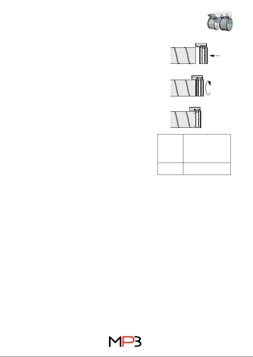
Assembly
• Start by inserting the turned-over edge of the damper into
the duct.
• Check that the rst lip of the gasket is in contact with the
edge of the duct all the way around and sticks straight out so
that the lip is not twisted in one direction or the other.
• Push the end of the damper into the duct. Twisting the
damper slightly aids insertion.
• Secure the damper in the duct using self-tapping screws
Ø4,2×13.
• Fasteners should be positioned on the duct close the damper
(minimum 10-15 mm) to support itself weight and to prevent
damage to the gasket.
• The damper must be installed on certi ed and CE marked
smoke control system.
Ø
nom
Minimum number
of fasteners
required to achieve
sucient strength.
100-630 4
Mounting
Technical data for the motors
BLE motor BLE24 BLE230
Power supply.................................... AC/DC 19.2 28,8 V,
50/60 Hz
AC 198-264 V,
50/60 Hz
Power consumption.......................... 7,5 W 5 W
For wire sizing................................... 9 VA 12 VA
Connection........................................ Cable 1 m, 3×0,75 mm2Cable 1 m, 3×0,75 mm2
Operative angle................................ Max. 90° Max 105°
Torque at rated voltage..................... Min. 15 Nm Min. 15 Nm
Direction of rotation.......................... Selected by mounting L/R Selected by mounting L/R
Position indication............................ Mechanical with pointer Mechanical with pointer
Running time.................................... <30 s for 90° <30 s for 90°
Sound power level........................... Max. 62 dB (A) Max. 62 dB (A)
Protection class................................ III Safety extra-low voltage II totally insulated
Protection type................................. IP 54 IP54
Ambient temperature range.............. -30 to +50°C -40 to + 80°C
Ambient moisture.............................. 95 % RH 95 % RH

7
Smoke damper
rev 21-10
<3° <87°
3S1 S2 S3 S4 S5 S6
2
2
1
1
–+
~
T
<3° <87°
S1 S2 S3 S4 S5 S6
NL1
3
2
2
1
1
Note
Caution: Main power supply voltage!
Parallel connection of several actuators possible.
Power consumption and switching thresholds must
be observed!
Note
Supply via safety isolation transformer!
Parallel connection of several actuators possible.
Power consumption and switching thresholds must
be observed!
2-wire open-close control. The actuator is overload-proof and
can thus remain energized even at the end stops.
Two microswitches with xed settings are installed in the
actuator for indicating the damper end positions. The position
of the damper blade can be read o on a mechanism position
indicator.
The crank handle supplied with the actuator allows it to be
operated manually.
Mode of operation.................................
Signalling .................................................
Manual operation....................................

8
Smoke damper
rev 21-10
Electric cables and system
For Manual Activation version (MA), the electric cables and system must be protected and designed to
have at least 30 minutes circuit integrity.
Operation
All smoke dampers have a electrical actuator. They are designed to be installed indoor in a smoke evacua-
tion and reversable HVAC system.
Before starting the system it is necessary to check the system for damages and that it is consistent to the
re expert design.
Checking and Maintenance
Following features shall be checked up during a revision of the damper at least once every six months:
• All parts are to be installed according to this mounting instruction.
• The damper must not be damaged in any way, the cross-section of the casing, the motor and the
covering box of the motor must not be damaged in any way.
• All connections with the smoke evacuation system are to be tightened and properly connected.
• The ducts connected to the damper must be suspended or supported in order to bear the damper’s
weight too.
• There must not be any ammable bodies on the damper surface and 50 mm away from the system
itself.
Periodic inspection and cleaning
Periodic inspection shall be performed in accordance with the requirements of the law or by the building
regulations or other local regulations.
In the absence of specic regulations (or to their complement), in accordance with point 8.3 of the EN
12101-8 standard, it is recommended to carry out the following controlactivities at intervals of no more
than 6 months: execute an opening and closing test and check the correct movement of the blade and the
correct functioning of the microswitches (limit switches). Blade opening time shall be not more than 60
seconds. Blade closing time shall be not more than 60 seconds.
Together with the control activities, it is recommended to visually verify the absence of corrosion, the
integrity of the electrical wiring and the sealing of the construction support. Damper cleaning is included
in the ordinary maintenance activities of the ventilation ducts. Smoke control dampers can be cleaned
with a dry or wet cloth. In the case of resistant dirt, it is possible to use normal household detergents. If
prescribed for the type of building, it is possible to use disinfectant detergents. The use of detergents or
mechanical abrasive cleaning systems is not permitted. These indications comply with the standards EN
12101-8 annex B and EN 15423 annex C.

9
Smoke damper
rev 21-10
WXHU SAA D00 200
Type
Relay response
Motor type
Dimension Ød
Ordering example
Repair
For safety reasons, repair activities involving re-ghting components must be carried out only by qua-
lied personnel. only original spare parts supplied by the smoke control damper manufacturer must be
used.
A functional test must be performed after each repair.
At the end of the inspection, cleaning or repair operations, check that the smoke control damper is in the
normal operating position. Keep records of all inspections, repair activities, any problems encountered
and their resolution. This practice, even when not mandatory, is very useful in practice.
Disposal
Disposal must be carried out in accordance with national legislation. For electrical and electronic parts
also refer to EU Directive 2011/65
Type WXH Circular smoke damper
Connection U EPDM gasket
Relay Response
SAA Automatic Activation
(Single compartment)
MAS Manual Activation
(Single compartment)
Motor type
V00 Belimo BLE24 V AC/DC
D00 Belimo BLE230 V AC
Dimension XYZ Nominal diameter (mm)
Product code
This manual suits for next models
2
Table of contents
Popular Fire And Smoke Damper manuals by other brands

mercor
mercor mcr FID PRO Series Operation and maintenance manual

Greenheck
Greenheck HPR Series Installation, operation and maintenance manual

Orlaco
Orlaco 0701200 installation manual

Trox Technik
Trox Technik AKK Assembly and operating instructions

TAKACHIHO
TAKACHIHO FYN-M 1 Series manual

BSB
BSB FSD-C Installation, operating, & maintenance instructions


