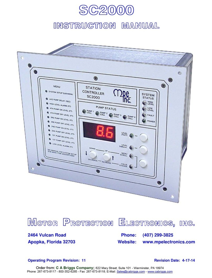
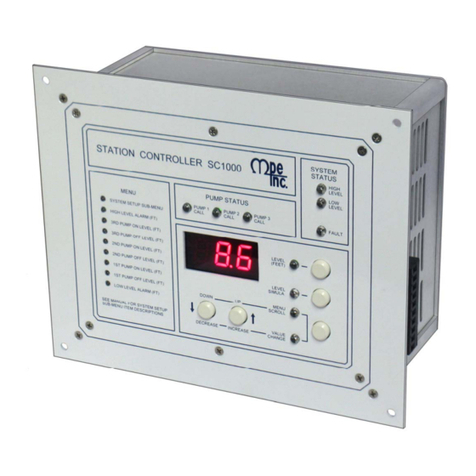
MPE SC2000 User manual

INSTRUCTION MANUAL
STATION CONTROLLER SC2000
MOTOR PROTECTION ELECTRONICS, INC.
2464 Vulcan Road, Apopka, Florida 32703
Phone: (407) 299-3825 Fax: (407) 294-9435
Revision Date: 9-16-08
Covers Units with Serial Numbers 634 and Lower with Operating Program Revision (oPr) Number: 7
Order from: C A Briggs Company; 622 Mary Street; Suite 101 - Warminster, PA 18974
Phone: 267-673-8117 - 800-352-6265 - Fax: 267-673-8118; E-Mail: Sa[email protected] - www.cabriggs.com

1
STATION CONTROLLER SC2000
Analog Output Option:
•Up to four Isolated 4-20mA Analog Outputs may
b
e ordered and used for VFD speed control or fo
r
telemetry.
Auxiliary Input Option:
•Up to four Isolated 4-20mA Auxiliary Analog
Inputs may be ordered and used for telemetry.
•Data may be read through the Serial Port.
Specifications:
•Input Power: 120 VAC ±10%, 13 VA max
•External Dimensions: 6.9” x 8.5” x 4.9”
•Agency Approvals: UL 508, CAN/CSA
•Ambient Operating Temperature:
Without Analog Outputs:
–20°C to +65°C (–4°F to +149°F)
With Analog Outputs:
–20°C to +50°C (–4°F to +122°F)
•Level Display: 3 Digit, 7 Segment LED
•Level Display Range: 0 – 255 feet
(Decimal Point Position is Selectable)
•Indicators: LED
•Color: White with Blue Lettering
•Relays: 6A @ 250VAC
•Level Analog Input: 4 – 20mA, 250ΩLoad,
Transient Protected
•Discrete Inputs: 24VDC, Transient Protected
•Power for Discrete Inputs: Unregulated 24VDC,
Transient Protected
•Power for Analog Input: Regulated 20VDC ±1V,
Transient Protected
•Analog Outputs: Isolated 4 – 20mA
Maximum Load Resistance: 600Ω
Each Output may be configured as the Speed
Reference for any of the Pumps, or set to follow
the Wet Well Level input
•Auxiliary Analog Inputs: Isolated 4 – 20mA,
250ΩLoad, Transient Protected
Ordering Information:
Part Number: SC2000 – X X
N
umber of Optional Analog Outputs:
0 = Zero Analog Outputs
1 = One Analog Output
2 = Two Analog Outputs
3 = Three Analog Outputs
4 = Four Analog Outputs
N
umber of Optional Auxiliary Analog Inputs:
0 = Zero Auxiliary Analog Inputs
1 = One Auxiliary Analog Input
2 = Two Auxiliary Analog Inputs
3 = Three Auxiliary Analog Inputs
4 = Four Auxiliary Analog Inputs
Applications:
•Simplex, Duplex, Triplex, or Quadraplex
•Fixed or Variable Speed Control
•Pump Down (Empty a Tank) or Pump Up (Fill a Tank)
Standard Features:
•All Setup Parameters Values may be viewed or changed from the
front of the unit
•Phoenix style connectors used
•Analog Level Input [4-20mA], Transient Protected
•20VDC power for analog Level Input Loop
•6 Amp Pump Call Relay outputs
•RS-232 Serial Port, Modbus RTU Protocol
•Wet Well Level Analog Input Zero and Span Adjustments
•High and Low Level Alarm Relays and Alarm Indication
•Adjustable Lag Pump(s) Delay
•Alternation Schemes – Menu Selectable:
-Standard Alternation
-Pump 1 Always Lead – Stays On with other Pumps
-Pump 1 Always Lead – Turns Off with other Pumps On
-Split Alternation – Pumps 1&2, and Pumps 3&4
-Fixed Sequence – Pump 1 Always Lead
-Stepped On/Off – Only One Pump Runs at a Time
Alternator Logic Skips Disabled Pumps
Remembers Lead Pump Position during Power Outage
•First On - First Off or First On - Last Off Alternation
•Timed [1 minute] Level Simulation
•Security Code Protected Parameter Setup
•18 Discrete Inputs that can be programmed for the following
functions:
-Pump disable with HOA in OFF, or pump fault
-External Alternator Selector Switch
-All pump disable – for connection to Phase Monitor
-Limit number of pumps called while on emergency power
-Alternation by External Time Clock
-Freeze wet well level during a bubbler tube purge
-Call pump last
-Float switch backup
-Low Level Pump Cutoff
-Bubbler System fault
-A variety of telemetry functions
•Status of Discrete Inputs may be viewed from front of controller
Variable Frequency Drive Control:
•VFD Speed Reference – The Controller must be ordered with a
n
Analog Output for speed control of each pump that will be on a VFD.
•Three setup parameters are provided to establish a Linear Wet Well
Level versus Pump Speed Curve.
•Pump Speed Clamp Logic – Will Not allow the VFD Speed
Reference to drop below the “VFD Minimum Speed” setup paramete
r
value.
•Pump Start Speed Boost Logic – If enabled, will temporally ramp the
Pump Speed Reference to 100%, to give the Check Valve a chance to
open.
•Call Pump Last Logic – The Controller will call pumps in the Bypass
Mode Last. (External circuitry must be connected to Discrete Inputs
on the Controller, to signal when a pump is in the Bypass Mode.)

2
OPERATOR INTERFACE FUNCTIONS:
Note: There is a 4 second delay on changing parameter values.
How to View a Setup Parameter Value:
1. Press push-button PB-M until the Menu Scroll Mode indicator comes on.
2. Press push-button PB-D and PB-U as needed to arrive at the parameter you wish to view.
How to Change a Setup Parameter Value:
1. Press push-button PB-M until the Menu Scroll mode indicator comes on.
2. Press push-button PB-D and PB-U as needed to arrive at the parameter you wish to change.
3. Press and hold for 4 seconds, either push-button PB-D or PB-U, to change the parameter to the desired new value.
(If the parameter value will not change the parameters may be locked. See directions below to un-lock parameters.)
4. Press push-button PB-M or PB-L to exit the Value Change mode.
How to do Level Simulation:
1. Press push-button PB-S. (The Simulation starts from the actual level displayed prior to entering the Level Simulation
mode.)
2. Press push-button PB-D or PB-U as needed to change the simulated level.
3. To end the level simulation press push-button PB-L. (If you do not exit the Level Simulation mode, normal operation will
resume automatically 60 seconds after the last time the Up/Down push-buttons were pressed.)
How to Enter the Security Code:
1. Press the push-button PB-M until the Menu Scroll mode indicator comes on.
2. Press push-button PB-U until the display reads SEC.
3. Press push-button PB-M to change to the Value Change mode.
4. Press and hold for 4 seconds, either push-button PB-D or PB-U, to change the value displayed, to that of the correct
security code.
On when Display shows the Wet Well Level
Press to display Wet Well Level
On when in Level Simulation Mode
Press to enter the Level Simulation mode
On when in Menu Scroll Mode
Press to change function of the Up/Down
Push-Buttons
On when in Value Change Mode
Press to Scroll Up the Menu, or to Increase a
Parameter value
Press to Scroll Down the Menu, or to Decrease
A Parameter value
Parameters in the Main Menu:
The value of a parameter in the Main
Menu is displayed whenever the indicato
r
next to the parameter label is on.
Parameters in the System Setup Sub-Menu:
The value of a parameter in the System Setup Sub-Menu may be
viewed by using the push-button PB-M to toggle from the
parameter number (P.13, for example) to the parameter value.
Parameters in the Main Menu:
Press push-button PB-M until the Value
Change indicator comes on.
Parameters in the System Setup Sub-Menu:
Press push-button PB-M until the Value Change indicator comes
on. The current value of the parameter will then be displayed.

3
MENU - SYSTEM SETUP oPr – Operating Program Revision Number
Parameter
Number
Default
Value
Current
Value Description of Parameter
- 2.0 feet Low Level Alarm
- 3.0 feet 1ST Pump Off Level
- 6.0 feet 1ST Pump On Level
- 4.0 feet 2ND Pump Off Level
- 7.0 feet 2ND Pump On Level
- 4.5 feet 3RD Pump Off Level
- 8.0 feet 3RD Pump On Level
- 5.0 feet 4TH Pump Off Level
- 9.0 feet 4TH Pump On Level
- 10.0 feet High Level Alarm
- 5 sec Lag Pump Delay
SEC 0 Security Code – Enter Your Security Code Here to Allow Parameters to be Changed.
Change to other Number to Re-lock All Parameters. (Also See Parameter P.26)
P.13 4 Number of Pumps Present 1 = 1 Pump 2 = 2 Pumps 3 = 3 Pumps 4 = 4 Pumps
P.14 4 Number of Pumps Allowed to Run At the Same Time
1 = 1 Pump 2 = 2 Pumps 3 = 3 Pumps 4 = 4 Pumps
P.15 4
Number of Pumps Allowed to Run On Generator
1 = 1 Pump 2 = 2 Pumps 3 = 3 Pumps 4 = 4 Pumps
Must Connect Auto Transfer Switch to Discrete Input Programmed for this Function.
P.16 1
Alternator Sequence Mode
1 = Standard Alternation
2 = Pump 1 Always Lead – Stays On With Other Pumps
3 = Pump 1 Always Lead – Turns Off With Other Pumps
4 = Split Alternation – Pumps 1&2, and Pumps 3&4
5 = Fixed Sequence – Pump 1 Always Lead
6 = Stepped On/Off – Only One Pump Runs at a Time
P.17 2 Pump Stop Mode 1 = First On Last Off 2 = First On First Off
P.18 1 Automatic Alternation 1 = Enabled 2 = Disabled (Also see Parameter P.39)
P.19 1
Pump Up or Down Mode 1 = Pump Down – Empty a Tank 2 = Pump Up – Fill a Tank
(When changing to P.19 = 2, Pump ON & OFF Levels and Level at Min. Speed (P.21)
and Level at 100% Speed (P.22) must be switch around to make Fault LED go out.)
P.20 50 % VFD Minimum Speed (Percent of Full Speed), (Range: 38% – 95%)
P.21 3.5 feet Level at Minimum Speed
P.22 6.0 feet Level at 100% Speed
P.23 0 sec Pump Start Speed Boost Time (Set for 0 seconds to Disable Feature)
P.24 11.5 feet Level Input Span (Value with 20.0mA Input), (Range: 0.25 feet – 255 feet)
P.25 0.0 feet Level Input Zero (Value with 4.0mA Input)
P.26 0
Security Code Setup Parameter – Establishes What Value Will Be Accepted as the
Security Code. To Change Parameter P.26, the Current Security Code Must First be
Entered into Parameter SEC. Parameter P.26 Accepts Values in the range of 0 – 255.
When You Change Parameter P.26 and Exit the Value Change Mode Parameter P.26 Will
No Longer Be Viewable, Until You Enter the New Security Code into SEC.
**** If You Forget Your Security Code, Consult Factory for Master Security Code. ****
P.27 1 Serial Port - Protocol 1 = Modbus RTU Mode
P.28 1 Serial Port - Slave Address (Range: 1 – 247)
P.29 4 Serial Port - Baud Rate 1 = 1200 bps 2 = 2400 bps 3 = 4800 bps 4 = 9600 bps
P.30 0 Serial Port - Parity Mode 0 = No Parity 1 = Odd Parity 2 = Even Parity
P.31 2 Serial Port - Stop Bits 1 = 1 Stop Bit 2 = 2 Stop Bits
(The 2nd Stop Bit is available only when No Parity is selected on Parameter P.30)
P.32 3 ms Serial Port - Delay Transmitting Response (Range: 1 - 100 ms) (oPr = 7 and Above)
P.33 0 Serial Port – Remote Telemetry Register Access Mode (oPr = 7 and Above)
1 = Read & Write 2 = Read Only
P.34 - Spare Parameter
P.35 1 sec Stop Pump Delay - Time period that the wet well level must remain at or below (at or
above for Pump Up P.19 = 2) the respective OFF level setting in order to turn off a pump.
P.36 1 Display Decimal Point Position From Right Side (Where 0 = No Decimal Point)
P.37 1 min Pump Re-enable Delay after Float Backup Low Level - Delay starts when float opens.
(For Pump Up Applications (P.19 = 2), this Delay Operates Using the High Level Float.)
P.38 1 min Delay Canceling Remote Pump Control Commands, After Loss of Serial Communication
P.39 0 Forced Lead Pump Position 1(2,3,4) = Pump 1(2,3,4) as Lead, 0 = Normal Alternation
FLC - - Fault Code Display (See Fault Code Table for Fault Description.)

4
MENU - I / O SETUP
Parameter
Number
Default
Value
Current
Value Description of Parameter
F.01 1 Discrete Input 1
Function
F.02 2 Discrete Input 2
Function
F.03 3 Discrete Input 3
Function
F.04 4 Discrete Input 4
Function
F.05 5 Discrete Input 5
Function
F.06 6 Discrete Input 6
Function
F.07 7 Discrete Input 7
Function
F.08 8 Discrete Input 8
Function
F.09 9 Discrete Input 9
Function
F.10 10 Discrete Input 10
Function
F.11 11 Discrete Input 11
Function
F.12 12 Discrete Input 12
Function
F.13 13 Discrete Input 13
Function
F.14 14 Discrete Input 14
Function
F.15 15 Discrete Input 15
Function
F.16 16 Discrete Input 16
Function
F.17 17 Discrete Input 17
Function
F.18 18
Discrete Input 18
Function
Function of Input: Connect To:
0 = General Purpose Telemetry ……...……….. Telemetry Contact
1 = Pump 1 Disable …….………...….. HOA and Fault Conditions
2 = Pump 2 Disable …….………...….. HOA and Fault Conditions
3 = Pump 3 Disable …….…...……….. HOA and Fault Conditions
4 = Pump 4 Disable …….……...…….. HOA and Fault Conditions
5 = Level Freeze …………………...…. Bubbler Tube Purge Logic
6 = External Alternation (see P.18) ...………. External Time Clock
7 = On Generator (see P.15) ...……….. Automatic Transfer Switch
8 = All Pump Disable ……………………………... Phase Monitor
9 = Sequence Input 1 ….………… Lead Select Switch - 1 as Lead
10 = Sequence Input 2 ….………… Lead Select Switch - 2 as Lead
11 = Sequence Input 3 ….………… Lead Select Switch - 3 as Lead
12 = Sequence Input 4 ….………… Lead Select Switch - 4 as Lead
13 = Call Pump 1 Last …….…………………. VFD / Bypass Logic
14 = Call Pump 2 Last …….……………….… VFD / Bypass Logic
15 = Call Pump 3 Last …….…………………. VFD / Bypass Logic
16 = Call Pump 4 Last …….…………………. VFD / Bypass Logic
17 = Low Float Telemetry & Alarm Only…Low Level Float Switch
18 = High Float Telemetry & Alarm Only...High Level Float Switch
19 = Pump 1 Running Telemetry Only.…. Starter Auxiliary Contact
20 = Pump 2 Running Telemetry Only .… Starter Auxiliary Contact
21 = Pump 3 Running Telemetry Only .… Starter Auxiliary Contact
22 = Pump 4 Running Telemetry Only .… Starter Auxiliary Contact
23 = Pump 1 Fault Telemetry Only……….…….. Pump Fault Logic
24 = Pump 2 Fault Telemetry Only……….…….. Pump Fault Logic
25 = Pump 3 Fault Telemetry Only……….…….. Pump Fault Logic
26 = Pump 4 Fault Telemetry Only……….…….. Pump Fault Logic
27 = Telemetry A ……………………………… Telemetry Contact
28 = Telemetry B ……………………………… Telemetry Contact
29 = Telemetry C ……………………………… Telemetry Contact
30 = Telemetry D ………………...……………. Telemetry Contact
31 = Bubbler System Failure ………. Bubbler System Fault Contact
32 = Float Backup – Low Level .….…….... Low Level Float Switch
33 = Float Backup – Off Level ….….…….... Off Level Float Switch
34 = Float Backup – 1ST On Level .…... 1ST On Level Float Switch
35 = Float Backup – 2ND On Level .…. 2ND On Level Float Switch
36 = Float Backup – 3RD On Level .…. 3RD On Level Float Switch
37 = Float Backup – 4TH On Level ..…. 4TH On Level Float Switch
38 = Float Backup – High Level .……….... High Level Float Switch
F.19 0 Spare Parameter
F.20 0 Spare Parameter
F.21 0 Spare Parameter
F.22 0 Spare Parameter
F.23 1 Analog Output 1 Function
F.24 2 Analog Output 2 Function
F.25 3 Analog Output 3 Function
F.26 4 Analog Output 4 Function
1 = Pump 1 Speed (Active When Pump 1 is Called)
2 = Pump 2 Speed (Active When Pump 2 is Called)
3 = Pump 3 Speed (Active When Pump 3 is Called)
4 = Pump 4 Speed (Active When Pump 4 is Called)
5 = Speed Reference any Pump (Always Active)
6 = Follow Wet Well Level

5
MENU - INPUT STATUS DISPLAY
Parameter
Number Description of Parameter
n.01 Discrete Input 1 Status
n.02 Discrete Input 2 Status
n.03 Discrete Input 3 Status
n.04 Discrete Input 4 Status
n.05 Discrete Input 5 Status
n.06 Discrete Input 6 Status
n.07 Discrete Input 7 Status
n.08 Discrete Input 8 Status
n.09 Discrete Input 9 Status
n.10 Discrete Input 10 Status
n.11 Discrete Input 11 Status
n.12 Discrete Input 12 Status
n.13 Discrete Input 13 Status
n.14 Discrete Input 14 Status
n.15 Discrete Input 15 Status
n.16 Discrete Input 16 Status
n.17 Discrete Input 17 Status
n.18 Discrete Input 18 Status
0 = Input Open 1 = Input Closed
Note: Discrete Input Status is used when troubleshooting the
wiring and logic connected to the various Controller discrete
inputs.
n.19 Auxiliary Analog Input 1 Value
n.20 Auxiliary Analog Input 2 Value
n.21 Auxiliary Analog Input 3 Value
n.22 Auxiliary Analog Input 4 Value
Range: 0 – 255
Where: 0 = 0mA 51 = 4mA 255 = 20mA
MENU - DATA DISPLAY
Parameter
Number Description of Parameter
d.01 Voltage of +5 Volt Power Supply (Measured Ahead of Voltage Regulator) Normal Range: 10.2V to 11.3V
d.02 Voltage of +24 Volt Power Supply Normal Range: 21.1V to 25.5V
d.03 Pump 1 Speed Reference (Percent of Full Speed)
d.04 Pump 2 Speed Reference (Percent of Full Speed)
d.05 Pump 3 Speed Reference (Percent of Full Speed)
d.06 Pump 4 Speed Reference (Percent of Full Speed)
d.07
Serial Communication Activity Indicator
(Shows a “1” When the Master Polls One of the Slaves, or When One of the Slaves Respond. Only Indicates
Activity, Not Valid Communication.)
d.08 Serial Communication – Shows the Address of the Last Slave Polled by the Master
d.09 Serial Communication – Shows the Last Modbus Function Code Received
d.10
.
.
d.86
Serial Communication – Shows the Entire Rest of the Last Modbus Message Received
oPr Operating Program Revision Number

6
ALTERNATION SEQUENCE SETUP
STANDARD ALTERNATION P.16 = 1
Notes:
•Unless there is some special circumstance that
requires a more complicated pump call sequence, this
is the sequence that should be used.
•Parameter P.17 must be used to select either First
On Last Off or First On First Off.
•Discrete Inputs programmed as Pump 1-4 Disable
inputs may be used to disable pumps.
•Discrete Inputs programmed as Call Pump 1-4 Last
inputs may be used to assign pumps to standby status.
•Discrete Inputs programmed as Sequence Inputs 1-4
may be used to set the lead pump.
•A Discrete Input programmed for External
Alternation may be used to force alternation. When
this feature is used, Automatic Alternation would
normally be disabled by setting Parameter P.18 to
Disabled.
•If connected to a SCADA system, alternation may be
initiated by momentarily setting Coil 136 high, or by
forcing the lead pump by writing to Register 40022.
PUMP 1 ALWAYS LEAD P.16 = 2
Stays On With Other Pumps
Notes:
•This sequence is used when it is required that pump 1
always be lead pump. This sequence keeps pump 1
on, when the other pumps are called to run.
•Parameter P.17 must be used to select either First
On Last Off or First On First Off.
•Discrete Inputs programmed as Pump 1-4 Disable
inputs may be used to disable pumps.
•Discrete Inputs programmed as Call Pump 1-4 Last
inputs may be used to assign pumps to standby status.
•Discrete Inputs programmed as Sequence Inputs 1-4
may be used to set the lead pump.
•If pump 1 is disabled another pump will be called in
its place.
•A Discrete Input programmed for External
Alternation may be used to force alternation. When
this feature is used, Automatic Alternation would
normally be disabled by setting Parameter P.18 to
Disabled.
•If connected to a SCADA system, alternation may be
initiated by momentarily setting Coil 136 high, or by
forcing the lag pump by writing to Register 40022.

7
PUMP 1 ALWAYS LEAD P.16 = 3
Turns Off With Other Pumps On
Notes:
•This sequence is used when it is required that pump 1
always be lead, and when it must be turned off when
another pump(s) comes on. When a pump from the
second group is required, pump 1 is first turned off, then
after the Lag Pump Delay, the other pump is turned on.
•Parameter P.17 must be used to select either First On
Last Off or First On First Off.
•Discrete Inputs programmed as Pump 1-4 Disable
inputs may be used to disable pumps.
•Discrete Inputs programmed as Call Pump 1-4 Last
inputs may be used to assign pumps to standby status.
•Discrete Inputs programmed as Sequence Inputs 1-4
may be used to set the lead pump.
•If pump 1 is disabled, another pump will Not be called in
its place. The 1ST Pump On/Off Level parameters are
dedicated to pump 1 and will not call another pump.
•A Discrete Input programmed for External Alternation
may be used to force alternation. When this feature is
used, Automatic Alternation would normally be disabled
by setting Parameter P.18 to Disabled.
•If connected to a SCADA system, alternation may be
initiated by momentarily setting Coil 136 high, or by
forcing the lag pump by writing to Register 40022.
SPLIT ALTERNATION P.16 = 4
Notes:
•This sequence is used when it is required that pumps be
alternated in two separate groups.
•Parameter P.17 must be used to select either First On
Last Off or First On First Off.
•Discrete Inputs programmed as Pump 1-4 Disable
inputs may be used to disable pumps.
•Discrete Inputs programmed as Call Pump 1-4 Last
inputs may be used to assign pumps to standby status.
•Discrete Inputs programmed as Sequence Inputs 1-4
may be used to set the lead pump.
•If pumps from group 1 are disabled, then pumps in group
#2 may be called to take their place.
•A Discrete Input programmed for External Alternation
may be used to force alternation. When this feature is
used, Automatic Alternation would normally be disabled
by setting Parameter P.18 to Disabled.
•If connected to a SCADA system, alternation of
Group #1 may be initiated by momentarily setting Coil
136 high, or by forcing the lead pump position by
writing to Register 40022.

8
FIXED SEQUENCE P.16 = 5
Notes:
•This sequence is used when no alternation is required and
when pump 1 should normally be lead pump. Other pumps
may be set as lead by setting parameter P.39.
•Discrete Inputs programmed as Pump 1-4 Disable inputs
may be used to disable pumps.
•Discrete Inputs programmed as Call Pump 1-4 Last inputs
may be used to assign pumps to standby status.
•Discrete Inputs programmed as Sequence Inputs 1-4 may
be used to set the lead pump.
•The Pump Stop Mode (Parameter P.17) has no effect on
this sequence.
•Automatic Alternation Enable/Disable (Parameter P.18)
has no effect on this sequence.
•The External Alternation feature will not function when
using this sequence.
•If connected to a SCADA system, the lead pump
position may be set by writing to Register 40022.
STEPPED ON/OFF SEQUENCE P.16 = 6
Only One Pump Runs at a Time
Notes:
•This sequence is used in stations where there is a significant
difference in the size of the pumps, and when only one pump
is to be allowed to run at a time. When there is a need for
more pumping, the smaller pump is turned off and the next
larger pump is called to run. As the need for pumping
decreases, the larger pump is turned off and a smaller pump
is called to run in its place (provided the Off Levels are
staggered).
•The Lag Pump Delay operates to give the check valve of
the pump being turned off time to close before another pump
is called to run.
•Discrete Inputs programmed as Pump 1-4 Disable inputs
should be used to disable pumps. It is critical that the largest
pump in the group have some type of pump fault logic
connected to the respective Pump Disable discrete input.
•Discrete Inputs programmed as Call Pump 1-4 Last will not
function when using this sequence.
•Discrete Inputs programmed as Sequence Inputs 1-4 will
not function when using this sequence.
•The Pump Stop Mode (Parameter P.17) has no effect on
this sequence.
•Automatic Alternation Enable/Disable (Parameter P.18)
has no effect on this sequence.
•The External Alternation feature will not function when
using this sequence.
•The On Generator (Parameter P.15) has no effect on this
sequence.

9
SYSTEM STATUS
High Level Alarm:
•Upon a High Level Alarm, the indicator will come on and the relay contacts will close.
•A High Level Alarm is delayed for ten seconds after power is applied.
•The High Level Alarm relay contacts will be closed when there is no power on the controller.
•The moment electrical power is applied to the controller, the High Level Alarm relay contacts open.
•The High Level Alarm relay contacts will close if there is a complete failure of the controller.
•A High Level float may also be used to activate alarm. The discrete input used must be assigned function 18 or 38.
Low Level Alarm:
•Upon a Low Level Alarm, the indicator will come on and the relay contacts will close.
•A Low Level Alarm is delayed for thirty seconds after power is applied.
•The Low Level Alarm relay contacts will be open when there is no power on the controller.
•A Low Level float may also be used to activate alarm. The discrete input used must be assigned function 17 or 32.
Fault Indication - The Fault indicator shows when there is something wrong with the system.
Fault Codes – To view Fault Codes go to the System Setup Menu and scroll past parameters P.13 – P.39 to
parameter FLC where the Fault Code may be read. Please see the Fault Code Table below.
FLC FAULT CODE TABLE
FAULT
CODE DESCRIPTION OF CONDITION
0 Normal
1 Serial Communication Fault – Overrun Error reading incoming message.
2 Serial Communication Fault – Time out error reading incoming message.
3 Serial Communication Fault – Time out error responding to message.
4 Serial Communication Fault – Incoming message failed Checksum test.
5 Serial Communication Fault – Invalid Modbus Function Code.
6 Serial Communication Fault – Trying to preset more than 35 registers using Modbus Function Code No. 16.
7 Serial Communication Fault – Trying to force more than 100 Coils using Modbus Function Code No. 15.
8 Parameter Setup Fault – More than one Discrete Input is assigned to the same Function.
9 Parameter Setup Fault – Pump On & Pump Off parameters are set too close together. (They must be at least 0.2
feet apart with P.36 = 1, or 2 feet apart with P.36 = 0, or 0.02 feet apart with P.36 = 2.)
10 Parameter Setup Fault – Pump On & Pump Off parameters are upside down. (Pump Off Level must be lower
than the Pump On Level, for a pump down application.)
11 Parameter Setup Fault – VFD speed reference fault. Level at Minimum Speed is set too close to Level at 100%
speed. (They must be at least 0.5 feet apart with P.36 = 1, or 5 feet with P.36 = 0, or 0.05 feet with P.36 = 2.)
12 Parameter Setup Fault – VFD speed reference fault. Level at Minimum Speed and Level at 100% speed are
backwards.
13 Serial Communication Fault – The UART detected a Framing Error reading the incoming message. It did not
find Stop Bit where expected.
14 Serial Communication Fault – Noise Detected on incoming message.
15 Bubbler System Fault Discrete Input Closed – Pump operation from transducer input will be disabled. Pump
Operation on Float Backup will be allowed.
16 Pump Operation on Float Backup
17 Backup Float Switch Out of Sequence. (Fault will clear when normal operation is verified or when power is
cycled.)
18 This indicates that the ALL PUMP DISABLE (Phase Monitor) discrete input is closed. All the pumps will be
turned off.
31 Serial Communication Fault – Write Attempt to Register Not Marked for “Write” using Function Code No. 05
32 Serial Communication Fault – Write Attempt to Register Not Marked for “Write” using Function Code No. 06
33 Serial Communication Fault – Write Attempt to Register Not Marked for “Write” using Function Code No. 15
34 Serial Communication Fault – Write Attempt to Register Not Marked for “Write” using Function Code No. 16
35 Serial Communication Fault – Write Attempt made with Remote Telemetry Register Access Mode Parameter
(P.33) set for Read Only.

10
WET WELL LEVEL DISPLAY CALIBRATION
LEVEL INPUT ZERO – P.25
This parameter is used to make the display read zero feet of water with a wet well level input of 4.0mA.
Calibration Procedure:
1. Apply a 4.0mA signal to the Wet Well Level Analog Input.
(Alternate Procedure – Pull the pressure transducer or bubbler tube out of the water.)
2. Scroll to the place in the System Setup Sub-Menu where parameter P.25 is displayed.
3. Press the Scroll / Change mode push-button. (The Wet Well Level will be displayed.)
4. Use the Up / Down push-buttons to make the display read zero feet.
5. Perform the procedure below to calibrate the “LEVEL INPUT SPAN” parameter.
LEVEL INPUT SPAN – P.24
This parameter is used to establish the wet well level (in feet of water) that corresponds to an analog input of 20mA.
Calibration Procedure:
1. Apply a 20mA signal to the Wet Well Level Analog Input.
(Alternate Procedure – Subject the pressure transducer or bubbler tube to a known depth of water.)
2. Scroll to the place in the System Setup Sub-Menu where parameter P.24 is displayed.
3. Press the Scroll / Change mode push-button. (The Wet Well Level will be displayed.)
4. Use the Up / Down push-buttons to make the display read the level (in feet of water) that your 20mA signal
represents.
(Alternate Procedure – Use the Up / Down push-buttons to make the display read the number of feet of water
that the pressure transducer or the end of the bubbler tube is submerged under water.)
5. Repeat the procedure above for the “LEVEL INPUT ZERO” parameter.
LEVEL DISPLAY SPAN VERSUS TRANSDUCER CALIBRATION
Transducer Calibration
1.10psi
@ 20mA
2.17psi
@ 20mA
5.0psi
@ 20mA
10.0psi
@ 20mA
15.0psi
@ 20mA
100psi
@ 20mA
P.36 = 0 - - - - - 231 feet
P.36 = 1 - 5.0 feet 11.5 feet 23.1 feet 34.6 feet -
Level Display Span
P.36 = 2 2.55 feet - - - - -
Level Display Span is what should be displayed with a 20mA Level Input.
Parameter P.36 is used to set the decimal point position.
To find the Level Input Span Setting for other transducers use the following equation: Pressure (psi) x 2.309 = Level (feet of water)

11
VARIABLE FREQUENCY DRIVE SPEED CONTROL OPTION SETUP
PUMP DOWN (EMPTY A TANK) APPLICATION - EXAMPLE
The Following Pameters Are Used To Establish The Speed Versus Level Curve:
P.20 – VFD Minimum Speed (Percent of Full Speed)
P.21 – Level at Minimum Speed (Feet)
P.22 – Level at 100% Speed (Feet)
P.23 – Pump Start Speed Boost Time (Seconds) - This feature causes the Speed Reference of all pumps to temporarily
increase to 100% when a pump is called, and each time an additional pump is called. The pump speed stays at 100%,
for the time set on the parameter. The pump speed then returns to normal. Set parameter to zero seconds to disable
this feature. This feature may be used in cases where a pump is started at a speed that is significantly less than 100%,
to ensure that the Check Valve opens. This feature is not used in the example above.
Notes For Setting Up The Pump Speed Versus Level Curve:
•A drawing should be made similar to the one above in order to coordinate the Pump Call On and Off Levels with the Speed
Versus Level Curve.
•For each application there is usually a Minimum Speed, below which pump operation is undesirable.
•For cases where some pumps are operated on a VFD, and others are operated at full speed, care should be taken to setup the
system so that the speed of the pumps on VFDs is not allowed to go unacceptably low while being run with the other pumps at
full speed.
•Care should be taken not to set the Level At 100% Speed parameter and the Level At Minimum Speed parameters too close
together. The Fault Indicator on the front of the controller will be turned on if these two parameters are set too close together,
or are accidentally switched around. See the Fault Code Table for more information.
•With the VFD Minimum Speed being controlled by the Pump Controller, the VFDs must be setup so that a 4mA input
equates to a speed near zero.

12
REMOTE TELEMETRY REGISTERS
REGISTER
ADDRESS
READ
WRITE
DESCRIPTION OF REGISTER CONTENTS
(Where a Coil is represented by a Bit in a Register)
16
15
14
13
12
11
10
9
8
7
6
5
4
3
2
1
COIL
40001 9
Telemetry D
On Generator
Phase Monitor
Telemetry C
Telemetry B
On Float
Backup
Telemetry A
Bubbler
System Fault
Pump 4 Fault
Pump 3 Fault
Pump 2 Fault
Pump 1 Fault
Low Level
or Low Float
High Level
or High Float
32
31
30
29
28
27
26
25
24
23
22
21
20
19
18
17
40002 99
Clear ETM 4
Clear ETM 3
Clear ETM 2
Clear ETM 1
Force Pump 4 On
Force Pump 3 On
Force Pump 2 On
Force Pump 1 On
40003 9Pump 1 Elapsed Time Meter (hours and 1/10 hours)
40004 9Pump 2 Elapsed Time Meter (hours and 1/10 hours)
40005 9Pump 3 Elapsed Time Meter (hours and 1/10 hours)
40006 9Pump 4 Elapsed Time Meter (hours and 1/10 hours)
40007 9Spare Register
128
127
126
125
124
123
122
121
120
119
118
117
116
115
114
113
40008 9
Low Float
1st On Float
2nd On Float
3rd On Float
4th On Float
High Float
Off Float
On Generator
Phase Monitor
Pump 4 Running
Pump 3 Running
Pump 2 Running
Pump 1 Running
144
143
142
141
140
139
138
137
136
135
134
133
132
131
130
129
40009 99
Force Alt
Pump 4 Fault
Pump 3 Fault
Pump 2 Fault
Pump 1 Fault
Low Level
High Level
160
159
158
157
156
155
154
153
152
151
150
149
148
147
146
145
40010 99
Pump 4 Disable
Pump 3 Disable
Pump 2 Disable
Pump 1 Disable
Pump 4 Called
Pump 3 Called
Pump 2 Called
Pump 1 Called

13
40011 9Wet Well Level (feet and 1/10 feet)
40012 991ST Pump On Level (feet and 1/10 feet)
40013 991ST Pump Off Level (feet and 1/10 feet)
40014 992ND Pump On Level (feet and 1/10 feet)
40015 992ND Pump Off Level (feet and 1/10 feet)
40016 993RD Pump On Level (feet and 1/10 feet)
40017 993RD Pump Off Level (feet and 1/10 feet)
40018 994TH Pump On Level (feet and 1/10 feet)
40019 994TH Pump Off Level (feet and 1/10 feet)
40020 99High Level Alarm (feet and 1/10 feet)
40021 99Low Level Alarm (feet and 1/10 feet)
40022 99Forced Lead Pump Position 1(2,3,4) = Pump 1(2,3,4) as Lead, 0 = Normal Alternation
40023 9Actual Lead Pump Position
40024 9Calculated VFD Speed Reference
40025-4034 9Spare Register
560
559
558
557
556
555
554
553
552
551
550
549
548
547
546
545
40035 9
Discrete Input 8
Discrete Input 7
Discrete Input 6
Discrete Input 5
Discrete Input 4
Discrete Input 3
Discrete Input 2
Discrete Input 1
576
575
574
573
572
571
570
569
568
567
566
565
564
563
562
561
40036 9
Discrete Input 16
Discrete Input 15
Discrete Input 14
Discrete Input 13
Discrete Input 12
Discrete Input 11
Discrete Input 10
Discrete Input 9
592
591
590
589
588
587
586
585
584
583
582
581
580
579
578
577
40037 9
Discrete Input 18
Discrete Input 17
40038 9Pump 1 VFD Speed Reference (Percent of Full Speed)
40039 9Pump 2 VFD Speed Reference (Percent of Full Speed)
40040 9Pump 3 VFD Speed Reference (Percent of Full Speed)
40041 9Pump 4 VFD Speed Reference (Percent of Full Speed)
40042 9Auxiliary Analog Input 1 (0-255)
40043 9Auxiliary Analog Input 2 (0-255)
40044 9Auxiliary Analog Input 3 (0-255)
40045 9Auxiliary Analog Input 4 (0-255)
40046 99Pump Speed Control for Pumps that are “Forced On” (Valid Range 0-100%)
40047 9Fault Code Parameter value (FLC)
40048 9Spare Register
40049 9Factory Test Parameter - Voltage of +5V Power Supply (Measured Ahead of Voltage Regulator)
40050 9Factory Test Parameter - Voltage of +24V Power Supply
40051 9Spare Register

14
MODBUS FUNCTIONS SUPPORTED
FUNCTION
CODE FUNCTION DISCRIPTION NOTES
01 Read Coil Status
02 Read Input Status
03 Read Holding Registers
04 Read Input Registers
05 Force Single Coil
06 Preset Single Register
08 Diagnostics - Sub-function 00 (Return Query Data)
15 Force Multiple Coils Limited to 100 Coils
16 Preset Multiple Registers Limited to 35 Registers
REMOTE TELEMETRY NOTES:
•An attempt to write to registers or coils not marked for “Write” will generate Fault Code 31, 32, 33, or 34. An attempt to write
to a register or coil with the Remote Telemetry Register Access Mode Parameter (P.33) set for Read Only, will generate Fault
Code 35. See the Fault Code Table.
•Regardless of what function might be assigned to a discrete input, its status may always be read from registers 40035-40037.
If no control function is desired for a particular discrete input and only its status is desired, then the input may be assigned
function “0” (General Purpose Telemetry), and its status may be read from registers 40035-40037.
•The Serial Communication Activity Indicator (data display parameter d.07) may be used to help troubleshoot the serial
communication. It typically pulses from “0” to “1” momentarily to indicate that the master, or one of the slaves, is sending a
message. It may stay “1” if there is very little time between messages. It does not indicate that a valid communication has
occurred, only that there is activity on the serial port.
•The Address of Last Slave Polled by Master (data display parameter d.08) may be used to help troubleshoot the serial
communication. It shows the address of the last slave that was polled by the master.
•Setup problems such as having selected the wrong Protocol, Baud Rate, Parity, or RTS Control Delays may not cause a Fault
Indication or Fault Code (FLC) to be generated. This is because the controller does not always read the entire message and
run the error checking routines. It reads the first part of a message to determine the address of the slave being polled. If the
slave address does not match that set on parameter P.28 (Slave Address), then the rest of the message is ignored and the error
checking routines are not performed. The above mentioned setup problems usually result in the slave address not matching
P.28, so the rest of the message is ignored and no fault indication given. Sometimes these setup errors cause the generation a
Fault Code that may not reflect the root of the problem.
•The register 40001 is intended to be a Common Alarm register. If, for example, it is desired that a Control Panel Intrusion
activate a common alarm, then a Discrete Input must be programmed for use as Telemetry A, B, C, or D, and the door switch
connected to that Discrete Input. Then register 40001 should be monitored. A value of zero in register 40001 means no alarm,
and a non-zero value means there is an alarm.
•To Disable a Pump set coil 149, 150, 151, or 152 in register 40010. To return a pump to normal operation, clear the
respective coil. Upon a loss of serial communication, the Pump Disable Logic will be automatically reset, and any pump that
had been remotely disabled will be re-enabled after the delay set on parameter P.38. For this feature to work properly, the
master must poll the controller at intervals shorter than the time set on parameter P.38.
•To Force a Pump On set coil 17, 18, 19, or 20 in register 40002. To return the pump to normal operation, clear the respective
coil. Upon a loss of serial communication, the Force Pump On Logic will be automatically reset, and any pump that had been
remotely forced on will be turned off after the delay set on parameter P.38. For this feature to work properly, the master must
poll the controller at intervals shorter than the time set on parameter P.38.
•To control the Speed of Pumps that are Forced On, write the desired speed in percent to register 40046. The new value will
be stored in non-volatile EEPROM memory. The default speed is 100%.
•Pump 1-4 Speed References may be read from registers 40038 - 40041.
•The High Level or High Float alarm telemetry (coil 1 in register 40001) is generated by either the comparison of the
Transducer Input with the High Level alarm setting or by the High Float switch closure on a discrete input programmed for
either function 18 or 38.

15
•The Low Level or Low Float alarm telemetry (coil 2 in register 40001) is generated by either the comparison of the
Transducer Input with the Low Level alarm setting or by the Low Float switch closure on a discrete input programmed for
either function 17 or 32.
•The High Level alarm generated from the Transducer input may be read from coil 129 in register 40009.
•The High Float alarm generated from a float switch input, programmed for either function 18 or 38, may be read from coil 120
in register 40008.
•The Low Level alarm generated from the Transducer input may be read from coil 130 in register 40009.
•The Low Float alarm generated from a float switch input, programmed for either function 17 or 32, may be read from coil 128
in register 40008.
•The Pump 1, 2, 3, 4 Fault alarm telemetry on register 40001 coil 3, 4, 5, & 6 (and on register 40009 coil 131, 132, 133, &
134) are generated by the closure of Discrete Inputs programmed for those functions. The inputs programmed for this function
perform no control function inside the controller, they only provide telemetry. Even though they are labeled Pump 1, 2, 3, 4
Fault alarms they may be used as general-purpose telemetry.
•The Pump 1, 2, 3, 4 Called telemetry on register 40010 coil 145, 146, 147, & 148 are generated inside the controller when it
calls a pump to run. Whereas the Pump 1, 2, 3, 4 Running telemetry on register 40008 coil 113, 114, 115, & 116 require the
closure of Discrete Inputs programmed for those functions. Discrete Inputs programmed for Pump 1, 2, 3, 4 Running perform
no control function inside the controller, they only provide telemetry.
•To force Pump Alternation, momentarily set coil 136 in register 40009. When alternation is to be regularly performed
through the SCADA system, automatic alternation should be disabled. This is done by setting parameter P.18 to 2.
•The Forcing of the Lead Pump Position may be accomplished by writing a 1,2,3 or 4 to register 40022. To return the
alternation to normal, write a zero to register 40022. Setting register 40022 does not guarantee that the pump selected will be
lead. If the pump selected as lead is disabled (by a pump disable discrete input), then the next available pump will be made
lead. A lead pump selector switch connected to discrete inputs, programmed as sequence inputs, will also override what is
written to register 40022. The contents of register 40022 may be viewed and changed from the front of the unit on parameter
P.39. The contents of register 40022 is saved during a power outage in the EEPROM. The actual lead pump position may be
read from register 40023.
•Fault Codes from parameter FLC may be read from register 40047.
•Wet Well Level may be monitored by reading register 40011. The value will be just what is displayed on the front of the
controller but with no decimal point.
•Pump On/Off Levels and High & Low Level Alarm parameter values may be viewed or changed through the SCADA
system. See registers 40012 through 40021. The values will have no decimal point.
•If the optional Auxiliary Analog Inputs are present, the value of the input may be read from registers 40042 - 40045. These
analog inputs perform no control function inside the controller. They may be used to monitor such things as flow, pump speed,
motor current, or whatever is connected to them. The data will have a range of 0 to 255. The same data may be viewed on the
front of the controller under parameters d.03 – d.06.
•Pump 1-4 Elapsed Time Meters may be read from registers 40003 – 40006. The values read from these registers are
intended for use in comparing the pump run time of one pump with the run time of the other pumps at the station, for the
purpose of checking for uneven run times. (Uneven run times is an indication of a maintenance problem with one of the
pumps.) Periodically the comparison of run times should be made and the registers should reset to zero. The ETM data is
stored in non-volatile memory just prior to a total loss of internal 5V power, so the data is not lost during a power outage.
(However, if the serial port is being polled as a power outage occurs, the most recent data may occasionally be lost.) To reset
one of the ETMs to zero, momentarily set the respective coil (21 – 24) in register 40002.

16
STANDARD FEATURE - CONNECTION DIAGRAM
SEE NEXT PAGE FOR CONNECTION OF OPTIONAL ANALOG INPUTS AND OUTPUTS

17
OPTIONAL ANALOG I/O - CONNECTION DIAGRAM

18
LEAD PUMP SELECTOR SWITCH - CONNECTION DIAGRAM

19
LEVEL INPUT EXAMPLE – CONNECTION DIAGRAM
Other manuals for SC2000
1
Table of contents
Other MPE Controllers manuals
Popular Controllers manuals by other brands

Allen-Bradley
Allen-Bradley PowerFlex 4 quick start guide
Samsung
Samsung MWR-WG00JN user manual
Weinzierl
Weinzierl KNX TP Push Button 420 secure Operation and installation manual

Sony
Sony PlayStation DualSense Edge instruction manual
Smarteh
Smarteh LPC-2.P02V user manual

SATA
SATA air regulator operating instructions
