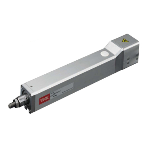
THK PCT User manual

INSTRUCTION MANUAL
PCT/PC
THK Electrical Actuator Press Series
No.369M Ver 3.00E
www.thk.ru
тел. +7(499) 703-39-86

Table of Contents
i
PCT/PC
1. Introduction 1-1
2. Safety Precautions 2-1
2-1 Warning indications on safety ______________________________________ 2-1
2-2 Safety Precautions _______________________________________________ 2-1
3. Structure and Mode 3-1
3-1 Structure and part names _________________________________________ 3-1
3-2 Model configuration ______________________________________________ 3-3
4. Storage and Transportation 4-1
4-1 Precautions to be observed for safe use_____________________________ 4-1
4-2 Precautions to be observed for prevention of fault,
fracture, or low performance of this product _________________________ 4-2
5. Installation and Operation 5-1
5-1 Precautions to be observed for safe use_____________________________ 5-1
5-2 Precautions to be observed for prevention of fault,
fracture, or low performance of this product _________________________ 5-2
5-3 Other precautions ________________________________________________ 5-3
5-4 Mounting method (PC) ____________________________________________ 5-4
5-5 Mounting method (PCT) ___________________________________________ 5-5
6. Maintenance 6-1
6-1 Precautions to be observed for safe use_____________________________ 6-1
6-2 Precautions to be observed for prevention of fault,
fracture, or low performance of this product _________________________ 6-1
6-3 Daily inspection __________________________________________________ 6-2
6-4 Periodical inspection______________________________________________ 6-2
6-5 Lubrication ______________________________________________________ 6-3
6-6 Method for supplying grease (PC) __________________________________ 6-4
6-7 Method for supplying grease (PCT) _________________________________ 6-6
7. Appendix 7-1
7-1 Motor mounting procedure (PCT) ___________________________________ 7-1
7-2 Replacement of timing belt procedure (PC) __________________________ 7-7
7-3 Replacement of timing belt procedure (PCT) ________________________7-11
7-4 Replacement of motor procedure (PCT) ____________________________7-14
7-5 Permissible input torque__________________________________________7-16
7-6 Permissible axial load ____________________________________________7-16
7-7 Introduction of the grease ________________________________________7-17
7-8 Introduction of the grease gun unit_________________________________7-19
www.thk.ru
тел. +7(499) 703-39-86

1. Introduction
1-1
PCT/PC
Thank you for purchasing the press series PCT/PC.
This product (PC) is the actuator that has achieved both small size and high thrust
force through the mechanism of integrating the ball screw nut and ball spline shaft.
This product (PCT) is a cylinder type electrical actuator using ball screws.
This manual describes the structure of the press series PCT/PC (main unit), and the
correct method for handling, installing and maintaining the product.
Carefully read and understand this manual before using the product, and then correctly
handle the product.
Store this manual after reading it so that it can be referred to at any time.
Reproduction or duplication of the whole or part of this manual without permission is
strictly prohibited.
Content of this manual is subject to change without notice.
This manual is available to download from our website. For the latest version, see
electrical actuator site (URL: https://tech.thk.com/).
We have made all possible efforts to make the content of this manual accurate.
However, if you find any mistake or uncertainty in this manual, please contact our
Customer Support.
Drawings in this manual show representative examples, and may differ from your
product.
This manual can be applied to special types. However, the descriptions defined in the
delivery specification documents or the delivery specification drawings of those special
types should take precedence over this manual.
1. Introduction
www.thk.ru
тел. +7(499) 703-39-86

2-1
2. Safety Precautions
PCT/PC
2-1 Warning indications on safety
This manual uses the following warning indications according to safety matters. The descriptions
next to warning indications on safety are important messages. Be sure to observe those
descriptions.
WARNING It indicates that erroneous handling may cause death or
serious injury to a person.
CAUTION It indicates that erroneous handling may cause injury to a
person or property damage only.
It indicates prohibitions (“don’t”).
It indicates obligations (“do”).
2. Safety Precautions
When you use this product in conjunction with Servo driver controller TLC or THC, read also the
instruction manual of TLC or THC.
2-2 Safety Precautions
This section describes important precautions that you must observe.
General
zWhile this product is operating or operable, for example, when the motor is energized,
do not enter the working area of any moving part.
Doing so may cause you to touch the moving part and injure you.
zWhile the motor is energized, do not move or install this product.
Doing so may cause electric shocks, or cause malfunction that could lead to injury.
zIf two or more people are involved in the installation or maintenance work, confirm the
procedure, signs and actions to cope with anomalies or the like in advance, and
separately appoint a person for monitoring the work.
Failure to do so may cause an unexpected accident.
WARNING
www.thk.ru
тел. +7(499) 703-39-86

2-2
2. Safety Precautions
PCT/PC
Transportation
zTo transport this product, hang the product at the specified position using a hanger (PC only).
Note: This hanging work must be carried out only by the qualified personnel wearing the protective
equipment such as helmets and safety shoes.
Doing so may cause the product to fall, leading to injury, or cause fault or fracture of the product.
* The hanger that comes with the product does not support the weight of any other products. When you
attach your devices or parts to this product, install a separate hanger.
* When hoisting the product, the body can incline due to the eccentricity of the center of gravity. Pay full
attention to this.
Installation and operation
zWire and connect the electric components correctly and securely.
Failure to do so may cause fire and electric shocks, or may cause abnormal operation that could lead to
injury, fault or fracture.
zBe sure to mount this product on a sufficiently strong base.
Fracture of a base may cause injury or damage to the machine.
zFirmly secure this product before operating it.
Failure to do so may cause abnormal operation that could cause injury, fault or fracture.
zIf any moving part may fall by its own weight in such events as breakage of a timing
belt, provide a safeguard for preventing the part from falling.
If any moving part falls, it may cause injury, fault or damage.
zWhile this product is operating, do not touch any moving part or rotating part.
Doing so may cause your hand to be caught and injured.
zDo not let the product operate with the cover, plug or grease lid removed.
Doing so may cause your body to be caught and injured.
Maintenance
zTurn off the machine (turning off power) before performing maintenance.
Failure to do so may cause electric shocks, or cause malfunction that could lead to injury.
WARNING
General
zDo not stand on this product or the packaging box.
Doing so may cause fault or damage. Or cause falling that could lead to injure.
zDo not impact this product.
Doing so may cause fault or damage. Or injure you.
zDo not disassemble or alter this product.
Doing so may cause fault due to entering of foreign material or adversely affect the performance or service
life. Or may cause abnormal operation that could lead to injury.
* If you wish to disassemble or alter the product, contact THK.
CAUTION
2. Safety Precautions
www.thk.ru
тел. +7(499) 703-39-86

2-3
2. Safety Precautions
PCT/PC
2. Safety Precautions
Unpacking
zBe careful not to hit your hands or body against protruded parts.
Doing so may injure you, or cause fault or fracture of the product.
zCheck whether the delivered product is the product you ordered.
Using a wrong product may cause malfunction that could lead to injury or fault.
* In the packaging box, an accuracy inspection report is attached.
zCheck whether the product has any fractured parts.
Using a fractured product may cause injury or fault.
* If you find any defect, contact our Sales Division.
Transportation
zDo not drop or hit this product.
Doing so may cause injury or fracture, or a functional loss.
zWhen transporting this product, do not hoist or hold any moving part or the cover.
Doing so may cause the product to fall, leading to injury, or cause fault or fracture of the product.
zWhen transporting this product, do not hoist or hold the motor, sensor or cable.
Doing so may cause the product to fall, leading to injury, or cause fault or fracture of the product.
zWhen hoisting this product, hold the external cylinder/housing/plate/flange part (for
PC) or base/motor bracket/flange part (for PCT). The models whose number is larger
than PC40-06B-0250 are heavy articles (20 kg or more). Two or more people should
hold the product as necessary.
Failure to do so may cause the product to fall, leading to injury, or cause fault or fracture of the product.
* For the weight of the product, see the catalog of press series PCT/PC.
Installation and operation
zFirmly secure this product before operating it.
Failure to do so may cause abnormal operation that could cause injury, fault or fracture.
zRemove the hanger and fixtures for moving part used for transportation before
operating this product.
Failure to do so may cause abnormal operation that could cause injury, fault or fracture.
zPay attention to avoid applying the tension or bending to cables.
Failure to do so may cause abnormal operation that could cause injury, fault or fracture.
zIf anomaly occurs, immediately stop the machine.
Failure to do so may cause abnormal operation that could cause injury, fault or fracture.
zDo not exceed the maximum speed when using the product.
Doing so may cause fault or damage. Or may cause abnormal operation that could lead to injury.
zDo not exceed the torque limit when using the product.
Doing so may cause fault or damage. Or may cause abnormal operation that could lead to injury.
* See “7. Appendix (p.7-16).”
zDo not apply a load that exceeds the permissible level.
Doing so may cause fault or damage. Or may cause abnormal operation that could lead to injury.
* See “7. Appendix (p.7-16).”
zDo not use the failed and broken product.
Doing so may cause injury or machine failure.
zAfter trial run, supply the specified grease to ball spline (only for PC) and ball screw
before using the product.
PC Design Symbol A (standard model) contains THK L500 grease.
PCT (standard product) contains THK AFB-LF grease.
CAUTION
www.thk.ru
тел. +7(499) 703-39-86

3. Structure and Mode
3-1
PCT/PC
3-1 Structure and part names
Fig. 1-1 shows the structure and part names of PC.
Hexagonal
post
Tension adjustment bolt
Motor bracket
Motor
Ball spline nut
Ball screw shaft
Stopper Plug
Housing
External
cylinder
Retainer
Flange
Rod
(Ball spline shaft
also serving as
a ball screw nut)
Grease nipple
Grease nipple
Eyebolt
Pulley
Pulley
Mecha lock
Mecha lock
Cover
Plate
Timing belt
Fig. 1-1 The structure and part names of press series PC
* Such parts as motor, driver, power cable between motor and driver, encoder cable and brake
cable (each cable is 5 m) come with the product. For the cable model (manufacturer), see the
catalog of press series PCT/PC. For the details of cables, contact the manufacturers.
* When you use PC30 or PC40 in combination with Servo driver controller THC, you can select the
cable length between motor and THC from 3 m, 5 m and 10 m.
* Eyebolt and hexagonal post are accessories. Remove them before use.
* For details such as the dimensions and accuracy, see the delivery specification drawings or
catalog of press series PCT/PC.
* For the details of Servo driver controller THC, see the instruction manual.
If you have any question, contact THK.
3. Structure and Mode
www.thk.ru
тел. +7(499) 703-39-86

3. Structure and Mode
3-2
PCT/PC
Fig. 1-2 shows the structure and part names of PCT.
Motor bracket
Grease lid Linear bush
Stopper
Rod
Ball screw
Steady rest
Angular bearing
Lock nut
Base
Flange
Head bolt
Stopper
Cover
Motor
Coupling
Fig. 1-2-a Press series PCT structure and part names (direct motor coupling)
Pulley A
Pulley B
Belt
Pulley plate
Pulley cover
Motor bracket
Motor
Fig. 1-2-b Press series PCT structure and part names (motor return)
* When you use the product in combination with Servo driver controller TLC or THC, you can
select the cable length between the motor and TLC/THC from 3 m, 5 m and 10 m.
* For details such as the dimensions and accuracy, see the delivery specification drawings or
catalog of press series PCT/PC.
* For the details of Servo driver controller TLC and THC, see the instruction manual.
If you have any question, contact THK.
3. Structure and Mode
www.thk.ru
тел. +7(499) 703-39-86

3. Structure and Mode
3-3
PCT/PC
3-2 Model configuration
PCT/PC model configuration (Combination of Servo Driver Controller TLC/THC)
The following is an example of model configuration.
PC30 - 06A - 0200 A - R - TH - R / M40B D00 D2 F3
② ③ ⑤④① ⑧⑦⑥ ⑩ ⑪⑨
①Model number ⑦Motor cable orientation
②Lead, reduction ratio ⑧Motor rated output
③Stroke (0100: 100 mm) ⑨Zero point method
④Design symbol ⑩Power supply voltage
⑤Option ⑪Cable type and length
⑥Control device
* For details, see the catalog of press series PCT/PC.
PC model configuration (Combination of motor and driver)
The following is an example of model configuration.
PC40 - 06A - 0050 A - D - M040B - U
② ③ ⑤④① ⑥ ⑦
①Model number ⑤Greasing position
②Lead, reduction ratio ⑥Applicable motor (control device)
③Stroke (0100: 100 mm) ⑦Motor cable orientation
④Design symbol
* For details, see the catalog of press series PCT/PC.
PCT model configuration (without motor type)
The following is an example of model configuration.
PCT20R - 06N - 0200 - R - 0 - A1- D
②① ③ ④ ⑤ ⑦⑥
①Model number ④Option
②Lead, reduction ratio ⑤With/without motor
③Stroke (0100: 100 mm) ⑥Motor bracket
⑦Method of fixing motor shaft
* For details, see the catalog of press series PCT/PC.
3. Structure and Mode
www.thk.ru
тел. +7(499) 703-39-86

4. Storage and
Transportation
4-1
PCT/PC
4-1 Precautions to be observed for safe use
4. Storage and Transportation
WARNING
CAUTION
zTo transport this product, hang the product at the specified position using a hanger.
Note: This hanging work must be carried out only by the qualified personnel wearing the protective
equipment such as helmets and safety shoes.
Doing so may cause the product to fall, leading to injury, or cause fault or fracture of the product.
* The hanger that comes with the product does not support the weight of any other products. When you
attach your devices or parts to this product, install a separate hanger.
* When hoisting the product, the body can incline due to the eccentricity of the center of gravity. Pay full
attention to this.
zDo not drop or hit this product.
Doing so may cause injury or fracture, or a functional loss.
zWhen transporting this product, do not hoist or hold any moving part.
Doing so may cause the product to fall, leading to injury, or cause fault or fracture of the product.
zWhen transporting this product, do not hoist or hold the motor, sensor or cable.
Doing so may cause the product to fall, leading to injury, or cause fault or fracture of the product.
zWhen hoisting this product, hold the external cylinder/housing/plate/flange part (for
PC) or base/motor bracket/flange part (for PCT). The models whose number is larger
than PC40-06B-0250 are heavy articles (20 kg or more). Two or more people should
hold the product as necessary.
Failure to do so may cause the product to fall, leading to injury, or cause fault or fracture of the product.
* For the weight of the product, see the catalog of press series PCT/PC.
www.thk.ru
тел. +7(499) 703-39-86

4. Storage and
Transportation
4-2
PCT/PC
4-2 Precautions to be observed for prevention of fault,
fracture, or low performance of this product
4. Storage and Transportation
zSince using in an adverse storage environment may cause fault or degradation, store
the product in the environment described below:
• Place at ambient temperature and humidity within the following storage temperature and humidity ranges
Storage temperature: 0°C to 60°C (no freezing)
Storage humidity: 20% RH to 80% RH (no condensation)
* With the product unpacked
• Place with no sudden temperature change
• Place with non-corrosive gas nor flammable gas
• Place with little dust, salt or metallic powder
• Place where water, oil or chemical can not contact the product
• Place where no direct sunlight nor radiation heat reaches
• Place where no strong electric field nor strong magnetic field develops
• Place where a vibration or shock does not transmit to the main unit
zWhen storing this product, enclose it in a package designated by THK and store it in a
horizontal orientation while avoiding high temperature, low temperature and high
humidity.
zDo not apply an excessive load on the package, since doing so may cause fault or
fracture.
www.thk.ru
тел. +7(499) 703-39-86

5. Installation and
Operation
5-1
PCT/PC
5-1 Precautions to be observed for safe use
zWire and connect the electric components correctly and securely.
Failure to do so may cause fire and electric shocks, or may cause malfunction that could lead to injury, fault or
fracture.
zBe sure to mount this product on a sufficiently strong base.
Fracture of a base may cause injury or damage to the machine.
zFirmly secure this product before operating it.
Failure to do so may cause abnormal operation that could cause injury, fault or fracture.
zIf any moving part may fall by its own weight in such events as breakage of a timing belt,
provide a safeguard for preventing the part from falling.
If any moving part falls, it may cause injury, fault or damage.
zWhile this product is operating, do not touch any moving part or rotating part.
Doing so may cause your hand to be caught and injured.
zDo not let the product operate with the cover, plug or grease lid removed.
Doing so may cause your body to be caught and injured.
zPay attention to avoid applying the tension or bending to cables.
Failure to do so may cause abnormal operation that could cause injury, fault or fracture.
zIf anomaly occurs, immediately stop the machine.
Failure to do so may cause abnormal operation that could cause injury, fault or fracture.
zDo not exceed the maximum speed when using the product.
Doing so may cause fault or damage. Or may cause abnormal operation that could lead to injury.
zDo not exceed the torque limit when using the product.
Doing so may cause fault or damage. Or may cause abnormal operation that could lead to injury.
* See “7. Appendix (p.7-16).”
zDo not apply a load that exceeds the permissible level.
Doing so may cause fault or damage. Or may cause abnormal operation that could lead to injury.
* See “7. Appendix (p.7-16).”
zDo not use the failed and broken product.
Doing so may cause injury or machine failure.
zDo not use the product with applying radial load and moment load to the rod part.
Doing so may cause fault or damage. Or may cause abnormal operation that could lead to injury.
5. Installation and Operation
WARNING
CAUTION
www.thk.ru
тел. +7(499) 703-39-86

5. Installation and
Operation
5-2
PCT/PC
5-2 Precautions to be observed for prevention of fault,
fracture, or low performance of this product
zSince using in an adverse service environment may cause fault, use the product in the
environment described below.
• Place at the following operating temperature (humidity) range
Operating temperature: 0°C to 40°C
(Ambient humidity: 20% RH to 80% RH, no freezing or condensation)
* If you desire to use the product in a special environment or outside of the operating temperature range,
contact THK.
• Place with no sudden temperature change
• Place with non-corrosive gas nor flammable gas
• Place with no floating of dust, salt or metallic powder
• Place where water, oil or chemical can not contact the product
• Place where no direct sunlight, ultraviolet rays, nor radiation heat reaches
• Place where no strong electric field nor strong magnetic field develops
• Place where a vibration or shock does not transmit to the main unit
zPrevent foreign material such as dust or metallic powder from entering the product
since it may cause abnormal wear or shorten the service life.
If foreign material may enter the product, take a dustproof measure that matches the service
atmosphere.
zUse the product within the effective stroke range.
zBe sure to mount this product on a sufficiently rigid base. In addition, the mounting
surface must be a machined plane or have accuracy equivalent to the machined plane.
zCheck that there is no tool or bolt in the product before operating it.
zAfter trial run, supply the specified grease to ball spline (only PC) and ball screw before
using the product.
PC Design Symbol A (standard model) contains THK L500 grease.
PCT (standard product) contains THK AFB-LF grease.
zWhile PC is provided with a rod retainer inside the product, provide a separate stopper
outside of the device to prevent the rod from colliding with the retainer. Or you may
provide a separate sensor outside of the device as necessary to prevent the collision.
zWhen performing the pressing origin return with the load side detecting system, please
limit the speed and torque before operation.
5. Installation and Operation
www.thk.ru
тел. +7(499) 703-39-86

5. Installation and
Operation
5-3
PCT/PC
5. Installation and Operation
5-3 Other precautions
zAdjust the parameter and gain of the driver according to the usage conditions.
* For Servo driver controller TLC and THC, parameters are configured for each actuator.
Depending upon the usage conditions, it may be necessary to adjust the parameters such as
gain.
zFor handling of a motor and a driver, see the respective catalog and instruction
manual issued by the motor and driver manufacturers.
* For the details of Servo driver TLC and THC, see the instruction manual.
zFor handling and mounting of a timing belt, see the respective catalog issued by the
timing belt manufacturer.
* For models of standard timing belts, see Table 1-1, 1-2 and 1-3.
Model number Timing belt model
PC30-06A 340-EV5GT-9
PC40-06B 400-EV5GT-9
PC40H-08C 560-EV8YU-15
PC50-06D 560-EV8YU-15
PC60-10E 704-EV8YU-20
PC60H-10F 720-EV8YU-25
PC80L-12G 984-EV8YU-40
PC80-12G 984-EV8YU-40
PC80H-12G 984-EV8YU-40
Table 1-1 Models of Standard Timing Belts Design Symbol A (Gates Unitta Asia Company)
Model number Motor capacity Timing belt model
PCT20R 50 W 196-2GT-6
PCT25R 100 W 273-3GT-6
200 W 273-3GT-9
Table 1-2 Models of Standard Timing Belts (Gates Unitta Asia Company)
www.thk.ru
тел. +7(499) 703-39-86

5. Installation and
Operation
5-4
PCT/PC
5. Installation and Operation
5-4 Mounting method (PC)
Fix this product to the mounting surface using hexagonal-socket-head type bolt (tensile strength
rank 10.9 or higher) through the mounting hole of flange. See Fig. 2-1. Also see Table 2-1, which
shows the size and the recommended length of bolts for securing to flange.
Bolts for securing to flange
Fig. 2-1 Drawing for mounting to flange
Model number Bolt Size Recommended
bolt length
Mounting surface
Recommended
female thread depth
Plate
thickness
dimension of
flange
PC30-06A M6 25 mm or larger 12 mm or larger 14 mm
PC40-06B
PC40H-08C M8 25 mm or larger 16 mm or larger 14 mm
PC50-06D M10 35 mm or larger 20 mm or larger 18 mm
PC60-10E
PC60H-10F M12 40 mm or larger 24 mm or larger 20 mm
PC80L-12G
PC80-12G
PC80H-12G
M16 55 mm or more 32 mm or more 30mm
Table 2-1 Flange Securing Bolt Size and Recommended Length
Mounting procedure
Mount this product in the following procedure:
①Confirm that there is no burr, dent or dust on the surface you mounted.
If there is any burr or scratch, remove it with an oilstone or the like. Also, remove dust with a
clean waste cloth or the like.
②Likewise, confirm that there is no burrs, scratches or dust on the flange of PC, and remove
them as necessary.
③Mount PC on the mounting surface. When mounting, use the dedicated hanger as
necessary.
④Adjust the position so that the center of the mounting hole of PC’s flange and that of the
screw hole of the mounting surface match.
⑤Using the recommended bolt listed on Table 2, apply temporary fastening.
⑥Using a torque wrench, fasten the bolts. The material of flange is SS400.
www.thk.ru
тел. +7(499) 703-39-86

5. Installation and
Operation
5-5
PCT/PC
5. Installation and Operation
5-5 Mounting method (PCT)
Fix this product using hexagonal-socket-head type bolt (tensile strength rank 10.9 or higher)
through the holes for securing flange or through T slots on the side surface of the unit base with
square nuts (attached to the product). See Fig. 2-2-a and b. Also see Table 2-2, which shows the
size and the recommended length of bolts for securing to flange.
Bolts for securing to flange
Fig. 2-2-a Drawing for mounting to flange
* Optimal bolt
length
* Bolt is too short,
easy to loosen.
Square nuts for securing to T slots
(Attached to the product) Bolts for securing to T slots
* Bolt is too long,
with backlash.
Fig. 2-2-b Drawing for mounting to T slots
www.thk.ru
тел. +7(499) 703-39-86

5. Installation and
Operation
5-6
PCT/PC
5. Installation and Operation
Model
number
Mounting
method
Bolt
Size
Bolt
Quantity
Recommended
bolt length
Mounting surface
Recommended
female thread
depth
Plate thickness
dimension of
flange
PCT20 flange M5 4 18 mm 10 mm or larger 10 mm
T slot M3 8 - - -
PCT25 flange M6 4 25 mm 12 mm or larger 15 mm
T slot M4 8 - - -
Table 2-2 Securing Bolt Size and Recommended Length
Mounting procedure
Mount this product in the following procedure:
①Confirm that there is no burr, dent or dust on the surface you mounted.
If there is any burr or scratch, remove it with an oilstone or the like. Also, remove dust with a
clean waste cloth or the like.
②Likewise, confirm that there is no burr, dent or dust on the mounting surface of PCT, and
remove it as necessary.
③Mount PCT on the mounting surface.
④Adjust the PCT position.
⑤Using the recommended bolt listed on Table 2, apply temporary fastening.
⑥Using a torque wrench, fasten the bolts. The material of the flange is AC4A, and the material
of the base is A6063S-T5.
www.thk.ru
тел. +7(499) 703-39-86

6-1
PCT/PC
6. Maintenance
6-1 Precautions to be observed for safe use
6-2 Precautions to be observed for prevention of fault,
fracture, or low performance of this product
zTurn off the machine (turning off power) before performing maintenance.
Failure to do so may cause electric shocks, or cause malfunction that could lead to injury.
zIf two or more people are involved in the maintenance work, confirm the procedure,
signs and actions to cope with anomalies or the like in advance, and separately appoint a
person for monitoring the work.
Failure to do so may cause an unexpected accident.
zWhen handling grease, wear protective glasses and protective gloves.
If grease gets into eyes or touch the skin, it may affect your body such as causing inflammation.
* If grease gets into eyes, clean them with clean water for 15 minutes and visit the doctor.
* If grease touches skin, wash it sufficiently with water and soap.
zAfter greasing, travel the block back and forth throughout, and wipe off the surplus
grease.
If you restart operation immediately after greasing, the surplus grease flies and may cause faults and affect
your body.
zDo not apply grease to a flame, a firework or a high-temperature object.
Doing so may ignite the grease, which could cause fire.
* For other information on handling grease, see the precautions indicated on the grease package or catalog.
We have “Safety Data Sheets” for THK original greases. Contact THK for details.
zTo have this product fully exerts its functions, it is essential to lubricate the product. Be
sure to supply grease on a regular basis.
Using the product with insufficient lubrication may shorten the service life.
zDo not to let foreign material enter the ball spline, linear bush or ball screw.
Doing so may cause fault, or could adversely affect the performance or service life.
zDo not mix greases of different types.
Doing so may affect the performance.
WARNING
CAUTION
6. Maintenance
www.thk.ru
тел. +7(499) 703-39-86

6-2
PCT/PC
6. Maintenance
6-3 Daily inspection
6-4 Periodical inspection
zBefore operating the product, visually check any exterior damage or stain.
zCheck the grease state on the rod (stain, etc.). If the grease is significantly stained, wipe
off the grease, and then supply new grease.
zCheck whether abnormal noise or vibration occurs during operation. If abnormal noise or
vibration occurs, immediately stop the machine and inspect the state of the product.
Insufficient lubrication or loosened mounting bolts may cause abnormal noise or vibration.
zFor the products including timing belts (wrap-around motor-type), we recommend
adjusting the belt tension after about a month of operation.
• Initial elongation of the belt may lower the belt tension.
zPerform more detailed inspection approximately once every 3 to 6 months.
• Check the lubrication state, and then clean the product and replenish the grease as necessary.
• Inspect whether the mounting bolts are loosened, and retighten it as necessary.
• Check the timing belt state (wear, scratch, crack, noise, etc.). When any anomaly (abnormal wear, scratch,
crack, etc.) is found, replace the timing belt.
* See the appendix “Replacement of timing belt procedure.”
6. Maintenance
www.thk.ru
тел. +7(499) 703-39-86

6-3
PCT/PC
6. Maintenance
6-5 Lubrication
zAfter trial run, supply the specified grease to ball spline (only for PC) and ball screw
before using the product.
PC Design Symbol A (standard model) contains THK L500 grease.
PCT (standard product) contains THK AFB-LF.
zFor the greasing interval, if normal operation that pressure is applied at one end of
stroke, replenish grease approximately every 500 km travel distance or 6 months,
whichever is earlier.
However, note that the greasing interval varies with the service conditions or service environment. We
recommend determining the greasing interval through the initial inspection.
* See "Method for supplying grease" on next page.
6. Maintenance
Model Amount of filled grease [cc]
Ball screw part Ball spline part Bearing part
PC30-06A 1.6 2.5 10
PC40-06B 3.3 61.45
PC40H-08C 6.2 62.17
PC50-06D 9.5 10 2.17
PC60-10E 17.1 20 4.4
PC60H-10F 24 20 6.6
PC80L-12G 40 35 18.9
PC80-12G 40 35 18.9
PC80H-12G 40 35 18.9
Table 3-1 Amount of greasing Design Symbol A (standard)
Model Amount of filled grease [cc]
Ball screw lead [mm] Ball screw part
PCT20 6 0.1 + 0.1 x (Effective stroke/50)
PCT25 4 0.6 + +0.4 x (Effective stroke/50)
6 0.5 + +0.3 x (Effective stroke/50)
Table 3-2 Amount of greasing (standard)
www.thk.ru
тел. +7(499) 703-39-86
This manual suits for next models
12
Table of contents
Other THK Controllers manuals
