SICHERHEITSVORSCHRIFTEN: LESEN SIE DIESE BETRIEBSANLEITUNG vor der Installation dieses Produktes.
WARNUNG: GEFAHR EINES ELEKTRISCHEN SCHLAGES.
Die Installation dieser Pumpe darf nur von fachkundigen Technikern übernommen werden.
Es ist empfehlenswert diese Anleitung aufzubewaren da wichtige Informationen über Sicherheit und korrekte Installation enthalten sind.
Alle elektrischen Anschlüsse nur von kompetenten Fachleuten durchführen . Alle elektrischen Anschlüsse müssen mit den Nationalen und Lokalen
elektrischen Codes übereinstimmen.
Dieses Produkt erfüllt die Europäische Normen der Low Voltage Safety, und enthält Komponente die mit der europäischen EMC Norm
übereinstimmen.
Sicherstellen, dass die Pumpe von dem elektrischen Anschluss ausgeschaltet ist bevor ein Eingriff oder Service unternommen wird.
Das Mittel der Isolierung muss gemäss Verkablungs Vorschriften so aufgenommen werden dass die Verkablung in Uebereinstimmung mit den
Nationalen Vorschriften ist.
Das Netzkabel kann nicht ersetzt werden. Wenn das Kabel beschädigt ist sollte die Pumpe ersetzt werden.
Es ist keine Tauchpumpe. Diese Pumpe ist nicht geeignet für die Anwendung in Schwimmbäder oder Marine Anwendungen. Diese Pumpe sollte nur
mit sauberem Kondensatwasser benutzt werden..
Diese Pumpe ist für den Innenbereich an einem trockenen Ort bestimmt.
Die Pumpen Front Hülle muss richtig aufgesetzt werden nach einer Installation oder Service.
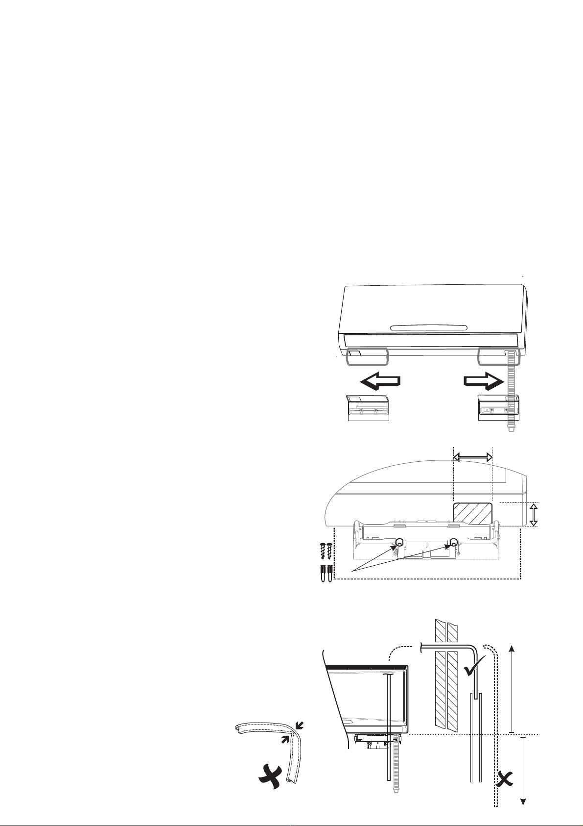
Installation
Position
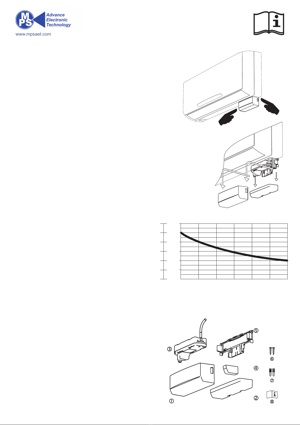
Bestimmen Sie die beste Position um den
Drainagesschlauch auf die Höhe der Halterung bringen
und von dem Gebrauch der vorgegebenen Löcher
machen.
Dazu können Sie die vorhandene Schablone gebrauchen.
Lassen Sie 3 cm Luft (Platz) für den Zugriff beim Service.
Cut-out
Fixierung
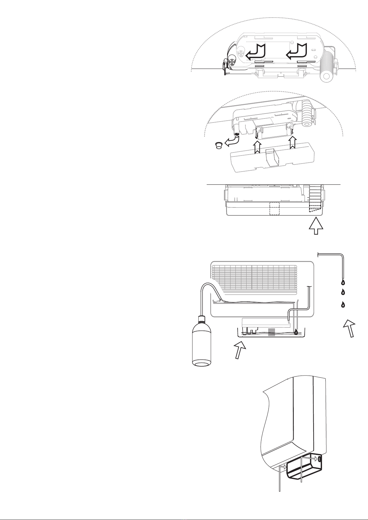
Entfernen Sie die Abdeckung vom Drainageaussgang des
Klimagerätes und benützen Sie die Verpackungs
Schablone für die Markierung um die Wandplatte zu
fixieren.Die Pumpenwandplatte muss das Drainage-
ausgangsloch überlappen.
Lösen Sie das Material der Schablone”Ausgangdrainage”
um ein Loch von 58 x 42 mm Minimun zu bekommen.
Bohren sie die Löcher für die Fixierung der Wandplatte.
Die Schrauben und Wandbefestigung wird mitgeliefert.
Der Installateur sollte das geeignete fixierungs Material
gemäss der Wand Konstruktion benützen.
58 mm
42 mm
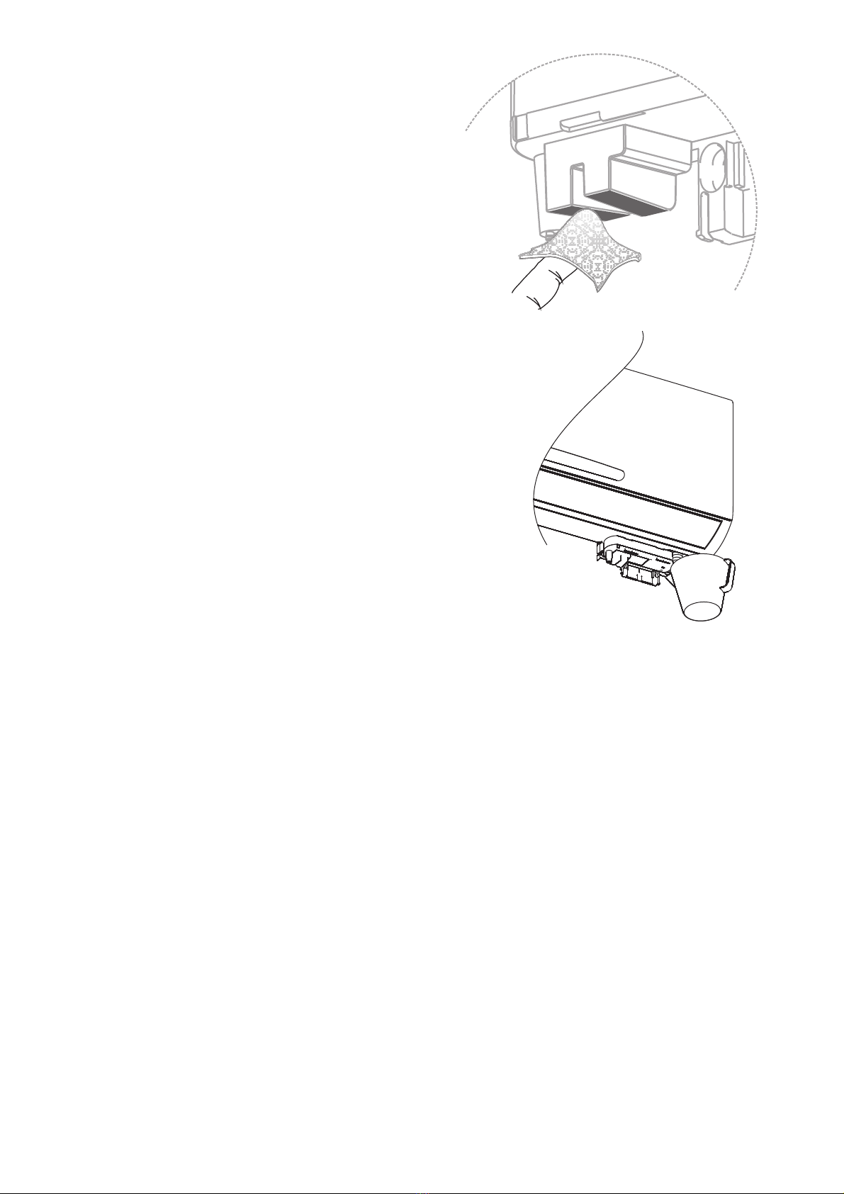
Ablasschlauch
Ziehen Sie den Drainageschlauch runter.
Positsionieren Sie den Ablasschlauch und führen Sie ihn zum
geeigneten Abfluss.Beachten Sie dass keine Kondensatwasser
Abfluss Behinderungen vorhanden sind.
Vermeiden Sie einen Siffoneffekt der¨einen unnötigen Lärm
produzieren kann.
6 m max.