MS Sedco DH100-CT User manual

DH100-CT
Sliding Pedestrian Door Motion & Presence Sensor INSTALLATION INSTRUCTIONS
Page 1
(/MANU) DH100-CTv1017
Section 1
General Description
The DH100-CT is an active infrared presence sensor that
is designed to provide both activation and safety
detection for automatic sliding and folding doors in a
single device.
• Test Input provides sensor monitoring
capabilities as required by the latest
industry standard.
• Pattern depth and width are
adjustable using mounting height,
dip switches, detection area depth,
and detection area width adjustments.
• Frequency can be changed to prevent interference
from other sensors in close proximity.
• Self-Diagnostic means the sensor continuously
monitors itself.
• Monitor Mode Switch ensures against false operation
caused by snow, leaves, insects, etc.
• Programmable Presence Timer (2 sec., 30 sec.,
60 sec., or infinity).
Section 2
Parts Identification
Section 3
Mounting Information
1. Do not mount higher than 9.84 ft. (3m).
2. Mount within 50mm (1.97”) from bottom of header
cover.
3. Do not leave any objects which may move in the
detection pattern.
4. Avoid steamy environments.
5. Ensure rain or snow will not fall directly on unit.
6. Ensure snow or water can not accumulate on floor.
7. Ensure a minimum of reflected sunlight from the
floor.
8. Use different frequency settings for sensors in close
proximity.
Accessories
Use Alternate Frequency.
132
34
5
6
A B
7
NOTE: Set up for this sensor should be
performed by an AAADM-certified installer.
7898 Zionsville Road Indianapolis, Indiana 46268
Telephone: (317) 842-2545 www.mssedco.com custsvc@mssedco.com
To maximize the effectiveness of doorway detection,
install the DH100-CT outside and inside as shown
below.
A B
Side ViewPlan View
Moving Door Leaf Moving Door Leaf
A
B
Max 50mm
3.0m
(9.84ft)
Cover
Indicator LED
(Red, Green &Blue)
Base
Area Mask
(Inner 3Rows)
Area Mask
(Outer 2Rows)
Detection Window
Potentiometer
(Sensitivity Volume)
Connector
Depth Adjustment
Lever Arm
(Inner 3 Rows)
Depth Adjustment
Lever Arm
(Outer 2 Rows)
Dip Switch
Dip Switch
X
Y
Installation
Instruction
Mounting Template
Cable
Mounting Screws
(2 pcs.)
(1.97”)

Section 4
Mounting and Wiring
1. Using the mounting template
provided, drill mounting and
wire holes.
2. If you need to remove the sensor body from its base,
lift the sensor body from the base and tilt it forward
to remove as
illustrated.
3. Fasten unit with mounting screws provided.
4. When wiring to a door controller that can test the
sensor, set “Test input” dip switch setting 6 to
“ON”.
5. When wiring to a door controller that cannot test the
sensor, set “Test input” dip switch setting 6 to
“OFF”.
6. House connector in receptacle.
7. Replace cover.
NOTE: Be careful not to inadvertently move
the Depth Adjustment Lever Arms when
replacing the cover.
Section 5
Dip Switch Settings
Presence Timer: The sensor will detect a stationary
object for the preset Presence Timer Setting on the inner
3 rows.
Number of Rows: The number of active rows can be set
to 5, 4, 3 or 2 depending on detection area requirements.
Frequency: When more than two sensors are used in
close proximity to each other select different frequency
settings for each sensor to prevent interference.
Safety Relay Output: Refer to Timing Chart of events for
full details on Safety Output.
Reflection Diagnostics: A low reflected infrared signal is
indicated by a slow flashing Red/Green LED. To ignore
this low reflection “Low Reflection” (ON).
: Default Setting
Page 2
(/MANU) DH100-CTv1017
DH100-CT
Sliding Pedestrian Door Motion & Presence Sensor INSTALLATION INSTRUCTIONS
7898 Zionsville Road Indianapolis, Indiana 46268
Telephone: (317) 842-2545 www.mssedco.com custsvc@mssedco.com
Depth Adjustment
Lever Arm
!
ON
Dip Switch X
1 2 3 4 5 6 7 8
2s
1 2
30s
1 2 1 2 1 2
60s ∞
3Rows ON 2Rows ON
4Rows ON
5Rows ON
R5
3 4
R4
3 4
R3
3 4
R2
3 4
A
5 6
B
5 6 5 6 5 6
C D
N.O.
N.C.
Safety Output (Opto-Coupler)
7
N.O.
N.C.
Transmitter Receiver
IR Spot
Receiver
IR Spot
Transmitter
LED
Low Ref.
88
Normal
Sensor’s
Cable Cable
Red
Black
White
Green
Yellow(+)
Blue(-)
Gray(+)
R2,3,4,5
Output
AC/DC
12 to 24 [V]
±10%
R1,2
Output
Collector
Emitter
N.O.
COM
Power
(Non Pole)
ON 6
OFF
Y
do not connect
do not connect
Brown(-)
Sensor’s
Cable Cable
Red
Black
White
Green
Yellow(+)
Gray(+)
R2,3,4,5
Output
AC/DC
12 to 24 [V]
±10%
R1,2
Output
Collector
Emitter
N.O.
COM
Power
(Non Pole)
Test Input
Test-P
Test-N
ON 6
OFF
Y
Blue(-)
Brown(-)
1
1
2
50mm

Direction Detection: When set to ON, pedestrians
Moving away from the sensor will not be detected.
NOTE: For pedestrian safety
purposes when “Doorway Learn” is set to ON, the
1st and 2nd row of detection will detect
pedestrians regardless of direction of movement.
Activation Relay Output: Refer to Timing Chart of events
for full details on Activation Output.
Monitor Mode: Snow mode should only be used in
exterior environments where heavy snow or other extreme
conditions exist.
Door Hold: Switch to OPEN to hold the door in the open
position.
Doorway Learn: Doorway Learn allows the 1st row of
detection to be focused inside the door close area
without detecting the door movement.
NOTE: When Doorway Learn is turned ON, the
sensitivity level of the inner row of detection is
only at maximum when the outer rows of
detection are activated.
Test Input Setting from Door Controller: When
connected to a door controller without a TEST input, set
to “OFF”. When connected to a door controller with a
TEST input, set to “ON”. Refer to Timing Chart of events.
: Default Setting
Section 6
Power
BEFORE APPLYING POWER, READ AND FOLLOW THESE
INSTRUCTIONS:
When power is applied, the sensor will read and store the
environmental optical parameters. This is necessary for
Presence Detection to work properly.
1. CLEAR THE AREA OF ANY UNNECESSARY OBJECTS.
2. Apply POWER.
3. Vacate the Detection Pattern immediately. While the
sensor sees ANY moving objects in its DETECTION
PATTERN, it will not proceed to the following step.
4. DO NOT enter DETECTION PATTERN for 10 seconds
(Presence Detection Setting).
5. TEST the presence feature, especially near the door.
When carrying out the following work, TURN OFF THE
POWER:
1. When the floor conditions change.
2. Adjusting pattern or sensitivity.
“DOORWAY LEARN” is OFF
(Ref. Sec. 5-Dip Switch Settings)
•Upon power ON, the solid Green LED turns on
indicating that the sensor is in standby mode and
ready to detect.
Page 3
(/MANU) DH100-CTv1017
Sliding Pedestrian Door Motion & Presence Sensor INSTALLATION INSTRUCTIONS
DH100-CT
7898 Zionsville Road Indianapolis, Indiana 46268
Telephone: (317) 842-2545 www.mssedco.com custsvc@mssedco.com
!
!
Green solid LED
Dip Switch Y
ON
1 2 3 4 5 6
ON
11
OFF
N.O.
N.C.
2
Activation Output (Mechanical Relay)
Snow
33
Normal
Open
44
Auto
Door
OFF ON
55
Door
OFF
ON
6
0v
ON
Without TEST
With TEST
Without TEST
0v
OFF
Y5

Page 4
(/MANU) DH100-CTv1017
Sliding Pedestrian Door Motion & Presence Sensor INSTALLATION INSTRUCTIONS
DH100-CT
7898 Zionsville Road Indianapolis, Indiana 46268
Telephone: (317) 842-2545 www.mssedco.com custsvc@mssedco.com
Presence Detection: It takes 10 seconds after the
sensor powers up for presence detection to be initiated
on all rows of detection. If someone enters the detection
area before 10 seconds has elapsed, the sensor will
continue to initialize until after 5 seconds with no motion
being detected.
“DOORWAY LEARN” is ON
(Ref. Sec. 5-Dip Switch Settings)
•Upon power ON, the Red LED indicates a door open
relay output to begin the “Doorway Learn” process.
•Green LED blinks for about 10 seconds as “Doorway
Learn” process is carried out. Door opens/closes.
•After the “Doorway Learn” process is completed,
sensor is in standby mode.
Presence Detection: During the “Doorway Learn”
process, the outer 4 rows of detection on the DH100-CT
sensor switch from motion detection to presence
detection 10 seconds after power ON. The inner
“Doorway Learn” row of detection will switch from motion
to presence detection after the “Doorway Learn” process
is complete.
“Doorway Learn” Failure & Recovery: If a person enters
the detection area during the “Doorway Learn” process, it
may not be successfully completed. In this case, the
sensor will carry out the “Doorway Learn” process on
door activation caused by a person in order to build an
accurate image of the door open and door close position.
NOTE: When “Doorway Learn” is turned ON, the
sensitivity level of the inner row of detection is at
maximum ONLY when the outer rows of detection are
activated.
CAUTION: When carrying out the following work,
turn off sensor power.
■When the floor condition is changed by placing
a mat on the floor, etc.
■When the detection area pattern or sensor
sensitivity is adjusted.
Red solid LED
Green blinking LED
Green blinking LED
Green solid LED
!
Y5

Section 7
Adjusting Detection Pattern
Detection Area Depth Adjustment: Inner 3 Rows
Detection Area Width Adjustment
Detection Area Depth Adjustment: Outer 2 Rows
Optical beams are designed as shown above.
Please note that actual detection area is
variable, depending on cloths, materials on the
floor and sensitivity adjustment. Please confirm
the actual area after adjustment.
Section 8
Door Maintenance Work
When carrying out door maintenance work with power
applied to the sensor, on door controllers that are wired
to “test” the sensor, ensure the dip switches are set as
shown below:
NOTE: Be sure to return the dip switch settings
to their original state once door maintenance
work is complete.
Page 5
(/MANU) DH100-CTv1017
!
!
Sliding Pedestrian Door Motion & Presence Sensor INSTALLATION INSTRUCTIONS
DH100-CT
7898 Zionsville Road Indianapolis, Indiana 46268
Telephone: (317) 842-2545 www.mssedco.com custsvc@mssedco.com
Inner 3
rows
adjustment
lever arm
Door
Door
[-8 degree] setting
[0 degree] setting
With
Base
(1.0m)
3.3’
(1.5m)
4.9’
(0.5m)
1.6’
(1.0m)
3.3’
(1.5m)
4.9’
(0.5m)
1.6’
3.3’ (1.0m)
6.6’ (2.0m)
7.2’ (2.2m)
9.8’ (3.0m)
(1.0m)
3.3’
Door Door
Without
Base
[-8 degree] setting
[0 degree] setting
(0.5m)
1.6’
(1.0m)
3.3’
(0.5m)
1.6’
3.3’ (1.0m)
6.6’ (2.0m)
7.2’ (2.2m)
9.8’ (3.0m)
Area Mask
(Inner 3Rows)
Area Mask
(Outer 2Rows)
0
Narrow
Wide
Width
Narrow
Wide
(1.0m)
3.3’
(2.0m)
6.6’
(1.0m)
3.3’
(2.0m)
6.6’
3.3’ (1.0m)
6.6’ (2.0m)
9.8’ (3.0m)
Outer 2 rows
adjustment
lever arm
[m]
[0 degree] setting
[m]
[0 degree] setting
0
[m]
[+10 degree] setting
0
[m]
[+10 degree] setting
With
Base
Without
Base
(1.0m)
3.3’
(2.0m)
6.6’
(1.0m)
3.3’
(2.0m)
6.6’
3.3’ (1.0m)
6.6’ (2.0m)
7.2’ (2.2m)
9.8’ (3.0m)
(1.0m)
3.3’
(2.0m)
6.6’
(1.0m)
3.3’
(2.0m)
6.6’
3.3’ (1.0m)
6.6’ (2.0m)
7.2’ (2.2m)
9.8’ (3.0m)
(3.0m)
9.8’
ON
12345678
Dip Switch X
2s
1 2
Low
Ref. 8

Section 9
Verification of Operation
1. After mounting, setting parameters and applying
power, walk test unit to verify detection pattern.
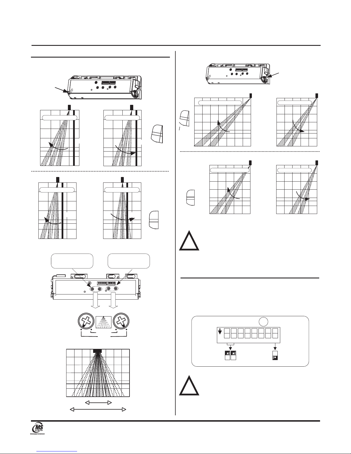
2. If the sensor does not function as expected, TURN
OFF THE POWER and RECHECK the Depth Adjustment
Lever Arms, Dip Switch and Width Mask Knobs as
described in Sections 5 and 7.
3. After rechecking, if there is still a problem, adjust the
sensitivity.
*****EXTREMELY IMPORTANT*****
After final set-up, test unit(s) completely to ensure that
proper coverage has been achieved (width, depth and
location of the pattern must be tested).
After the installation and operational check of the
system:
1. Place the proper labels on the door per all applicable
standards.
2. Instruct the owner of the door system operation and
how to test it. This should be checked on a daily
basis.
3. Instruct the owner on what to do if the door or any of
its components become damaged.
4. Strongly recommend to the owner that the complete
entry be inspected twice a year as part of the service
agreement.
Section 10
Self Diagnostics
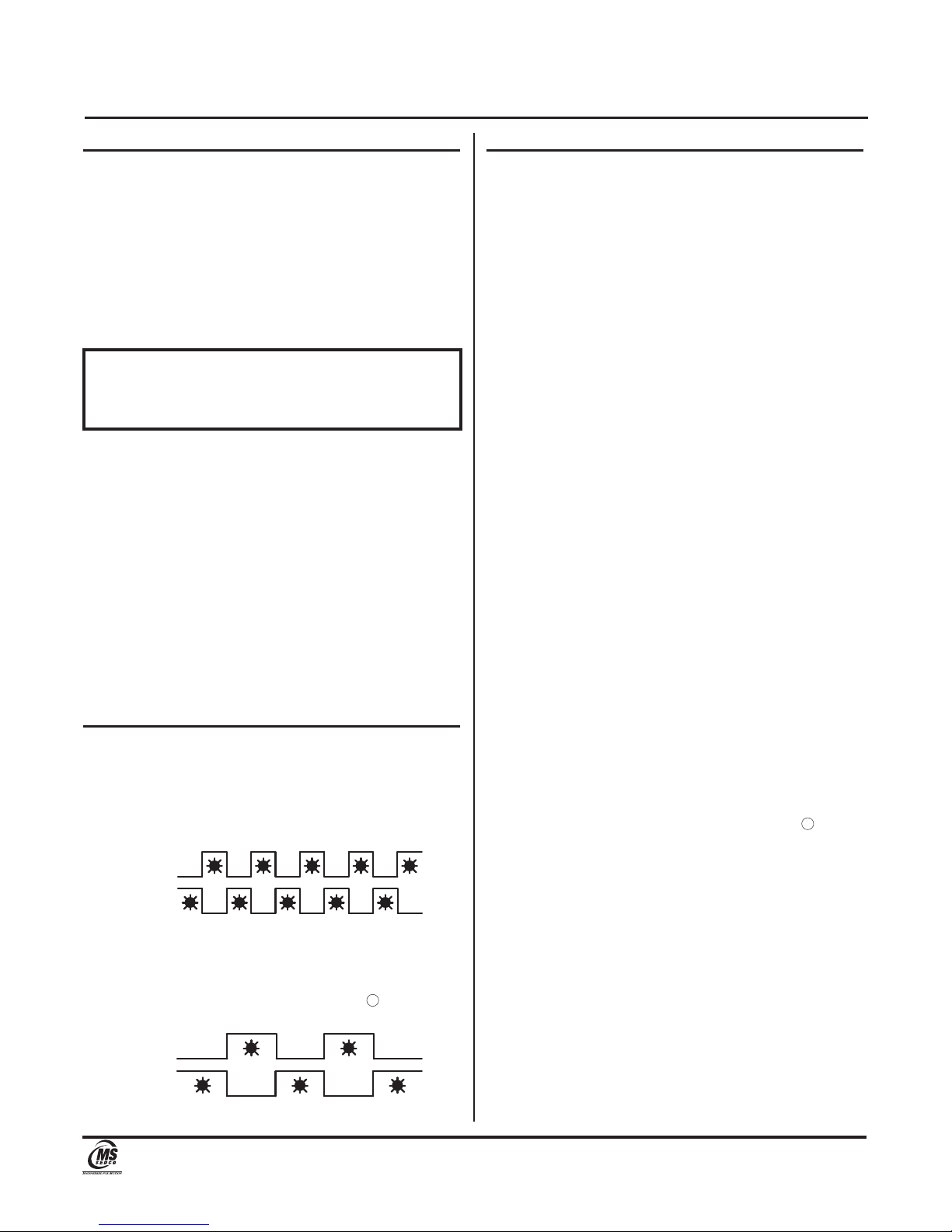
A flashing Green/Red LED inducates any technical issues
with the HR100-CT. The frequency of the flashing
indicates the type of issue as explained below:
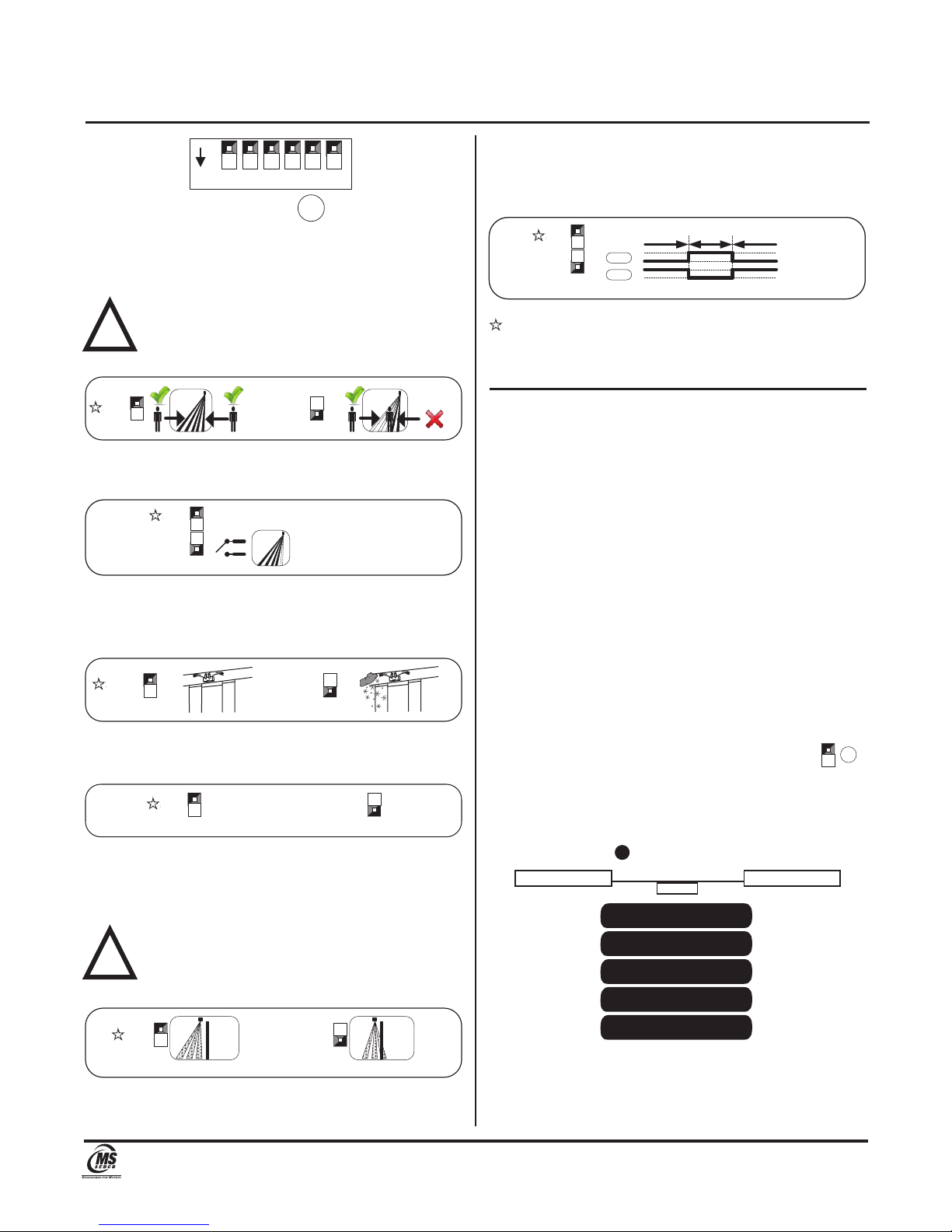
LEDs Flashing Fast = Please replace the sensor.
LEDs Flashing Slow = Confirm that sensitivity
potentiometer is set to maximum and re-power the
sensor. If the error persists, set Dip Switch 8 to “Low
Reflection”.
Section 11
Troubleshooting
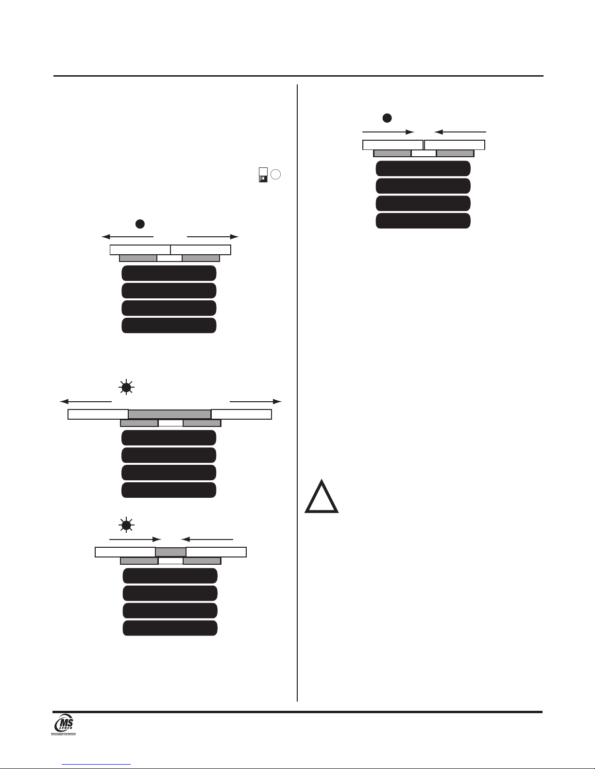
PROBLEM 1: Door does not open when person enters
the detection area.
LED STATUS: OFF
CAUSE 1: Sensor Connector.
SOLUTION 1: Tighten connector or reconnect.
CAUSE 2: Power Supply.
SOLUTION 2: Check that the power supply is properly
connected and 12V to 24V AC or DC.
CAUSE 3: Sensor Wiring.
SOLUTION 3: Double check sensor wiring is accurate.
PROBLEM 2: Door operates by itself (Ghosting).
LED STATUS: Door Opens RED,
Door Closes GREEN
CAUSE 1: Moving objects in detection area.
SOLUTION 1: Remove the moving object from the
detection area.
CAUSE 2: Sensitivity too high.
SOLUTION 2: Reduce sensor sensitivity.
CAUSE 3: Dust, frost or water droplet on the
sensor lens.
SOLUTION 3: Wipe the sensor lens clean and install a
weather cover if necessary.
CAUSE 4: Detection area overlaps with that of
another sensor.
SOLUTION 4: Ensure different frequency setting for
each sensor.
CAUSE 5: Detection of falling snow, leaves,
insects, etc.
SOLUTION 5: Turn monitor mode Dip Switch 3 to
“Snow”.
PROBLEM 3: When Door opens or closes - LED ORANGE.
LED STATUS: ORANGE
CAUSE 1: Detection row “ROW 1” (”ROW 2” when
“Doorway Learn” is turned ON) is
focused too close to the door.
SOLUTION 1: Adjust detection depth of Inner 3 rows
away from the door.
Page 6
(/MANU) DH100-CTv1017
Sliding Pedestrian Door Motion & Presence Sensor INSTALLATION INSTRUCTIONS
DH100-CT
7898 Zionsville Road Indianapolis, Indiana 46268
Telephone: (317) 842-2545 www.mssedco.com custsvc@mssedco.com
Red
Green
Red
Green
Y
X

PROBLEM 4: Door opens and remains in open position.
LED STATUS: RED
CAUSE 1: Detection area changed, while ∞infinity
presence timer setting is in use.
SOLUTION 1: Re-power the sensor or change the
presence timer settings to 30 or 60 secs.
CAUSE 2: Incorrect sensor wiring.
SOLUTION 2: Double check sensor wiring.
CAUSE 3: Reflected signal saturation.
SOLUTION 3: Remove highly reflective objects from the
detection area, or lower the sensor
sensitivity.
LED STATUS: GREEN/RED FAST FLASH
CAUSE 4: Internal sensor error.
SOLUTION 4: Replace the sensor.
LED STATUS: GREEN/RED SLOW FLASH
CAUSE 5: Reflection of the transmitted infrared
signal from the floor is too low.
SOLUTION 5: Increase sensor sensitivity or change the
“Reflection Diagnostics” Dip switch 8
from “Normal” to “Low Reflection”.
LED STATUS: ORANGE BLINKING (Slow)
CAUSE 6: Door Hold (Dip switch 4 set to Open).
SOLUTION 6: Turn “Door Hold” Dip switch 4 to Auto.
Section 12
Technical Data
Model................................ DH100-CT Combination Motion
& Presence Sensor
Detection Method............. Floor Reflection Method (FRM)
Active Infrared
Max. Installed Height....... 9.84 ft. (3.0m)
Pattern Adjustments........ Pattern Depth (2 to 5 rows via
dip switch setting) and
Angle Adjustment Levers (Outer
2 Rows 10° in 3 steps; Inner 3
Rows 8° in 3 steps)
Pattern Width via 2 Position
Mechanical Mask Knobs
(Outer 2 Rows = Narrow or Wide
Inner 3 Rows = Single or
Double Door)
Sensitivity via potentiometer
Detection Beams..............UP TO 48 BEAMS
Inner 2 Rows:
12 Beams x 2 Rows
Outer Rows:
8 Beams x 3 Rows
Presence Detection.......... 1, 2 & 3 Inner Rows (safety)
timer selectable 2, 30, 60 sec.
and infinity
Motion Detection.............. 4 & 5 Outer rows (Approach)
timer selectable 2, 30 sec.
Power Supply.................... 12 to 24 V AC or DC ± 10%
Power Consumption......... AC12V-1.5VA (Max.)
DC12V-80mA (Max.)
AC24V-2.0VA (Max.)
DC24V-50mA (Max.)
Output Contact................. Form C Relay: DC50V 0.1A
(Resistor Load)
Yellow Wire = Normally Open
Green Wire = Normally Closed
White Wire = Common
Relay is "driven" when power fails
Output Holding Time........ Approx. 0.5 seconds
Presence Timer................. Outer 2 Rows (2, 30 sec.)
Inner 3 Rows (2, 30, 60 sec. &
infinity)
LED Indication.................. RED = Detecting
GREEN = Standby
ORANGE = Detection Row 1 is
too close to the door
Temperature Range......... -4°F to 140°F (-20°C to 60°C)
Weight............................... 0.55 lbs. (0.25kg)
Color.................................. Black
Accessories....................... Cable, Mounting Screws,
Mounting Template, Installation
Instructions
Page 7
(/MANU) DH100-CTv1017
Sliding Pedestrian Door Motion & Presence Sensor INSTALLATION INSTRUCTIONS
DH100-CT
7898 Zionsville Road Indianapolis, Indiana 46268
Telephone: (317) 842-2545 www.mssedco.com custsvc@mssedco.com
X
Y
Y

Section 13
External Dimensions
Section 14
Warranty
MS SEDCO guarantees this product to be free from manufacturing
defects for 3 years from date of installation. Unless MS SEDCO is
notified of the date of installation, the warranty will be in effect for
3 years from the date of shipment from our factory. If, during the
first 3 years, our motion detector or support device fails to operate
and has not been tampered with our abused, the unit can be
returned prepaid to factory and it will be repaired free of charge.
After 3 years, the unit will be repaired for a nominal service charge.
This limited warranty is in lieu of all other warranties expressed
or implied, including any implied warranty of merchantability,
and no representative or person is authorized to assume for MS
SEDCO any other liability in connection with the sale of our
products. All warranties are limited to the duration of this
written warranty. In no event shall MS SEDCO be liable for any
special, incidental, consequential or other damages arising from
any claimed breach of warranty as to its products or services.
Page 8
(/MANU) DH100-CTv1017
Sliding Pedestrian Door Motion & Presence Sensor INSTALLATION INSTRUCTIONS
DH100-CT
7898 Zionsville Road Indianapolis, Indiana 46268
Telephone: (317) 842-2545 www.mssedco.com custsvc@mssedco.com
75mm(2.95") =Standard Mounting Pitch
25mm
(0.98")
15mm
(0.59")
35mm
(1.37")
10mm
(0.39")
230mm(9.06")
44mm
(1.73")
70.4 mm(2.77")
66.5mm(2.62")
33.5mm
(1.32")

Page 9
(/MANU) DH100-CTv1017
Sliding Pedestrian Door Motion & Presence Sensor INSTALLATION INSTRUCTIONS
DH100-CT
7898 Zionsville Road Indianapolis, Indiana 46268
Telephone: (317) 842-2545 www.mssedco.com custsvc@mssedco.com
FIGURE 1: Timing Chart of Events
NON-DETECTION
DETECTION As
response to TEST
POWER OFF
1234
5
1234
5
1234
5
DETECTION NON-DETECTION
TEST RESPONSE
1234
5
T1 T2
NON-TEST TESTTEST
Test Input
Yellow
Blue
Yellow
Blue
Yellow
Blue
Yellow
Blue
Yellow
Blue
Yellow
Blue
Yellow
Blue
Yellow
Blue
Yellow
Blue
Yellow
Blue
Safety Output Row 1, 2 / Test Input
Activation Output Row 2, 3, 4, 5
1234
5
Yellow
Blue
Yellow
Blue
TEST NON-TESTNON-TEST
OFF
6
ON
7
N.C.
Dip Switch X
Dip Switch Y
NON-DETECTION
POWER OFF
1234
5
DETECTION
White
Green
White
Green
White
Green
White
Green
White
Green
White
Green
1234
51234
5
2
N.C.
Dip Switch Y
N.O.
N.O.
T1 :10±1 [mSec] App
T2 :11±1 [mSec] App
Sensor
Brown
Gray
Break the current
flow on test state.
Supplying DC12 to 24V, make current flow from
Gray to Brown.
Sensor
Brown
Gray Sensor
Brown
Gray
Activation Output
Test Input setting
Safety Output
Table of contents
Other MS Sedco Accessories manuals

MS Sedco
MS Sedco INTERSECTOR User manual

MS Sedco
MS Sedco DH97 User manual

MS Sedco
MS Sedco SmartWalk XP User manual

MS Sedco
MS Sedco MicroStar blue User manual

MS Sedco
MS Sedco DH400 User manual

MS Sedco
MS Sedco ID20 User manual

MS Sedco
MS Sedco DH94D User manual

MS Sedco
MS Sedco microStar User manual

MS Sedco
MS Sedco INTERSECTOR SDLC User manual