MS Sedco INTERSECTOR User manual

TABLE OF CONTENTS
SECTION DESCRIPTION PAGE
MS Sedco INTERSECTOR Installation Instructions Page 1 INTERSECTOR-1.9Uv092717
1 .............................Theory of Operation.................................................................................2
2 .............................Glossary................................................................................................ 2-5
3 .............................General Description.................................................................................6
4 .............................Installation .......................................................................................... 7-17
5 .............................Adjustments ..................................................................................... 18-22
6 .............................Changing the INTERSECTOR IP Address...................................... 23-31
7 .............................Maintenance ..................................................................................... 32-33
8 .............................Parts List.................................................................................................34
9 .............................Electrical Interconnection Details & Drawings ...................................34
10 ...........................Schematics .............................................................................................34
11............................Assembly Drawings...............................................................................34
Appendix A............Simulation Mode .......................................................................... A-1, A-2
Appendix B............TCIB Connections................................................................................... B
Appendix C............Windows 7 Set-Up................................................................................... C
Addendum.............Changes in 1.9U Software...................................................Addendum-1

NOTE: For information concerning changes made to INTERSECTOR software
revision 1.9U, please see the Addendum at the end of this manual.
THEORY OF OPERATION
The INTERSECTOR sensor uses FSK microwave radar to identify, classify, and track
vehicles by position and speed. This information is overlaid in an X-Y coordinate
system, allowing users to set up detection zones. Presence of a vehicle in a
user-defined zone will produce an output to the control output. Users are able to set a
maximum presence time, and associate unique outputs, time delays, or output delays
with individual zones.
The interface board monitors whether the sensor is functioning, and provides a means
for end users to set up zones via a connection to a laptop computer. It also provides the
outputs to the control panel, and includes LEDs which allow end users to verify
operation without having to connect to the laptop.
GLOSSARY
MAIN SCREEN: The main screen is the first screen that will be displayed when the
INTERSECTOR is connected to the Setup Port of the Interface board and a laptop is also
connected to the Laptop Ethernet Port. From the Main Screen you will have two
options: 1. SETUP
2. ZONE SETTING
SETUP: This page will give the installer five options:
1. SIMULATION MODE ON: This turns on SIMULATION MODE and will allow the
installer to set the number of vehicles that will be displayed in SIMULATION
MODE.
2. SIMULATION MODE OFF: Turns off SIMULATION MODE so you can monitor live
traffic again.
3. SET DEFAULT VALUES: This will allow the installer to reset the sensor to factory
settings.
4. DELAY BEFORE MAX: Controls how long the target vehicle will be detected
before the target will be changed to OZP/MAX presence timer.
5. OZP/MAX TIME: Occlusion Zone Protection (OZP) is a timer that will count
down the value set in the OZP/MAX TIME field. This timer will begin when the
Delay Before Max timer has expired, or if occlusion occurs, and a vehicle
disappears from the zone. When the OZP/MAX TIME reaches 0, the vehicle will be
dropped from the zone. It is recommended that the value for the OZP/MAX TIME is
set relatively short (20 seconds), to avoid vehicles being held for long periods.
The vehicle ID will be highlighted in a yellow box while the OZP timer is active.
6. SET RF CHANNEL: Assigning a value of 1-7 in this field will select the RF channel
that the INTERSECTOR sensor will use for operation. For best results, use a
different channel for each sensor used at an intersection.
INTERSECTOR Microwave Motion and
Presence Sensor Installation Instructions
MS Sedco INTERSECTOR Installation Instructions Page 2 INTERSECTOR-1.9Uv092717

GLOSSARY (continued)
ZONE SETTING: This is the main entry to the PROGRAMMING SCREEN for the
INTERSECTOR.
PROGRAMMING SCREEN: This is the area where the installer can setup detection zones,
Offset Angle, and track vehicle progress. This screen consists of three main parts: The
TARGET SETUP TABLE, VEHICLE TABLE, and DATA DISPLAY.
SET ZONE DATA: This function stores zone data to hard memory. When any data is
changed on the PROGRAMMING SCREEN, it will only be stored when this is selected.
TARGET SETUP TABLE: This section of the PROGRAMMING SCREEN is where all setup
data will be entered to be installed to the INTERSECTOR. The Table consists of several
data values:
• ZONE: Zone is the term used to describe the area where the vehicle will be
detected. In some cases this is known as the “loop”. Up to 8 separate zones
can be created.
• X: X is the first coordinate used to determine the location of a zone. The
X coordinate is the horizontal dimension and represents the distance from the
sensor to the center of the zone in the X axis (Diagram 1).
• Y: Y is the second coordinate used to determine the location of a zone. The
Y coordinate is the vertical dimension and represents the distance from the
sensor to the center of the stop bar zone (Diagram 1).
• Y Front: This value extends the zone in front of the original point (closer to
the intersection).
• Y Behind: This value is the depth of the zone behind the original point
(farther from the intersection).
• Width of Zone: This is the width of
the zone in relation to its center.
• DELAY TIME: Time that the detector
will wait before allowing the output
to be recognized.
• EXTENSION TIME: Time that the
output will extend after a vehicle
leaves the zone.
• OPTO OUTPUT: This value indicates
the output for the controller input
(rack). A setting of 0 indicates the
output for this zone is currently
disabled.
INTERSECTOR Microwave Motion and
Presence Sensor Installation Instructions
MS Sedco INTERSECTOR Installation Instructions Page 3 INTERSECTOR-1.9Uv092717
Center of
Stop Bar Zone
Offset Angle
Zone 4
Opto 4
Zone 3
Opto 3
Zone 2
Opto 2
Zone 1
Opto 1
X
Y
Corner Pole /
Sensor Location
NOTE: Unit mounts on
side of pole.
Zone 1
Width of lane
X and Y
Y front
Y behind

GLOSSARY (continued)
• VEHICLE COUNT: This is the total count of all vehicles that have entered this
zone.
• BIKE: Selecting “Bike” will ignore larger vehicles and send a signal if
a bike is present in the zone and moving at a speed of 18 mph (29 kph) or slower
for those who want to provide additional time when bicycles are present.
• PULSE: This setting is used as a vehicle counter, typically in the advanced
detection zone. When in PULSE MODE, a 0.125 second pulse for every vehicle
that enters the zone will be displayed. The zone will not be held, and will display
only one pulse per car. A zone in PULSE MODE will be highlighted in blue while a
vehicle is present.
• ZONE DESCRIPTION: User defined description of the zone that has been set up.
• BREAD CRUMBS: This feature simplifies zone alignment by displaying the path
that each detected vehicle has traveled, illustrating lanes of traffic flow.
• TECH MODE: Technician Mode - this display control allows the service
technician to observe the operation as vehicles pass through the zone. Normally
indication would specify merely detection or non-detection (On or Off).
Technician Mode will also allow the technician to observe if the vehicle has
stopped in DELAY BEFORE MAX or if it is in OZP.
• DAYS, HOURS, MINUTES, AND SECONDS: This indicates the service time of the
sensor.
• SET SENSOR ORIENTATION: This is the section where the X and Y coordinates
are entered to calculate the Offset Angle that will allow electronic alignment of the
sensor to the center of the desired detection area. Installers may enter the X and
Y coordinates, or the Offset Angle. If the X and Y coordinates are entered, the
Offset Angle will be automatically calculated. The Offset Angle can then be
modified if necessary.
1. X is the distance left or right of the sensor to the center of the desired
detection area (left will be a negative number, right will be positive).
2. Y is the distance from the sensor to the center of the stop bar zone.
3. Offset Angle is typically between -12° to +12°.
TABLE SETUP SECTION: This section consists of features useful in setting up the
TARGET SETUP TABLE.
ZONE SELECT: This value selects the zone to be programmed.
ID: This value selects the identification of a vehicle in the VEHICLE TABLE which can
be found directly below this setting. This value is used to copy the data of the
selected vehicle.
COPY DATA: Selecting this feature will enter the information for the selected ID to
the corresponding zone selected in Zone Select, in the TARGET SETUP TABLE.
INTERSECTOR Microwave Motion and
Presence Sensor Installation Instructions
MS Sedco INTERSECTOR Installation Instructions Page 4 INTERSECTOR-1.9Uv092717

GLOSSARY (continued)
CLEAR VEHICLE COUNT: Resets the VEHICLE COUNT for all zones.
• UNIT SELECT: This feature will allow information to be entered in either feet
or meters. Changing from one unit to the other will automatically convert
numerical data in the table.
• CONFIGURE: Selecting the configure button will open a drop down menu that
will allow outputs to be assigned certain features, such as Tail Extensions,
Wrong Way detection, or speed ranges. For more information on Configure
options, please see page 18 in the Adjustments section.
SET DISPLAY AREA: Repositions the DATA DISPLAY area based on the following
settings:
• MOVE LEFT OR RIGHT: Moves the DATA DISPLAY area left or right based on
the value entered. A negative value moves left, a positive value moves right.
STOP/START: This feature is used to Stop or Start the display of live data. The main
use is to stop the display of data when a vehicle is present at a desired location. The
data for this vehicle can then be copied into the TARGET SETUP TABLE using Copy
Data, to establish a zone.
OPTO OUTPUT: This is a visual indication of the sensor outputs that correspond to
the interface board LEDs.
VEHICLE TABLE: This is a real time data table for the vehicle activity shown on the
DATA DISPLAY. This information can be used for setting up zones or tracking
intersection activity. When the Stop button is selected, the data displayed will pause,
and can be copied to the TARGET SETUP TABLE. The actual data will continue to be
gathered, even when the displayed data is paused. When the live display is restarted,
the data will update to show the current values.
ID: The ID number is assigned to a vehicle (Vehicle Number) to aid in copying the
data to the TARGET SETUP TABLE.
VEHICLE NUMBER: This is the vehicle number that appears in the DATA DISPLAY
area of the screen.
X POSITION: This is the X position of the corresponding vehicle as it relates to the
sensor.
Y POSITION: This is the Y position of the corresponding vehicle as it relates to the
sensor.
SPEED: This is the speed for the corresponding vehicle.
DATA DISPLAY: This is the area that graphically displays the vehicle activity detected by
the sensor.
INTERSECTOR Microwave Motion and
Presence Sensor Installation Instructions
MS Sedco INTERSECTOR Installation Instructions Page 5 INTERSECTOR-1.9Uv092717

GENERAL DESCRIPTION
The INTERSECTOR is a microwave vehicle motion and presence tracking sensor
designed for intersection control. The INTERSECTOR offers several advantages when
compared to cameras or loop detectors:
• Detection is not affected by weather
• Immune to sunrise/sunset or post-rain glare
• Not susceptible to in-road breakage
• Multiple lanes can be covered by a single unit
• Easily installs overhead to corner signal poles
(Traffic lane closure may not be required)
• No privacy concerns
• Reduces construction costs
(no special poles/bucket trucks required)
Through its user interface, the INTERSECTOR allows users to visually track vehicles as
they approach the intersection and allows easy setup of detection zones to provide
programmable inputs to a traffic control cabinet. The interface also provides the ability
to verify that the system is functioning properly, or to troubleshoot the system, using a
SIMULATION MODE.
INTERSECTOR Microwave Motion and
Presence Sensor Installation Instructions
MS Sedco INTERSECTOR Installation Instructions Page 6 INTERSECTOR-1.9Uv092717

INSTALLATION
INSTALLATION PREPARATION
NOTE: Remember to read all installation instructions carefully prior to
installation of the unit. For a quicker installation, carefully pre-screen installation
location. Prior to installation of the INTERSECTOR, please complete the
INTERSECTOR worksheet. The worksheet is included with this manual.
Please inspect mounting location to ensure the following criteria are met:
• Mounting height should be between 14 feet and 20 feet.
• Distance from the sensor to the stop bar should not exceed 140 feet.
• Distance from the sensor to the closest detection zone should be at least 50 feet.
• Typical range of the TC-CK1-SBE is 600 feet.
• The TC-CK1-SBE has a detection width of 30 degrees. For best results the sensor
should be mounted at a tilt angle between horizontal to 3 degrees downward plus or
minus the road slope.
• Installation requires a laptop with Internet Explorer version 6.0 or greater, at least
2 GB RAM available, safe cable & Ethernet cable.
TOOL REQUIREMENTS:
To properly install the INTERSECTOR, it is necessary to have the following tools on
hand:
• Angle Meter • Ethernet Cable Tester
• 7/16” Box Wrench or Socket • Modular Plug Termination Tool
(Crimp Tool)
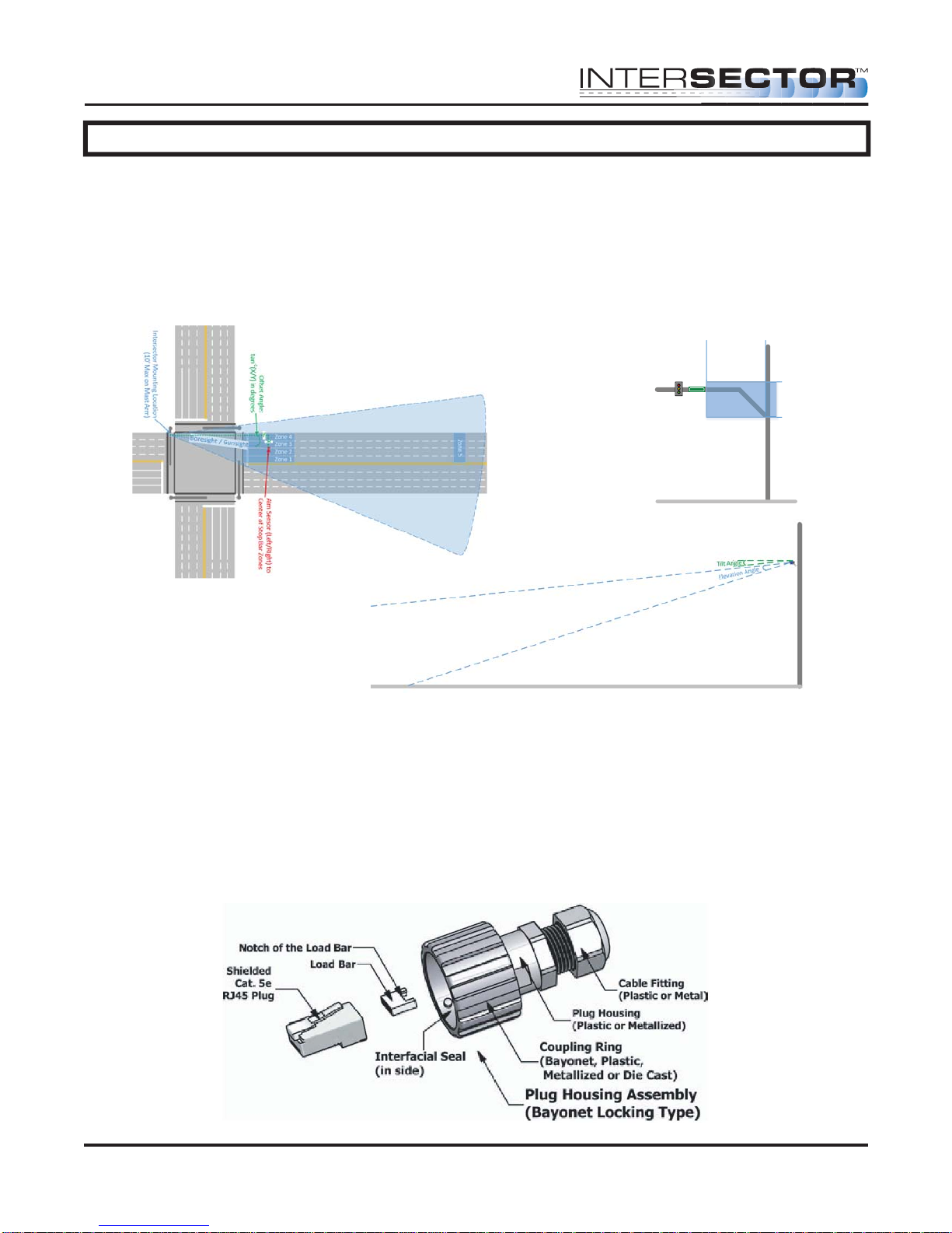
The INTERSECTOR is designed to be mounted at a height of 14 to 20 feet on a corner
signal pole or on a mast arm no further than 10 feet from the signal pole. Maximum
offset angle from traffic direction should be ±15 degrees. Mounting outside this range
may reduce performance. Mount the sensor to the pole using stainless steel banding or
bolts (not included). Make sure the sensor is mounted level.
INTERSECTOR ANGLE SETTINGS:
There are two angle settings for the INTERSECTOR; side to side (azimuth) and up and
down (elevation). The azimuth setting is accomplished visually using the gun sight at
the top of the unit. Aim the gun sight across the center of the stop bar region. Check to
ensure that cars should be tracked approximately 30 feet past the stop bar for a left turn
lane. To set the elevation, use the angle meter which is included in the INTERSECTOR
installation kit. The Installation Table Recommended Settings below provides initial
settings for installation, based on the distance to the stop bar. These settings may need
additional adjustment depending on factors such as the slope of the road. Rotating the
unit downward will decrease total range, but will ensure detection closer to the unit.
INTERSECTOR Microwave Motion and
Presence Sensor Installation Instructions
MS Sedco INTERSECTOR Installation Instructions Page 7 INTERSECTOR-1.9Uv092717
!
INSTALLATION (continued)
Distance ............Max # ................Angle Mounting........................ Height
to Stop Bar Lanes (˚) (ft.)
60-80 feet .................... 2 ...............................-6 degrees .....................................16 feet
80-100 feet .................. 3 ...............................-6 degrees .....................................17 feet
100-120 feet ................ 4 ...............................-4 degrees .....................................18 feet
120-160 feet ................ 4 ...............................-2 degrees .....................................19 feet
Connection of the sensor to the traffic cabinet is accomplished using an Ethernet cable.
The cable is routed through a quick connect assembly that is then connected to the
sensor. The other end of the cable is routed to the traffic cabinet and plugs into the
interface board. The next section will detail the preparation and installation of the
sensor Ethernet cable.
QUICK CONNECT ASSEMBLY INSTRUCTIONS:
The quick connect consists of a shielded Cat. 5e RJ45 Plug, a load bar, and a Plug
Housing Assembly.
INTERSECTOR Microwave Motion and
Presence Sensor Installation Instructions
MS Sedco INTERSECTOR Installation Instructions Page 8 INTERSECTOR-1.9Uv092717
14'
20'
0'
10'
Intersector
Mounng Area
FIGURE 2: Recommended INTERSECTOR™
Mounting Location Depiction
FIGURE 1: INTERSECTOR™ Installation Example
FIGURE 3: INTERSECTOR™ Tilt and
Elevation Angle
INSTALLATION (continued)
It is necessary to prepare the cable and insert it through the housing prior to attaching
the load bar and Ethernet connector (RJ45 plug).
NOTE: Cat.5e direct burial shielded cable is recommended to keep
Electromagnetic Interference, or (EMI), from effecting the ability of the cable to
transmit data. EMI can pass through the cable, corrupting your data and shutting
down communication. The Shielding in the wire helps to prevent this energy from
getting through and causing adverse effects to the TC-CK1-SBE communication
data.
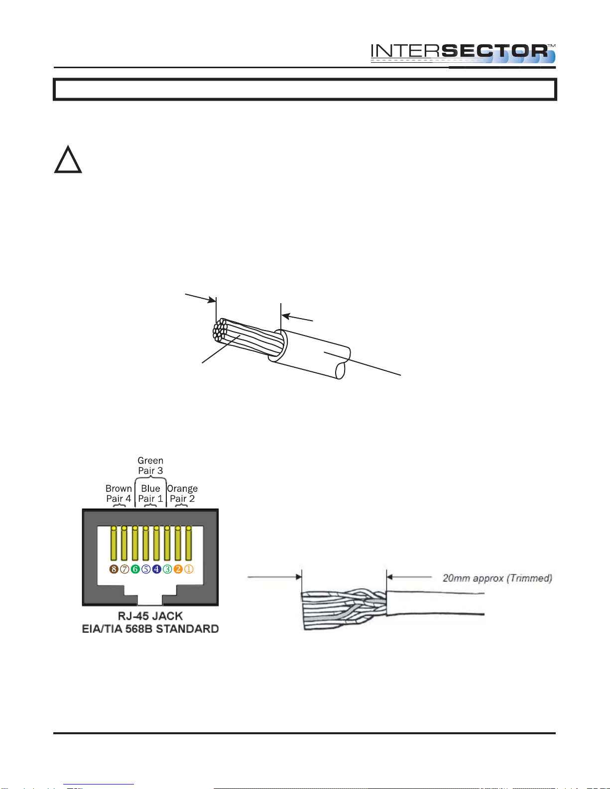
CABLE PREPARATION: Using an 8 conductor, 24 AWG per conductor solid or stranded
cable, the cable jacket should be stripped as shown in Figure 1 and then inserted
through the cable fitting and the plug housing assembly.
Conductors should be untwisted and aligned side by side for a T568B connector. Refer
to Figure 2 to determine the proper alignment of the cable conductors.
The conductor wire ends should be trimmed as shown in Figure 3. Untwist as little of
the cable as possible. Be careful not to remove the insulation of individual conductors!
Figure 2 Figure 3
Figure 1
Strip 25mm length approx.
Jacket
Conductor
INTERSECTOR Microwave Motion and
Presence Sensor Installation Instructions
MS Sedco INTERSECTOR Installation Instructions Page 9 INTERSECTOR-1.9Uv092717
!

Figure 4 Figure 5
INTERSECTOR Microwave Motion and
Presence Sensor Installation Instructions
MS Sedco INTERSECTOR Installation Instructions Page 10 INTERSECTOR-1.9Uv092717
IMPORTANT – No wires should be exposed when the plug is fully in place.
Figure 7
INSTALLATION (continued)
After inserting the wires into the appropriate positions of the load bar, slide the cable to
a point where the cable jacket hits the notch of the load bar. Trim the remaining wire
ends to approximately 5mm length as shown in Figure 4. Retract the cable, leaving
approximately 1mm of wire tips as shown in Figure 5.
Insert the wired load bar into the RJ45 plug all the way until the wire tips are sealed
against the inside wall of the plug housing (Figure 6).
Terminate the cable and the RJ45 plug with a modular plug termination tool similar to
the one shown in Figure 7.
Depress the locking tab of the RJ45 plug and align it with the wide slot of the plug
housing shown in Figure 8 Detail A. Gently pull the cable until the plug is fully seated.
Hold the plug in position and rotate cable fitting until tightened to a torque of 3.4 Nm (30
lb-in) as shown in Figure 8 Detail B.
Figure 6
Table of contents
Other MS Sedco Accessories manuals

MS Sedco
MS Sedco DH97 User manual

MS Sedco
MS Sedco SmartWalk XP User manual

MS Sedco
MS Sedco microStar User manual

MS Sedco
MS Sedco ID20 User manual

MS Sedco
MS Sedco DH94D User manual

MS Sedco
MS Sedco DH400 User manual

MS Sedco
MS Sedco INTERSECTOR SDLC User manual

MS Sedco
MS Sedco DH100-CT User manual

MS Sedco
MS Sedco MicroStar blue User manual


