MS Sedco SmartWalk XP User manual

Page | 1 V102020-01
USER’S GUIDE
SMARTWALK™ XP & XP-S (solar)
Online Manual
DESCRIPTION
The SmartWalk XP & XP-S are the first microwave sensors specifically designed to provide
short range hands-free pedestrian presence detection at the curbside area of a crosswalk or
roadside at a trail crossing. The sensor is intended to be pole-mounted near the crosswalk
and can be used in lieu of the pedestrian crosswalk button.
INCLUDED IN THE BOX SPECIFICATIONS
(1) XP or XP-S Microwave Sensor
(1) Wire Harness –24” Length (with in-line fuse
protection)
(1) 24 Volt, 1A Step-Down Transformer (not incl. in
the XP-S box)
(1) Narrow Antenna (installed)
(1) Installation Instructions
REMOVE THE COVER OF THE SENSOR
Remove (2) ¼” hex head screws at the back cover
and (2) ¼” hex screws at the lower front side.
NOTE: There is NO need to remove any of the
Phillips head screws on the cover.
Lift the cover upward for removal.
All wiring to the sensor and all available
adjustments are made while the cover is off.
PCB IDENTIFICATION
Model
SmartWalk XP & XP-S (solar)
Input Power
XP: 12-24V AC/DC
XP-S: 12 VDC ONLY
Power Consumption
XP: 2W Maximum
XP-S: 1W Maximum
Output Contacts
Form C, Rated at 3 Amps
Relay Contact Ratings
3A:120V AC; 3A:60V DC
Temperature Rating
-22°F to 158°F (-30°C to 70°C)
Weight
4 lbs.
Module Size
7” L x 4” W x 4-1/8” H

Page | 2 V102020-01
PATTERN CHARACTERISTICS
The narrow antenna is factory installed by default. A wide antenna is not used for this product.
The detection pattern shown below is an approximation only. Detection pattern size shown may slightly vary based upon
actual site conditions.
Remember some general rules regarding the behavior of microwave. The zones can be related to the behavior of a
flashlight:
oAs the sensor is pointed straight down, the resulting pattern will be more spherical.
oAs the angle from vertical is increased, the zone will start to extend away and become more elliptical.
oAs the sensor is raised in mounting height, the size of the detection zone also increases.
oIt is not always possible to predict what the exact settings will be for a given application. As such, pick the best
settings based upon these simple facts, then walk test the sensor and adjust for optimal performance as necessary.
SENSORS IN CLOSE PROXIMITY
If an application calls for 2 or more sensors in close proximity to one
another, it is advisable to mix the frequencies to prevent possible
interference from one sensor to another.
If sensors are pointed towards each other or if the detection zones are
extremely close to one another, the frequencies should not be the same.
If in doubt, use different frequencies.
The frequency of each sensor is located on the back exterior vertical face
of the housing and is signified by a letter, typically a B, C, or D located just
above the serial number.
SETTING THE DIPSWITCHES
•Prior to installing the sensor at its mounting location, configure the dipswitches for the
application.
•dipswitches are located at the front end of the circuit board.
•To place a dipswitch in the ON position, move it away from the number of the switch.

Page | 3 V102020-01
SW
DEFAULT
SWITCH DESCRIPTION
SWITCH OFF
SWITCH ON
REMARKS
1
ON
Detection Direction
Uni-Directional
Motion Detection
Bi-Directional Motion
Detection
When Bi-directional detection is
selected, dipswitch 6 is bypassed.
2
OFF
Pedestrian Motion
Sensitivity
Increased Sensitivity
Decreased Sensitivity
3
ON
Pedestrian Presence
Sensitivity
Increased Sensitivity
Decreased Sensitivity
4
OFF
Fail-Safe State
Disabled
Enabled
5
OFF
Pedestrian Presence
Enabled
Disabled
“Detection Verification
Extension”adjustment is
bypassed and set to 0 seconds
when dipswitch 5 is disabled.
6
OFF
Approach / Depart
Approach
Depart
When Approach-Only or Depart-
Only detection is selected, then
dipswitch 1 must be set to
Uni-directional (OFF).
MECHANICAL INSTALLATION
The XP installation is intended for mounting to a utility pole or other rigid structure. The sensor may be directly mounted by
the attaching bracket to a pole, or by banding to the pole.
oNote: Mounting screws and bands are not included in the SmartWalk product box.
Do not connect the input power until the mechanical installation and all wiring is completed.
When installing the XP sensor, the following guidelines must be followed:
o24” maximum offset from edge of crosswalk to pole (dimension X)
oSensor mounting height should be 10’ to 12’ (dimension H)
oThe sensor should be angled out from the vertical plane approximately 15 degrees for optimal performance.

Page | 4 V102020-01
HELPFUL HINTS FOR MOUNTING & LOCATION
Try to keep the mounting height at approx. 10’ to 12’. Higher mounting heights will increase the size of the detection zone
and will make it difficult to prevent unwanted vehicle detection as the targeted zone may extend into the roadway. Fine
tuning can be obtained by adjusting the “range” setting.
Ideally, the distance from the pole to the edge of the crosswalk should be about 2’. This is to accommodate an optimal 15-
degree angle on the sensor when it is mounted at 10’ to 12’. As the sensor is mounted higher, the sensor angle may need to
be adjusted to detect within the targeted detection zone. At higher mounting heights, the sensor may be more prone to
unwanted vehicle detection as part of the zone may be in the roadway –depends on pole location relative to the crosswalk.
If an inclinometer is unavailable to determine mounting angle, simply measure the distance from the mounting surface for
the sensor bracket (such as a pole) to the bottom corner of the sensor. When the sensor is at approx. 15 degrees, this
dimension will be approx. 7”. Remember, if the pole is further from the crosswalk, this angle may need to be slightly
increased.
LED INDICATIONS
LED’s are located on the PCB and are viewable with top cover removed.
LED 1 STATUS
PERFORMANCE
Solid Green
Sensor is on and is in a state of non-detection.
Flashing Red
There is movement within the detection zone but not enough to trigger the sensors output.
Solid Red
Detection has occurred and the output is active.
LED 2 STATUS
Solid Orange
Sensor is detecting movement within the detection zone.
WIRING
The electrical connection terminal is at the back end of the sensor. The 24” harness is pre-wired at the factory as follows:

Page | 5 V102020-01
POWER-ON & SETUP
Confirm all electrical connections have been completed and the sensor is in its proper mounting location.
Apply low voltage power to the sensor. Do not ground the secondary side of the transformer.
Observe the LED indication at the top of the sensor –the following
should occur:
oThe sensor shall blink green 3 times once power has been
applied
oThe sensor LED changes to a solid green indicating sensor is
ready for setup and alignment.
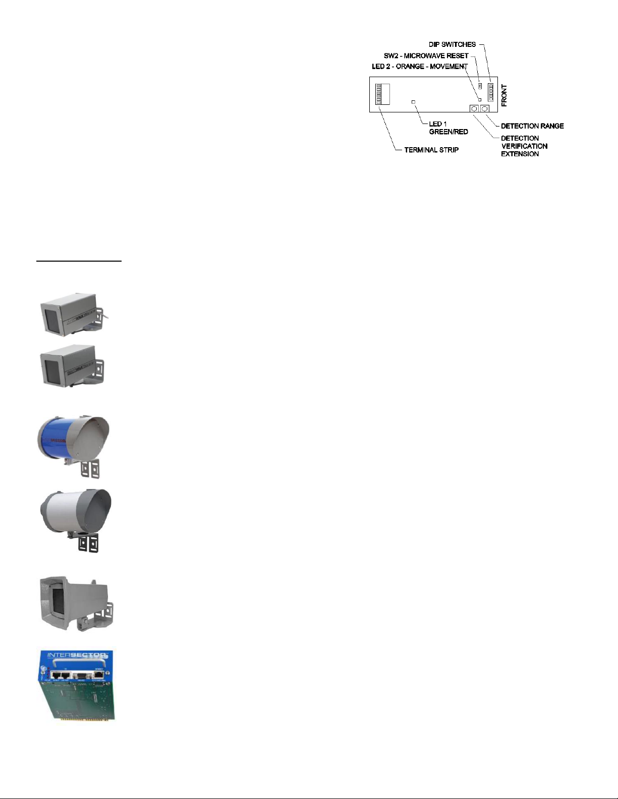
To simplify the initial walk-test of the detection zone, check to
ensure the potentiometer for the “Detection Verification Extension”
is set at its minimum value –all the way counter-clockwise.
To determine the detection zone, walk in and out of the targeted detection zone and note the trigger points of the area so
it can be mapped out on the sidewalk.
oNote: The sensor will detect human movement in a direction defined by the value of dipswitch #1.
oIf the sensor is set to uni-directional mode, it will only detect movements of a frontal approach to the sensor.
If the sensor is set to bi-directional, it will detect movements toward the
sensor from any direction.
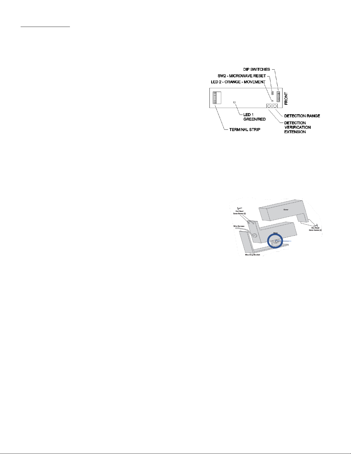
If the position of the targeted detection zone is incorrect for the application,
re-aim the sensor for better alignment to the intended area of detection. This
can be done by loosening the hinge bolt of the sensor to adjust angle, or by
loosening the bracket attachment screws to for lateral adjustment. Make the
proper adjustments and then re-tighten the hardware.
HELPFUL HINTS:
oRemember to walk-test the entire targeted detection zone , mapping out the zone to ensure it is providing
adequate detection coverage.
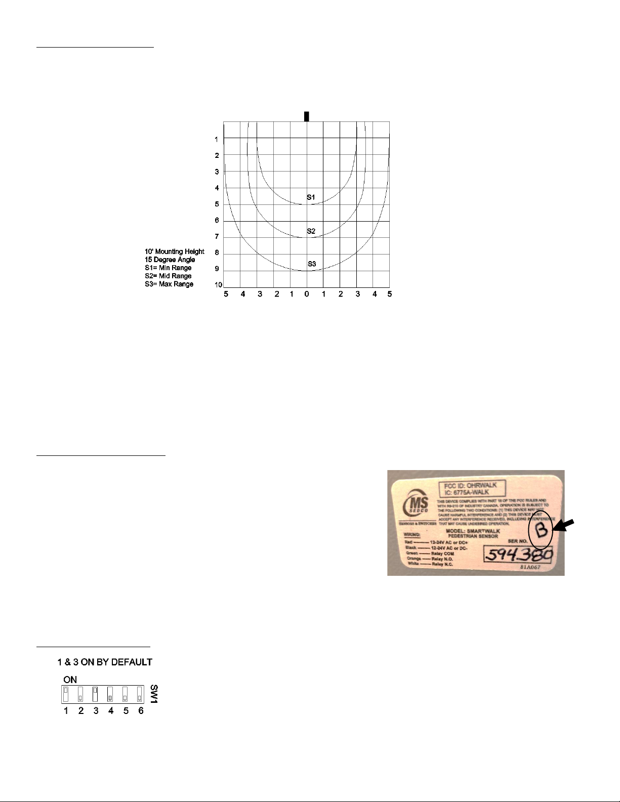
oThe “Range” adjustment potentiometer can be used to effectively enlarge or reduce the detection zone. By
default, the range is at its maximum setting.
oHigher mounting heights equate to larger detection zones. As such, if the sensor must be mounted higher than 10’
due to obstructions on the pole, such as signage, it will require more care in the setup to try and eliminate un-
wanted detections from peripheral movements on the sidewalk or even cars passing through the intersection near
the curb. If the sensor is unable to perform sufficiently at the higher height, a lower mounting position may be
necessary.
oWhen the sensor is configured for uni-directional detection, it will require more of a frontal approach to the sensor
to achieve detection in the targeted detection zone. As one progressively moves off center from a frontal approach
to a side or rear approach, the sensor will eventually no longer detect you. If detection from any direction is
desired, set dipswitch #1 to bi-directional detection.
Hinge Bolt

Page | 6 V102020-01
Walk in and out of the targeted detection zone to ensure the sensor
is detecting from all targeted degrees of approach. If sensitivity is
incorrect, alter the setting of the “range adjustment” potentiometer
located on the sensor. Clockwise rotation will increase sensitivity
which in turn increases zone size.
As a last adjustment, note the “Detection Verification Extension”.
This function is used to provide a delay between the point of
detection and the point of sending an output to the controller. The
most common reason to add a delay is to help avoid unwanted detections that occur from people that may be passing by
the outer fringe of the targeted detection zone or by the occasional stray detection caused by a nearby movement of a
vehicle, for example. Keep in mind, as the timer is increased, so too then is the time it takes to detect an intended approach
to the sensor. For a typical crosswalk environment , the timer is usually never more than 1-2 seconds. Adjust per your
specific application.
RELATED PRODUCTS
The SmartWalk XM is designed to monitor the curbside lane of a crosswalk for pedestrian occupancy and
provide an extension of the pedestrian clearance timer.
The SmartWalk TX microwave sensor is specifically designed to monitor trails for users approaching a road
crossing from up to 60 feet away.
Intersector™- (PN: TC-CK1-SBE) microwave based vehicle motion and presence detector
VMS Intersector™ - (PN: TC-CK1-VMS) microwave based vehicle motion detector
TC26-B - microwave based vehicle motion detector
Intersector™- TCIB Interface Boards

Page | 7 V102020-01
RMA PROCEDURE
Upon confirmation of a failed product, an RMA form must be filled out online prior to returning the product
to MS Sedco.
Go To: https://mssedco.com/return-repair-policy-form/
Or scan the QR code with your smartphone to go directly to the online form.
TERMS OF WARRANTY
MS SEDCO, Inc. guarantees this product to be free from manufacturing defects for three years from the date of
shipment from our factory. If, during this period, the product fails to operate and has not been tampered with or
abused, the unit can be returned prepaid to the factory and be repaired free of charge. After three years, the unit will be
repaired for a nominal service charge. No repairs will be made if the product is older than 8 years from date of invoice.
The terms of warranty apply to the original buyer of the product and are not transferrable. Limited warranty is in lieu of
all other warranties, expressed or implied, including any implied warrantability of merchantability. No representative or
person is authorized to assume for MS SEDCO any other liability in connection with the sale of our products. All
warranties are limited to the duration of this written limited warranty. In no event shall MS SEDCO be liable for any
special, incidental, consequential or other damage arising from any unclaimed breach of warranty as to its products or
services. Terms of warranty are subject to change without notice.
COMPANY CONTACT
MS SEDCO
7898 Zionsville Rd.
Indianapolis, IN 46268
Phone: 317-842-2545
www.mssedco.com
This manual suits for next models
1
Table of contents
Other MS Sedco Accessories manuals

MS Sedco
MS Sedco INTERSECTOR SDLC User manual

MS Sedco
MS Sedco DH100-CT User manual

MS Sedco
MS Sedco ID20 User manual

MS Sedco
MS Sedco DH400 User manual

MS Sedco
MS Sedco INTERSECTOR User manual

MS Sedco
MS Sedco microStar User manual

MS Sedco
MS Sedco DH94D User manual

MS Sedco
MS Sedco DH97 User manual

MS Sedco
MS Sedco MicroStar blue User manual