MS Sedco DH97 User manual

Sensor's
Cable
Connection
Cable
Red & Black = Power [Nonpole]
Yellow = Normally Open [NO]
Green = Normally Closed [NC]
White = Common
DH97
4-Row Active Infrared Presence Detector for Automatic Door Control INSTALLATION INSTRUCTIONS
8701 Castle Park Drive Indianapolis, Indiana 46256
Telephone: (800) 842-2545/(317) 842-2545 www.mssedco.com custsvc@mssedco.com
Page 1
(82A042) DH97v0504
Section 1
General Description
The DH97 is a 4-row microprocessor controlled active
infrared presence detector for all types of automatic
doors.
• Wide and narrow pattern width of the
sensor is adjustable by twin revolving lens
units.
• Pattern depth and width are
adjustable using mounting height,
dip switches, pattern width and
pattern angle adjustments.
• Frequency is selectable in four channels
• Self-Diagnostic means the sensor continuously
monitors itself.
• Snow Mode Switch ensures against false operation
caused by snow, insects, etc.
• Microprocessor provides programmable Presence
Timer (2, 15, 60 or 180 seconds).
Section 2
Parts Identification
Section 3
Mounting Information
1. Do not mount higher than 10 ft. (3m).
2. Do not leave any objects which may move in the
detection pattern.
3. Do not mount where rain or snow will fall directly on
unit.
4. Do not mount in a place where reflection of sunlight
will shine on unit.
5. Do not mount in a humid or steamy environment.
6. Do not mount five devices in proximity to each other.
When using from 2 to 4 devices in proximity, use
alternate frequency settings as shown below.
(Maximum 4 sensors)
Section 4
Mounting and Wiring
1. Using the mounting template provided, drill mounting
and wire holes.
2. Remove cover using a screwdriver.
3. Fasten unit with mounting screws provided.
4. Connect wiring. Push amp connectors tightly
together.
M
ountin
g
Template
Mounting
Screws
Connection Cable
5 ft. (1.5m)
Instructions
A
ccesso
r
ies
Use Alternate Frequency.
12 3
4 5 6
H/MH/ML/L
DIP Switches Sensitivity
tte
r
n
Wi
dt
h
Connector
Mounting Holes
Cover
10Ft.

SIDE VIEW/DETECTION PATTERN
Max Area Min Area
Maximum Angle
( 10 º )
Minimum Angle
( 0º )
0
1.6'
0.5m
3.3'
1.0m
4.9'
1.5m
6.6'
2.0m
8.2'
2.5m
9.9'
3.0m
3.5m 3.0m 2.5m 2.0m 1.5m 1.0m 0.5m 0
11.5' 9.8' 8.2' 6.6' 4.9' 3.3' 1.6' 0'
2.5m 2.0m 1.5m 1.0m 0.5m 0m
8.2' 6.6' 4.9' 3.3' 1.6' 0'
10°
1R2R3R4R
Presence
3R
4R
Presence
2R 1R
Mounting and Wiring (continued)
5. Set desired sensor parameters as noted in Sections
5 & 7.
6. Place cover on sensor and clean the sensor.
NOTE: For maximum pattern depth and width,
mount the DH97 at 10 feet and use the
maximum pattern angle (10º).
NOTE: The DH97 can be mounted using the
optional DH97-BDB or DH97-MP mounting
brackets when more flexible mounting is
required (See Page 5).
Section 5
Dip Switch Settings
1&2 Presence Timer: Timer is adjustable using
switches 1 and 2. 1 to 4 Rows will detect a
stationary object for the time period set by the
Presence Timer. The timer will reset and begin if
any movement is detected.
3&4 Pattern Depth (Rows): To adjust the pattern
depth, set switches 3 & 4 as shown.
5&6 Frequency: When more than two sensors are
used in close proximity to each other, to prevent
interference use alternate frequency settings.
(H + MH + ML + L = Maximum 4 sensors).
7 Monitor Mode: A Snow Mode is available. Snow
Mode should only be used in environments with
heavy snowfall or other extreme conditions.
8 Self-Monitoring: "ON"=When power is first
supplied to the DH97, the sensor automatically
performs a Self Diagnosis (See Section 9).
Section 6
Power
BEFORE APPLYING POWER, READ AND FOLLOW THESE
INSTRUCTIONS:
When power is applied, the sensor will read and store the
environmental optical parameters. This is necessary for
Presence Detection to work properly.
1. CLEAR THE AREA OF ANY UNNECESSARY OBJECTS.
2. Apply POWER.
3. Vacate the Detection Pattern immediately. While the
sensor sees ANY moving objects in its DETECTION
PATTERN, it will not proceed to the following step.
4. DO NOT enter DETECTION PATTERN for 10 seconds
(Presence Detection Setting).
5. TEST the presence feature, especially near the door.
When carrying out the following work, TURN OFF THE
POWER:
1. When the floor conditions change.
2. Adjusting pattern or sensitivity.
Section 7
Adjusting Detection Pattern
Adjust the detection pattern according to the following
diagrams:
1. Pattern Angle Adjustment.
• The body of the sensor can be rotated from 0º to
10º (5 steps).
8701 Castle Park Drive Indianapolis, Indiana 46256
Telephone: (800) 842-2545/(317) 842-2545 www.mssedco.com custsvc@mssedco.com
Page 2
(82A042) DH97v0504
5. DIP Switch Settings
7. Adjusting Detection Pattern
>
>
!
!
DH97
4-Row Active Infrared Presence Detector for Automatic Door Control INSTALLATION INSTRUCTIONS
60 Sec
15 Sec
2 Sec
180 Sec
12
L
MH
H
56
ML
1 R
2 R
3 R
4 R
34
Snow
ON
DEFAULT
SETTINGS 12345678
OFF
ON
8
Normal
7
Presence
Timer
Pattern Depth
(Rows) Frequency Self
Monitoring
Monitor
mode
1
R
2
R
3
R
4
R

Sensitivity
2. Pattern Width Adjustment.
Pattern Adjustments for single and/or double doors by
Side Lever.
Detection pattern will vary according to
objects, material, color and speed.
Section 8
Verification of Operation
1. After mounting, setting parameters and applying
power, walk test unit to verify detection pattern.
2. If the door does not operate properly, recheck the dip
switch settings and pattern adjustments.
3. After rechecking, if there is still a problem, adjust the
sensitivity.
• Adjust high (clockwise) to increase sensitivity.
• Adjust low (counter-clockwise) to decrease
sensitivity.
APPLY ONLY SMALL TORQUE
Section 9
Self Monitoring
Infrared beams are received on the receiver side of the
DH97, then the following occurs. For 12 seconds, the
relay starts chattering ON/OFF (4 times in 12 seconds).
Then the relay remains in the ON condition for 60
seconds. The cycle then repeats itself. At the same time,
the Indicator LED will switch continuously between RED
and GREEN. The door will remain in an Open position
throughout.
*****EXTREMELY IMPORTANT*****
After final set-up, test unit(s) completely to ensure that
proper coverage has been achieved (width, depth and
location of the pattern must be tested).
After the installation and operational check of the
system:
1. Place the proper labels on the door per ANSI/BHMA
A156.10 & BS 7036.
2. Instruct the owner of the door system operation and
how to test it. This should be checked on a daily
basis.
3. Instruct the owner on what to do if the door or any of
its components become damaged.
4. Strongly recommend to the owner that the complete
entry be inspected twice a year as part of the service
agreement.
Section 10
Troubleshooting
PROBLEM 1: Door does not open
CAUSE 1: Sensor Connector
SOLUTION 1: Tighten connector or reconnect
CAUSE 2: Power Supply
SOLUTION 2: Check that the power supply is properly
connected and 12V to 24V AC or DC
PROBLEM 2: Door operates intermittently
CAUSE 1: Sensor is very dusty or covered in water
drops, etc.
SOLUTION 1: Clean the sensor (do not use thinner or
alcohol to clean sensor)
CAUSE 2: Sensitivity too low
SOLUTION 2: Turn up sensitivity
CAUSE 3: Detection pattern in the wrong position
SOLUTION 3: Alter the detection pattern by changing
sensor angle, dip switch settings and/or
pattern width adjustments
8701 Castle Park Drive Indianapolis, Indiana 46256
Telephone: (800) 842-2545/(317) 842-2545 www.mssedco.com custsvc@mssedco.com
Page 3
(82A042) DH97v0504
!
!
4-Row Active Infrared Presence Detector for Automatic Door Control INSTALLATION INSTRUCTIONS
DH97
FRONTAL VIEW/DETECTION PATTERN
Side lever Adjustment
L
15432
R
1
54 32
L
4
R
4
L
1
R
1
Do not use Position 5
WIDE NARROW
0
1.6'
0.5m
3.3'
1.0m
4.9'
1.5m
6.6'
2.0m
8.2'
2.5m
9.9'
3.0m
2.5 2.0 1.5 1.0 0.5 0.5 1.0 1.5 2.0 2. 5
8.2' 6.6' 4.9' 3.3' 1.6' 1.6' 3.3' 4.9' 6.6' 8.2'
2.5 2.0 1.5 1.0 0.5 0.5 1.0 1.5 2.0 2. 5
8.2' 6.6' 4.9' 3.3' 1.6' 1.6' 3.3' 4.9' 6.6' 8.2'
11.25
11.25
°
°
Relay Output Timing Chart
12 sec
1 cycle
12 sec
60 sec
ON
OFF
(When no reflection)

PROBLEM 3: Door operates by itself
CAUSE 1: Sensitivity too high
SOLUTION 1: Turn down sensitivity
CAUSE 2: Another sensor is too close by
SOLUTION 2: Change the frequency to each sensor
CAUSE 3: Sensor detects the door movement
SOLUTION 3: If the indicator LED is an Orange color,
adjust the pattern depth angle away
from the door
CAUSE 4: There is a cloth mat in the detection
pattern
SOLUTION 4: Turn the sensor power off and then on
again, and allow it 10 seconds to
reprogram
CAUSE 5: Detection pattern too far in front of the
door, detecting people passing by
SOLUTION 5: Adjust the detection pattern - move it
closer to the door
CAUSE 6: The condition of the monitored area is
varying (i.e., dusty, dirty, snow)
SOLUTION 6: The condition of the detection zone can
change due to heavy dust or dirty, heavy
snow or footprints being left in fresh
snow. This will cause the door to open
sometimes. Set the Presence Timer to a
short time. (See Section 5)
Section 11
Technical Data
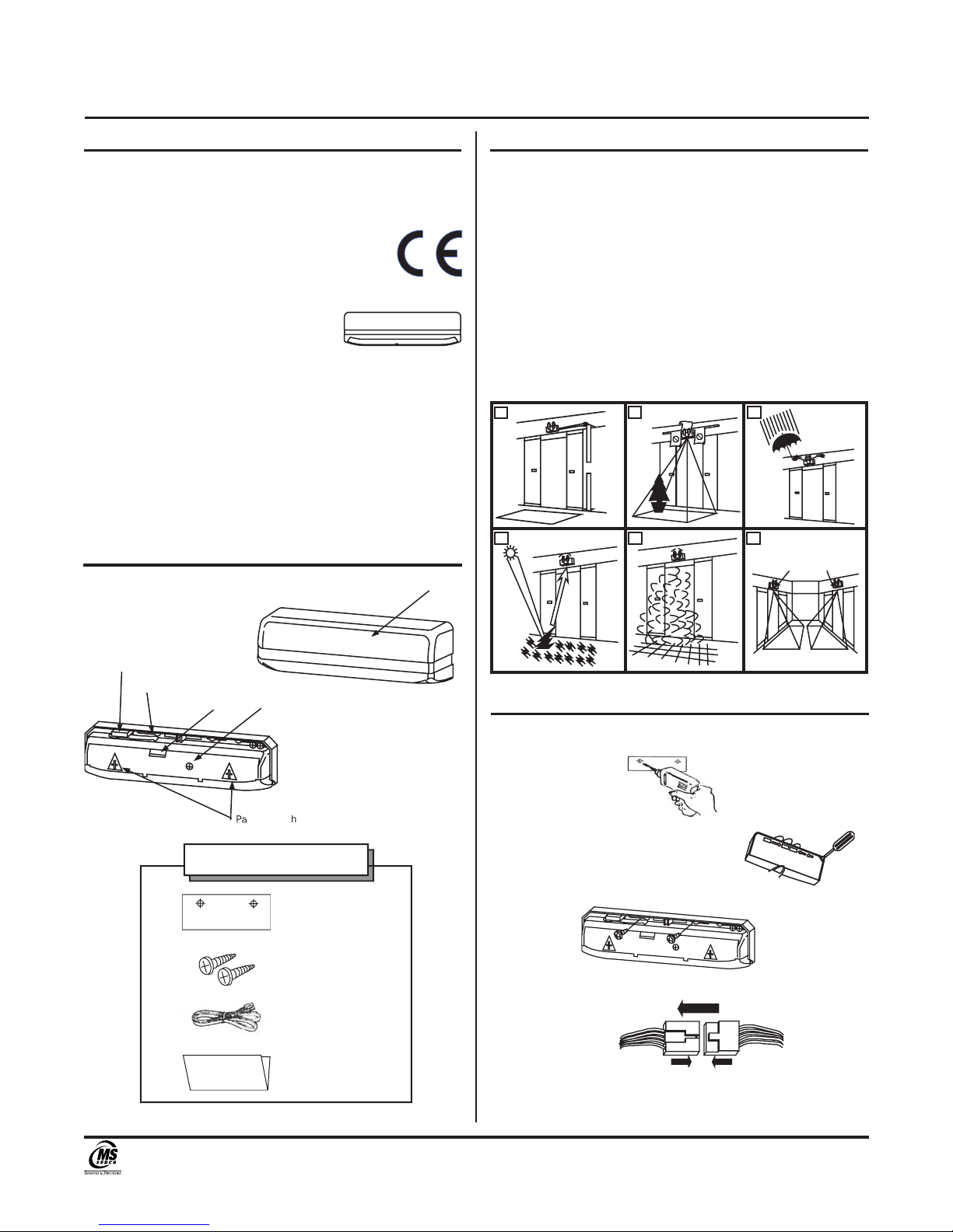
Model................................ DH97 Presence Detector
Detection Method.............Active Infrared Detection
Max. Installed Height....... 10 ft. (3m)
Pattern Adjustments........ Pattern Width (wide or narrow-
side lever 1 to 4 position)
Pattern Depth (1 to 4 rows)
Angle Adjustment 0º to 10º in 5
steps
Detection Beams..............8 Beams * 4 Rows = 32 Beams
Presence Detection..........1 to 4 Rows by Presence Timer
Power Supply.................... 12 to 24 V AC or DC ± 10%
Power Consumption......... AC24V-3VA, AC12V-3VA
DC24V-75mA, DC12V-150mA
Output Contact................. Form C Relay: DC50V 0.1A
(Resistor Load)
Yellow Wire = Normally Open
Green Wire = Normally Closed
White Wire = Common
Output Holding Time........ Approx. 0.5 seconds
Presence Timer.................Limits of 2, 15, 60 and 180
seconds (Row 1 to 4)
LED Indication.................. RED = Detecting
GREEN = Standby
ORANGE = Hunting Door
Protection..........................IP54 (IEC60529)
Temperature Range......... -4°F to 140°F
(-20°C to 60°C)
Weight............................... 0.77 lbs. (0.35kg)
Color.................................. Black
Accessories.......................Cable: 5 ft. (1.5m)
Mounting Template
Installation Instructions
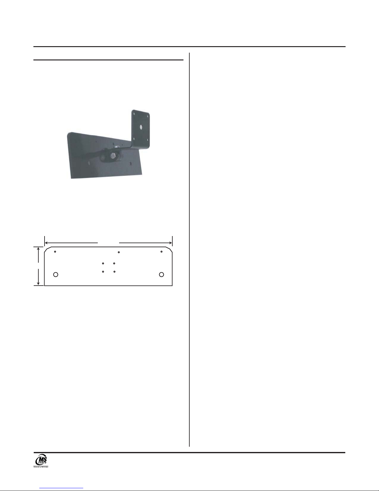
Section 12
E
x
t
ernal D
i
mens
i
on
s
Section 13
Warranty
MS SEDCO guarantees this product to be free from manufacturing
defects for 3 years from date of installation. Unless MS SEDCO is
notified of the date of installation, the warranty will be in effect for
3 years from the date of shipment from our factory. If, during the
first 3 years, our motion detector or support device fails to operate
and has not been tampered with our abused, the unit can be
returned prepaid to factory and it will be repaired free of charge.
After 3 years, the unit will be repaired for a nominal service
charge. This limited warranty is in lieu of all other warranties
expressed or implied, including any implied warranty of
merchantability, and no representative or person is authorized
to assume for MS SEDCO any other liability in connection with
the sale of our products. All warranties are limited to the
duration of this written warranty. In no event shall MS SEDCO
be liable for any special, incidental, consequential or other
damages arising from any claimed breach of warranty as to its
products or services.
8701 Castle Park Drive Indianapolis, Indiana 46256
Telephone: (800) 842-2545/(317) 842-2545 www.mssedco.com custsvc@mssedco.com
Page 4
(82A042) DH97v0504
4-Row Active Infrared Presence Detector for Automatic Door Control INSTALLATION INSTRUCTIONS
DH97

Section 14
DH97-BDB Backplate/Bracket and DH97-MP
Mounting Plate
The DH97-BDB is an optional bracket for the DH97
sensor. It allows universal aim adjustment and adapts
the DH97 for unique mounting requirements.
DH97-BDB
The DH97-MP is an optional mounting plate that adapts
the DH97 sensor for mounting to a 1 3/4" door header. It
can also be field prepped for a variety of unique mounting
applications.
DH97-MP
(drawing not to scale)
8701 Castle Park Drive Indianapolis, Indiana 46256
Telephone: (800) 842-2545/(317) 842-2545 www.mssedco.com custsvc@mssedco.com
Page 5
(82A042) DH97v0504
4-Row Active Infrared Presence Detector for Automatic Door Control INSTALLATION INSTRUCTIONS
DH97
10 1/4"
3"
Table of contents
Other MS Sedco Accessories manuals

MS Sedco
MS Sedco DH100-CT User manual

MS Sedco
MS Sedco microStar User manual

MS Sedco
MS Sedco INTERSECTOR User manual

MS Sedco
MS Sedco DH94D User manual

MS Sedco
MS Sedco ID20 User manual

MS Sedco
MS Sedco INTERSECTOR SDLC User manual

MS Sedco
MS Sedco SmartWalk XP User manual

MS Sedco
MS Sedco MicroStar blue User manual

MS Sedco
MS Sedco DH400 User manual
Popular Accessories manuals by other brands

Philips
Philips SCF616/10 Product highlights

D+H
D+H REM 801-RC Original instructions

GE
GE JASCO 32563 quick start guide

Pepperl+Fuchs
Pepperl+Fuchs 3RG7256-3NQ00-PF Mounting and operating instructions

HB Products
HB Products HBDF MK2 instruction manual

CommScope
CommScope AMP NETCONNECT 553947 Series instruction sheet