MS Sedco DH400 User manual

DH400
High Mount Active Infrared Presence Detector for Automatic Door Control INSTALLATION INSTRUCTIONS
Page 1
DH400v1214
Section 1
General Description
The DH400 is a high mount microprocessor controlled
active infrared presence detector for all types of
automatic doors.
•Wide and narrow pattern width of the sensor
is adjustable.
•Pattern depth and width are
adjustable using mounting height,
dip switches, pattern width and
pattern angle adjustments.
•Frequency is selectable in four channels
•Self-Diagnostic means the sensor continuously
monitors itself.
•Snow Mode Switch ensures against false operation
caused by snow, insects, etc.
•Microprocessor provides programmable Presence
Timer (2 sec., 30 sec., 60 sec., or infinity).
Section 2
Parts Identification
Section 3
Mounting Information
1. Do not mount higher than 13.1 ft. (4m).
2. Mount within 1.97” from the bottom of the
door engine cover.
3. Do not leave any objects which may move in the
detection pattern.
4. Do not mount in a humid or steamy environment.
5. Do not mount where rain or snow will fall directly on
unit.
6. Do not mount where snow or water will accumulate
on floor if possible.
7. Do not mount in a place where reflection of sunlight
will shine on unit.
8. Use different frequency settings for sensor in close
proximity.
To maximize the effectiveness of doorway detection,
install the DH400 outside and inside as shown below.
Mounting
Template
Mounting
Screws
Connection Cable
8.2 ft. (2.5m)
Instructions
Installation
Accessories
Use Alternate Frequency.
12 3
4 5 6
7 8
A B
Dip Switch
Cover
13.1Ft.
NOTE: Set up for this sensor should be
performed by an AAADM-certified installer.
8701 Castle Park Drive Indianapolis, Indiana 46256
Telephone: (317) 842-2545 www.mssedco.com custsvc@mssedco.com
Connector
Potentiometer
(Sensitivity Volume)
Indicator LED
Depth Adjustment Screw
Mounting Screw
(2pcs.)
Detection Window
Width Adjustment Knob
A B
Side View Plan View
Moving Door Leaf Moving Door Leaf
A
B

Section 4
Mounting and Wiring
1. Using the mounting template provided, drill mounting
and wire holes.
2. Remove cover of unit.
3. Fasten unit with mounting screws provided.
4. Connect wiring. Push amp connectors tightly
together.
5. House connectors in
the recepticle.
6. Replace cover.
Section 5
Dip Switch Settings
Dip Switch X
& Presence Timer: The sensor will detect a
stationary object for the time period set by the
Presence Timer. The timer will reset and begin if
any movement is detected.
& Frequency: When more than two sensors are
used in close proximity to each other, to prevent
interference use alternate frequency settings.
& Pattern Depth (Rows): To adjust the pattern
depth, set switches 3 & 4 as shown.
& Monitor Mode: A Snow Mode is available. Snow
Mode should only be used in environments with
heavy snowfall or other extreme conditions.
Dip Switch Y
& Pattern Width (Left Side): The left side detection
area for approaching direction can be fixed by
setting to 6, 4 or 2 rows.
6 Rows 4 Rows 2 Rows
& Pattern Width (Right Side): The right side
detection area for approaching direction can be
fixed by setting to 6, 4, or 2 rows.
6 Rows 4 Rows 2 Rows
& Installation Height: Set to installation height
required.
NOTE: Set the sensitivity after setting the
mounting height. Refer to Section 8: Verification
of Operation regarding the standard of sensitivity
corresponding to mounting height.
Page 2
DH400v1214
DH400
High Mount Active Infrared Presence Detector for Automatic Door Control INSTALLATION INSTRUCTIONS
8701 Castle Park Drive Indianapolis, Indiana 46256
Telephone: (317) 842-2545 www.mssedco.com custsvc@mssedco.com
60 Sec
*30 Sec
2 Sec
∞Sec
ON
Dip Switches are
depicted in the
Default position.
* = Default 1 2 3 4 5 6 7 8
Presence
Timer
D
B
*A
C
Frequency
*Normal
Snow 1
Snow 2
Snow 3
Monitor
Mode
2R
3R
4R
*5R
Pattern Depth
(Rows)
2
R
3
R
4
R
5
R
*
*R6
R4
R2
R2
ON
Dip Switches are
depicted in the
Default position.
* = Default 1 2 3 4 5 6 7 8
*Off
On
*Off
On
Direction
Detection
Doorway
Learn
*6.6’ - 8.2’
8.2’ - 9.8’
9.8’ - 11.5’
11.5’ - 13.1’
Installation
Height
Pattern Width
(Left)
*R6
R4
R2
R2
Pattern Width
(Right)
Sensor's
Cable
Connection
Cable
Red & Black = Power
Yellow = Normally Open [NO]
Green = Normally Closed [NC]
White = Common

Direction Detection: When set to ON, pedestrians
moving away from the sensor will NOT be detected.
NOTE: For pedestrian safety purposes when
“Doorway Learn” is set to ON, the 1st and 2nd row
of detection will detect pedestrians regardless of
direction of movement.
Doorway Learn: Allows the 1st row of detection to
be focused inside the door close area without
detecting the door movement.
NOTE: When “Doorway Learn” is turned ON, the
sensitivity level of the 1st row of detection is at
maximum only when the outer rows of detection
are activated.
Section 6
Power & “Doorway Learn” Setting
BEFORE APPLYING POWER, READ AND FOLLOW THESE
INSTRUCTIONS:
When power is applied, the sensor will read and store the
environmental optical parameters. This is necessary for
Presence Detection to work properly.
1. CLEAR THE AREA OF ANY UNNECESSARY OBJECTS.
2. Apply POWER.
3. Vacate the Detection Pattern immediately. While the
sensor sees ANY moving objects in its DETECTION
PATTERN, it will not proceed to the following step.
4. DO NOT enter DETECTION PATTERN for 10 seconds
(Presence Detection Setting).
5. TEST the presence feature, especially near the door.
When carrying out the following work, TURN OFF THE
POWER:
1. When the floor conditions change.
2. Adjusting pattern or sensitivity.
“DOORWAY LEARN” is OFF
(Ref. Sec. 5-Dip Switch Settings)
•Upon power ON, the solid Green LED turns on
indicating that the sensor is in standby mode and
ready to detect.
“Doorway Learn” is OFF (Cont.)
Presence Detection: It takes 10 seconds after the sensor
powers up for presence detection to be initiated on all
rows of detection. If someone enters the detection area
before 10 seconds has elapsed, the sensor will continue
to initialize until after 5 seconds with no motion being
detected.
“DOORWAY LEARN” is ON
(Ref. Sec. 5-Dip Switch Settings)
•Upon power ON, the Red LED indicates a door open
relay output to begin the “Doorway Learn” process.
•Green LED blinks for 37 seconds while the “Doorway
Learn” process is carried out. Door opens/closes.
Page 3
DH400v1214
High Mount Active Infrared Presence Detector for Automatic Door Control INSTALLATION INSTRUCTIONS
DH400
8701 Castle Park Drive Indianapolis, Indiana 46256
Telephone: (317) 842-2545 www.mssedco.com custsvc@mssedco.com
Green solid LED
Red solid LED
Green blinking LED
Green blinking LED

•After the “Doorway Learn” process is completed,
sensor is in standby mode.
Presence Detection: During the “Doorway Learn”
process, the outer 4 rows of detection on the DH400
sensor switch from motion detection to presence
detection 10 seconds after power ON. The inner
“Doorway Learn” row of detection will switch from motion
to presence detection after the “Doorway Learn” process
is complete.
“Doorway Learn” Failure & Recovery: If a person enters
the detection area during the “Doorway Learn” process, it
may not be successfully completed. In this case, the
sensor will carry out the “Doorway Learn” process on
door activation caused by a person in order to build an
accurate image of the door open and door close position.
NOTE: When “Doorway Learn” is turned ON, the
sensitivity level of the inner row of detection is at
maximum ONLY when the outer rows of detection are
activated.
CAUTION: If you change dip switch setting or
sensitivity volume, the sensor will be reest.
During resetting, indiator LED is blinking with
orange color. Keep away from detection area.
After resetting, the sensor becomes the same
state as it is turned Power-on.
In case the product is used as a supplementary
sensor: Set the detection area of the 1st row
away from the door.
Section 7
Adjusting Detection Pattern
Adjust the detection pattern according to the following
diagrams:
1. Pattern Angle Adjustment.
SIDE VIEW
FRONT VIEW
Page 4
DH400v1214
High Mount Active Infrared Presence Detector for Automatic Door Control INSTALLATION INSTRUCTIONS
DH400
8701 Castle Park Drive Indianapolis, Indiana 46256
Telephone: (317) 842-2545 www.mssedco.com custsvc@mssedco.com
Green solid LED
!
17.0’ (5.18m)
3.61’ (1.1m)

Relay Output Timing Chart
12 sec
1 cycle
12 sec
60 sec
MAKE
BREAK
(When no reflection)
2. Pattern Width Adjustment.
Pattern Adjustments for single and/or double doors.
See Section 5: Dip Switch Settings for details on dip
switch settings adjustments for Detection Depth and
Width.
Further depth adjustments can be made using the Depth
Adjustment Screw. Rotate clockwise to obtain outermost
setting of 15°. Rotate counter-clockwise to adjust
minimum/innermost setting to 0°.
Section 8
Verification of Operation
1. After mounting, setting parameters and applying
power, walk test unit to verify detection pattern.
2. If the door does not operate properly, recheck the dip
switch settings and pattern adjustments.
3. After rechecking, if there is still a problem, adjust the
sensitivity.
•Adjust high (clockwise) to increase sensitivity.
•Adjust low (counter-clockwise) to decrease
sensitivity.
APPLY ONLY SMALL TORQUE
Standard of sensitivity volume setting depending on
Mounting Height:
Height Setting Setting Standard
6.6’ (2.0m) - 8.2’ (2.5m) 4
8.2’ (2.5m) - 9.8’ (3.0m) 5
9.8’ (3.0m) - 11.5’ (3.5m) *6
11.5’ (3.5m) - 13.1’ (4.0m) 7
Section 9
Self Monitoring
When the sensor has an internal sensor error, the door
will remain open and the Green/Red LED blinks
alternately.
Page 5
DH400v1214
High Mount Active Infrared Presence Detector for Automatic Door Control INSTALLATION INSTRUCTIONS
DH400
8701 Castle Park Drive Indianapolis, Indiana 46256
Telephone: (317) 842-2545 www.mssedco.com custsvc@mssedco.com

Self Monitoring (cont.)
*****EXTREMELY IMPORTANT*****
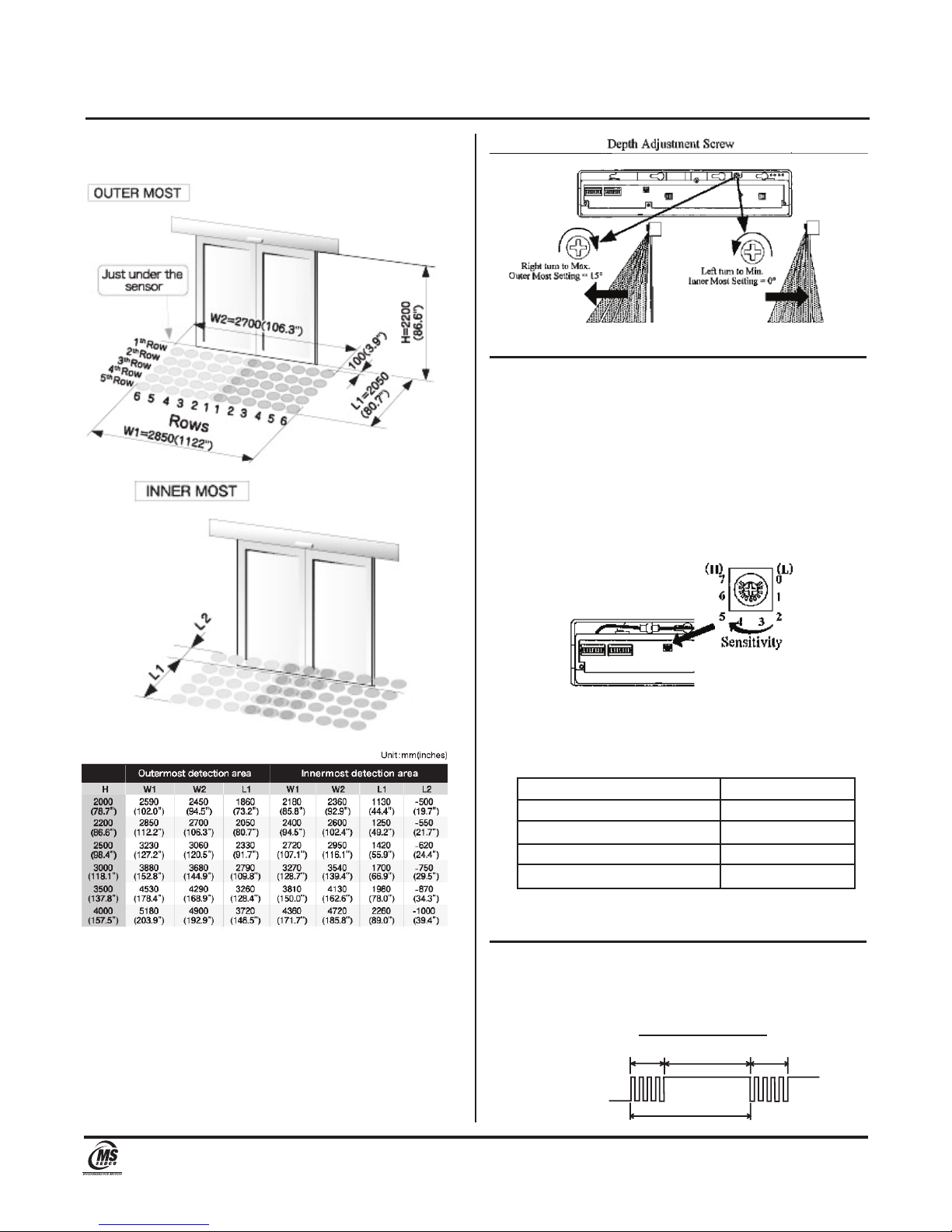
After final set-up, test unit(s) completely to ensure that
proper coverage has been achieved (width, depth and
location of the pattern must be tested).
After the installation and operational check of the
system:
1. Place the proper labels on the door per ANSI/BHMA
A156.10 & BS 7036.
2. Instruct the owner of the door system operation and
how to test it. This should be checked on a daily
basis.
3. Instruct the owner on what to do if the door or any of
its components become damaged.
4. Strongly recommend to the owner that the complete
entry be inspected twice a year as part of the service
agreement.
Section 10
Troubleshooting
PROBLEM 1: Door does not open
LED STATUS: Off
CAUSE 1: Sensor Connector
SOLUTION 1: Tighten connector or reconnect
CAUSE 2: Power Supply
SOLUTION 2: Check that the power supply is properly
connected and 12V to 24V AC or DC
CAUSE 3: Sensor Wiring
SOLUTION 3: Double check sensor wiring.
PROBLEM 2: Door operates by itself (ghosting)
LED STATUS: Door Opens=RED, Door Closes=Green
CAUSE 1: There is an object moving in the
detection area
SOLUTION 1: Remove the moving object from
detection area
CAUSE 2: Sensitivity too high
SOLUTION 2: Turn down sensitivity
CAUSE 3: Dust, frost or water droplet on the
sensor lens
SOLUTION 3: Wipe sensor lens with clean cloth and
install a weather cover if necessary
CAUSE 4: Detection pattern is too far from the
door, detecting people passing by
SOLUTION 4: Adjust detection pattern
CAUSE 5: Detection area overlaps with that of
another sensor
SOLUTION 5: Ensure different frequency setting for
each sensor
CAUSE 6: Detection of falling snow, insects,
leaves, etc.
SOLUTION 6: Adjust the Monitor Mode
PROBLEM 3: When door opens or closes, LED ORANGE
LED STATUS: ORANGE
CAUSE 1: Detection row “ROW 1” (”ROW 2” when
“Doorway Learn” is turned ON) is
focused too close to the door
SOLUTION 1: Adjust detection depth of rows away
from the door
PROBLEM 4: Door opens and remains in the open
position
LED STATUS: RED
CAUSE 1: Detection area changed, while infinity
presence timer setting is in use
SOLUTION 1: Repower the sensor or change the
presence timer settings to 30 or 60
seconds
CAUSE 2: Incorrect Sensor Wiring
SOLUTION 2: Double check sensor wiring
CAUSE 3: Reflected Signal Saturation
SOLUTION 3: Remove highly reflective objects
from the detection area, or lower the
sensor sensitivity
LED STATUS: GREEN/RED FLASH
CAUSE 1: Internal Sensor Error
SOLUTION 1: Replace the sensor
Page 6
DH400v1214
High Mount Active Infrared Presence Detector for Automatic Door Control INSTALLATION INSTRUCTIONS
DH400
8701 Castle Park Drive Indianapolis, Indiana 46256
Telephone: (317) 842-2545 www.mssedco.com custsvc@mssedco.com

Section 11
Technical Data
Model................................ DH400 Presence Detector
Detection Method.............Active Infrared Reflection
Max. Installed Height....... 13.1 ft. (4.0m)
Pattern Adjustments........ Pattern Width
Pattern Depth (up to 6 rows)
Angle Adjustment 0º to 15º
Detection Beams..............16 Beams*5 Rows=60 Beams
Power Supply.................... 12 to 24 V AC or DC ± 10%
Power Consumption......... AC24V-2.5VA, AC12V-2.5VA
DC24V-65mA, DC12V-140mA
Output Contact................. Form C Relay: DC50V 0.1A
(Resistor Load)
Output Holding Time........ Approx. 0.5 seconds
Response Time.................0.1 seconds
Presence Timer.................2 sec., 30 sec., 60 sec., or
infinity (∞)
LED Indication.................. RED = Detecting
GREEN = Standby
GREEN BLINKING - Doorway
Learning (when dip switch Y
8 is ON)
ORANGE = Detection row “ROW
1 (”ROW 2” when “Doorway
Learn” is turned ON) is
detecting door movement
ORANGE BLINKING = Indicates
a change of dip switch settings
or sensitivity volume
GREEN/RED BLINKING =
Internal Sensor Error
IP Rating............................IP54 (with base)
Temperature Range......... -4°F to 140°F
(-20°C to 60°C)
Operating Humidity...........Below 80%
Weight............................... 0.64 lbs. (0.29kg)
Color.................................. Black, Silver
Accessories.......................Cable: 8.2 ft. (2.5m)
Mounting Template
Installation Instructions
Section 12
External Dimensions
Section 13
Warranty
MS SEDCO guarantees this product to be free from manufacturing
defects for 3 years from date of installation. Unless MS SEDCO is
notified of the date of installation, the warranty will be in effect for
3 years from the date of shipment from our factory. If, during the
first 3 years, our motion detector or support device fails to operate
and has not been tampered with our abused, the unit can be
returned prepaid to factory and it will be repaired free of charge.
After 3 years, the unit will be repaired for a nominal service
charge. This limited warranty is in lieu of all other warranties
expressed or implied, including any implied warranty of
merchantability, and no representative or person is authorized
to assume for MS SEDCO any other liability in connection with
the sale of our products. All warranties are limited to the
duration of this written warranty. In no event shall MS SEDCO
be liable for any special, incidental, consequential or other
damages arising from any claimed breach of warranty as to its
products or services.
Page 7
DH400v1214
High Mount Active Infrared Presence Detector for Automatic Door Control INSTALLATION INSTRUCTIONS
DH400
8701 Castle Park Drive Indianapolis, Indiana 46256
Telephone: (317) 842-2545 www.mssedco.com custsvc@mssedco.com

, ,
25mm(O.98")
, I
'-
'
«Bottom
Position
of
Sensor»
1.
Be
sure
to
make
a
hole
for
wiring
within
the
shaded
portion.
{dia
¢
10mm(O.39")}
2.
Be
sure
to
stick
this
mounting
template
with
its
bottom
adjusted
parallel
to
the
same
position
as
the
bottom
edge
of
E
the
engine
cover.
E
E
-f5
Mount
within
50mm(1.97")
above
the
bottom
edge
of
the
engine
cover.
«Bottom
Position
of
Engine
Cover»
Center
l
MOUNTING
TEMPLATE
I SP-10224 I
E
f5
Table of contents
Other MS Sedco Accessories manuals

MS Sedco
MS Sedco INTERSECTOR User manual

MS Sedco
MS Sedco microStar User manual

MS Sedco
MS Sedco DH97 User manual

MS Sedco
MS Sedco SmartWalk XP User manual

MS Sedco
MS Sedco MicroStar blue User manual

MS Sedco
MS Sedco DH100-CT User manual

MS Sedco
MS Sedco ID20 User manual

MS Sedco
MS Sedco INTERSECTOR SDLC User manual

MS Sedco
MS Sedco DH94D User manual
Popular Accessories manuals by other brands

Halo
Halo 5500 user manual

Cooper Controls
Cooper Controls Greengate OEC-U-AF Series installation instructions

SOMFY
SOMFY Sunis WireFree RTS Light Sensor installation guide

Trust
Trust MAIN SOCKET SWITCH AC-3000 manual

Leclerc
Leclerc Wheeled Board instructions

DIEL
DIEL MT300 DIN Installation and instruction manual