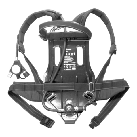
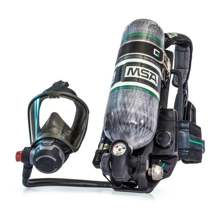
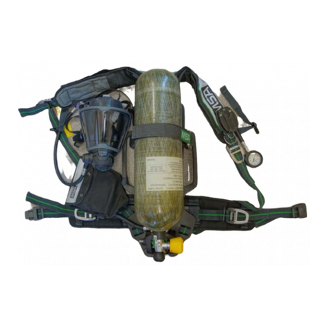
MSA AirGo User manual

MSAsafety.com
Operating Manual
AirGo
Compressed Air Breathing Apparatus - Modular Basic Apparatus
Order No.: 10082058/06

MSA Europe GmbH
Schlüsselstrasse 12
8645 Rapperswil-Jona
Switzerland
Product of Germany
© MSA 2018. All rights reserved

GB
MSA Contents
AirGo 3
Contents
1.Safety Regulations..............................................................................................6
1.1.Correct Use ................................................................................................ 6
1.2.Liability Information .................................................................................... 6
2.Description...........................................................................................................7
2.1.Harness.................................................................................................... 10
2.2.Back Plate ................................................................................................ 12
2.3.Pneumatic System ................................................................................... 13
2.3.1.Pressure Reducer ............................................................................ 13
2.3.2.SingleLine Pneumatics .................................................................... 14
2.3.3.Manifold ........................................................................................... 14
2.3.4.SingleLine SCOUT........................................................................... 14
2.3.4.1.Option – Q – with Quick-Fill Coupling ...........................................15
2.3.4.2.Option – 3C/3N – with Additional Connections for Medium
Pressure........................................................................................16
2.3.4.3.Option – C3 – with Coupling System alphaCLICK 2 .....................17
2.3.4.4.Option – M – with alphaMITTER (short distance transmitter)........19
2.3.5.classic Pneumatics .......................................................................... 20
2.3.5.1.Option – S – with Signal Line ........................................................21
2.3.5.2.Option – Z – with Second Medium Pressure Line .........................22
2.3.5.3.Option – Y – with Second Medium Pressure Line.........................23
2.3.5.4.Option – ICU/ICS – Integrated Control Unit (with or without key)..24
2.3.5.5.Option – C3 – with Coupling System alphaCLICK 2 .....................24
2.3.5.6.Option – M – with alphaMITTER (short distance transmitter)........24
2.3.6.Fix Pneumatics ................................................................................ 25
2.3.6.1.Option – Z .....................................................................................25
2.3.6.2.Option – N.....................................................................................25
2.3.6.3.Option – AE...................................................................................25
2.3.6.4.Option – AS...................................................................................25
3.Using the Compressed Air Breathing Apparatus...........................................26
3.1.Prior to the First Use ................................................................................ 26
3.2.Connecting One Compressed Air Cylinder............................................... 26
3.2.1.Pressure Reducer with Thread Connection ..................................... 26
3.2.1.1.Preparing the Apparatus for Use with One Compressed Air
Cylinder.........................................................................................26
3.2.1.2.Connecting One Compressed Air Cylinder ...................................27
3.2.2.Pressure Reducer with alphaCLICK 2 ............................................. 28
3.2.2.1.Installing Quick Connect Adaptor to Cylinder................................28
3.2.2.2.Connecting One Compressed Air Cylinder ...................................29
3.3.Connecting Two Compressed Air Cylinders............................................. 31
3.3.1.Pressure Reducer with Thread Connection ..................................... 31

GB
Contents MSA
4AirGo
3.3.1.1.Preparing the Apparatus for Use with Two Compressed Air
Cylinders....................................................................................... 31
3.3.1.2.Connecting Two Compressed Air Cylinders ................................. 31
3.3.2.Pressure Reducer with alphaCLICK 2 ............................................. 32
3.4.Donning the Compressed Air Breathing Apparatus.................................. 33
3.5.Condensed Check Prior to Use................................................................ 33
3.6.Donning the Full Face Mask..................................................................... 34
3.7.During Use ............................................................................................... 34
3.8.Use of Additional Connections for Medium Pressure ............................... 35
3.9.Handling the Warning Device................................................................... 35
3.10.Filling with Quick-Fill ................................................................................ 36
3.11.Removing the Compressed Air Breathing Apparatus ............................... 36
3.12.Removing the Compressed Air Cylinders................................................. 37
3.12.1.Pressure Reducer with Thread Connection ..................................... 37
3.12.2.Pressure Reducer with alphaCLICK 2 ............................................. 37
4.Maintenance and Care ......................................................................................39
4.1.Maintenance Instructions ......................................................................... 39
4.2.Maintenance Intervals .............................................................................. 40
4.3.Cleaning................................................................................................... 41
4.3.1.Pre-cleaning..................................................................................... 41
4.3.2.Cleaning, Light Soiling ..................................................................... 41
4.3.3.Cleaning, Heavy Soiling................................................................... 41
4.3.4.Removing the Swivelling Plate......................................................... 43
4.3.5.Cleaning and disinfection of AutoMaXX on Fix pneumatics............. 44
4.4.Changing the Straps and Belt .................................................................. 47
4.4.1.Changing the Shoulder Straps......................................................... 47
4.4.2.Changing the Protection Tunnel ...................................................... 48
4.4.3.Changing the Holder for Mask/Helmet Combination........................ 49
4.4.4.Removing the Rescue Grip.............................................................. 49
4.4.5.Changing the Hip Belt...................................................................... 50
4.4.5.1.Options MaX, eXX and pro with Swivelling Plate .......................... 50
4.4.5.2.Option pro without Swivelling Plate............................................... 51
4.4.5.3.Options com and mix .................................................................... 51
4.4.6.Changing the Cylinder Strap............................................................ 52
4.4.6.1.Long Cylinder Strap ...................................................................... 52
4.4.6.2.Short Cylinder Strap...................................................................... 53
4.4.6.3.alphaBELT und alphaFP............................................................... 53
4.5.Visual, Function and Tightness Check ..................................................... 54
4.6.Checking the Warning Device .................................................................. 54
4.7.Checking the High Pressure Gaskets ...................................................... 54
4.8.Changing the Battery alphaMITTER / alphaSCOUT / ICU....................... 54
4.9.Overhaul................................................................................................... 55

GB
MSA Contents
AirGo 5
4.10.Storage..................................................................................................... 55
4.11.Malfunctions ............................................................................................. 55
5.Compressed Air Cylinders with alphaCLICK 2 ...............................................56
5.1.Changing of Compressed Air Cylinders to alphaCLICK 2........................ 56
5.2.Filling of Compressed Air Cylinders with alphaCLICK 2........................... 57
6.Accessories .......................................................................................................59
6.1.Compressed Air Cylinders........................................................................ 59
6.2.Lung Governed Demand Valves / Full Face Masks ................................. 59
7.Technical Specifications and Certifications....................................................60
8.Notes for Ordering.............................................................................................62
9.Ordering Information.........................................................................................63
9.1.Compressed Air Breathing Apparatus ...................................................... 63
9.2.Lung Governed Demand Valve ................................................................ 63
9.3.Compressed Air Cylinders........................................................................ 64
9.4.Accessories.............................................................................................. 65
9.5.Work Shop Accessories ........................................................................... 66

GB
Safety Regulations MSA
6AirGo
1. Safety Regulations
1.1. Correct Use
The MSA AirGo - referred to hereafter as compressed air breathing apparatus - is
a self-contained breathing apparatus operating independent of the ambient air.
The compressed air breathing apparatus is based on a modular structure which
allows the creation and ordering of a unit matched to the specific requirements.
In combination with a certified facepiece (full face mask) the device protects the
wearer against inhalation of hazardous substances and mixtures, harmful
biological agents and oxygen deficiency.
Breathable air is supplied to the user from a (several) compressed air cylinder(s)
via a pressure reducer, a demand controlled dosage assembly
(Operating Manual for the Lung Governed Demand Valve) and a facepiece
(Operating Manual for the Facepiece). The exhalation air is released directly
into the ambient atmosphere.
It is imperative that this operating manual be read and observed when using the
compressed air breathing apparatus. In particular, the safety instructions, as well
as the information for the use and operation of the apparatus, must be carefully
read and observed. Furthermore, the national regulations applicable in the user's
country must be taken into account for a safe use.
Alternative use, or use outside these specifications will be considered as non-
compliance. This also applies especially to unauthorised alterations to the
apparatus and to commissioning work that has not been carried out by MSA or
authorised persons.
Danger!
This product supports life and health. Inappropriate use, maintenance
or servicing may affect the function of the device and thereby seriously
compromise the user’s life.
Before use, the product operability must be verified. The product must
not be used, if the function test is unsuccessful, it is damaged, a
competent servicing/maintenance has not been made, genuine MSA
spare parts have not been used.
Danger!
This compressed air breathing apparatus is a pure gas protection
device. It is not suitable for underwater diving.
1.2. Liability Information
MSA accepts no liability in cases where the product has been used
inappropriately or not as intended. The selection and use of the product are the
exclusive responsibility of the individual operator.
Product liability claims, warranties also as guarantees made by MSA with respect
to the product are voided, if it is not used, serviced or maintained in accordance
with the instructions in this manual.

GB
MSA Description
AirGo 7
2. Description
Fig. 1 Compressed air breathing apparatus AirGo (here model AirGo pro)
1 Manifold 8 Handle
2 Cylinder separator 9 Stop bracket (U-clip)
3 Cylinder retaining strap 10 Hip belt plate (Option)
4 Cylinder support 11 Quick-Fill coupling (Option)
5 Cylinder buckle 12 Pressure reducer
6 Shoulder strap 13 Pneumatic system (here SingleLine)
7 Back plate 14 Hip belt
The back plate consists of an anatomically designed plate of antistatic plastic with
handles for easy transport of the apparatus. The pressure reducing valve is
located in the lower section of the back plate. On the upper part of the back plate,
a cylinder support is attached with integrated line guide.
The carrying belts and the hip belt are adjustable in length.
One or two compressed air cylinders can be placed in the cylinder support. The
cylinder strap is freely adjustable and after inserting the compressed air
cylinder(s), it is tightened and secured using the cylinder buckle.
The structure of the compressed air breathing apparatus is based on a modular
design. This allows the user to configure the compressed air breathing apparatus
from the modules available to match his specific requirements.
5
6
1
2
7
8
9
10111314
3 4
1
2

GB
Description MSA
8AirGo
The following options are available:
Harness options com - compact basic harness with polyester
straps
(Section 2.1) pro - padded harness
mix
- hip belt as compact and shoulder
straps as pro
MaX
- premium harness
eXX
- eXXtreme, for training
BSP
- premium harness with protection
tunnel
FBS
alphaFP basic
FBL
alphaFP basic large
FPS
alphaFP PRO
FPL
alphaFP PRO large
ABP
alphaBELT PRO Basic
APP
alphaBELT PRO PRO
ABM
alphaBELT MAX Basic
APM
alphaBELT MAX PRO
Back plate options B - bumper
V
- bumper with valve-protection
(Section 2.2) LG, SH - cylinder retaining straps (long or short)
SW - swivelling hip plate
(standard for harness options MaX
and eXX, optional for pro)
R - retainer
H - rescue grip and retainer

GB
MSA Description
AirGo 9
Pneumatic system
Pressure reducer SingleLine – for use in SingleLine pneumatics
(Section 2.3.1) classic – for use in classic pneumatics
SingleLine SL
- “hose-in-hose”, with manifold
(Section 2.3.2) SI - with SingleLine SCOUT instead of
gauge 1 medium pressure coupling
SII with SingleLine SCOUT instead of
gauge 2 medium pressure coupling
Q - with additional quick-fill coupling
M - with alphaMITTER
(short distance transmitter)
3C/3N - with additional medium pressure
connection
C3 - with coupling system alphaCLICK 2
(300 bar)
classic pneumatics
(Section 2.3.5)
CL -
with separate high pressure and
medium pressure lines and pressure
gauge
CM - with separate high pressure and
medium pressure lines and pressure
gauge, retrofit with alphaMITTER
S - with signal line
Z - with second medium pressure
connection
Y - with second medium pressure
connection (laid over the shoulder)
ICU/ICS - with integrated control unit
C3 - with coupling system alphaCLICK 2
M - with alphaMITTER
(short distance transmitter),
only with CM
Fix pneumatics
(Section 2.3.6)
as classic with fixed lung governed demand valve
(AE, AS, N, optional gauge cap) without coupling

GB
Description MSA
10 AirGo
2.1. Harness
There are different types of harness (shoulder and hip belt) available, each
having different properties and carrying comfort:
com – basic harness
This is the basic harness. Shoulder strap and hip belt made of flame retardant
polyester material with no additional padding.
pro – padded harness
Shoulder strap and hip belt made of Aramide reinforced material with
additional padding (NOMEX®). The shoulder padding and the hip belt ensure
effective weight distribution and offer high levels of carrying comfort.
Optionally, the hip belt is mounted on a swivelling plate (Section 2.2).
mix – mixed harness
Shoulder strap made of Aramide reinforced material with additional padding
(NOMEX®) as in type pro.
The hip belt is made of flame retarded polyester material with no additional
padding as in type com.
MaX – premium harness
Shoulder straps and hip belt are made of Aramide reinforced material and
have additional padding with the shoulder straps being performed in an
S-shape. The harness offer high levels of carrying comfort.
The hip belt is swivelling mounted (Section 2.2) and is known from the
AirMaXX®breathing apparatus.
eXX – eXXtreme harness
The eXXtreme harness is based on the tried and tested AirMaXX®. The straps
and belt are made from Aramide fibre and are particularly robust and fire-
resistant. Protective sleeves in the shoulder padding protect the lines from
flame and heat.
The harness is specially suited to repeated extreme demands in training
situations, such as in flashover training, for example.
BSP – premium harness
This premium harness is a combination of the premium harness MaX and the
eXXtreme harness eXX.
The protective sleeves are fixed on the one side with a “pull the dot” button
and on the other side with a double button.
The frangible mounting with double buttons ensures a quick pulling out of an
additional medium pressure line for supplying a second person with
breathing air.
This premium harness has additional ribbons to attach a mask/helmet
combination.

GB
MSA Description
AirGo 11
FP Fall Arrest
Solid stainless steel rings serve as attachment points for fall arrest lanyards.
Positioning: D-rings on each side of the hip belt allow for safe positioning on
an exposed work site.
Rappelling: Prolonged operations on a rope can be conducted in comfort, as
the hip harness with both leg loops turns into a comfortable seat. By virtue of
its slide-through design, normal walking is unobstructed.
Rescue: The back D-ring can be used for safe rescue from confined space.
alphaFP pro additionally features hose protection tunnels on shoulder pads
and quick connect buckles between harness and SCBA for ease of mounting
or emergency removal during operation.
Belt
The comfortable alphaBELT Pro is the optimal configuration. Compared to the
alphaBELT Basic it includes:
Versatile alphaBELT Lanyard
Safe rescue seat function
Quick connect buckles for SCBA (separating function)
Elastic fixation for overhanging strap ends
To build the rescue seat (EN 1498, class B), an additional rappelling carabiner
(according to EN 362) is required in the front loop of the belt. For this purpose
MSA recommends the MSA steel Tri-Lock carabiner, tested and approved for
use with an SCBA. It is an optional accessory and not included.

GB
Description MSA
12 AirGo
2.2. Back Plate
Cylinder straps
There are cylinder straps of different lengths for securing one or two compressed
air cylinders.
Short cylinder strap (SH) - for use with one compressed air cylinder
(from 4 l to 6.9 l)
Long cylinder strap (LG) - for use with one or two compressed air cylin-
der(s) (for one cylinder from 4 l to 9 l, for two cylinders from 4 l to 6.9 l)
Bumper (B)
The bumper is made out of hard-wearing rubber and mounted on the bottom of
the back plate. It prevents the apparatus from being damaged in the event that it
is put down heavily.
Bumper with valve-protection (V)
The bumper is made out of hard-wearing rubber and mounted on the bottom of
the back plate. The valve protection prevents the valve from being damaged in
the event that it is put down heavily.
Hip belt plate (SW)
The swivelling hip belt plate is mounted on the bottom of the back plate and is
used to support the hip belt.
The hip belt can be swivelled and thus follows all movements made by the
equipment user. The swivel range is limited and the cushioned reset movement
increases the feeling of safety.
For models MaX and eXX the swivelling hip belt plate is standard equipment and
for the pro model it is available as an option.
Cylinder retainer (R)
The elastic cylinder retainer serves to increase friction between cylinder and back
plate.
Rescue grip and retainer (H)
The rescue grip is used for drawing out persons and can be used for easy
transport of the apparatus.
Separator (D)
Metal bracket to divide two cylinders to facilitate mounting of two cylinders and
give guidance to cylinder strap.
Transponder
The back plate is equipped with a 125 kHz transponder (RFID chip) next to the
label for easy identification.

GB
MSA Description
AirGo
13
2.3. Pneumatic System
2.3.1. Pressure Reducer
Fig. 2 Pressure reducer classic
1 Pressure reducer
2 Cylinder connection
3 Signal line
4 High pressure line
5 Medium pressure line
Fig. 3 Pressure reducer SingleLine
1 Single line
2 Cylinder connection
3 Quick-Fill coupling (Option)
The pressure reducer is mounted in the lower area of the back plate (Fig. 1). It
is available in both classic and SingleLine pneumatic versions.
On the pressure reducer, there is a safety valve and the single line for connecting
the manifold. The pressure reducer reduces the cylinder pressure to
approx. 7 bar and the safety valve activates on non-permitted pressure rise to
prevent damage insuring the continued supply of breathable air.
1
5 4 3
2
1
2
3

GB
Description MSA
14 AirGo
2.3.2. SingleLine Pneumatics
SingleLine pneumatics are available in options -Q, -M, -SI, -SII, -3C/3N, -C3.
The SingleLine pneumatics combines up to five hoses in one. This incorporates
the lines for the lung governed demand valve, the pressure gauge, warning signal
and second connection in a single line.
2.3.3. Manifold
Fig. 4 Manifold
1 Pressure gauge 3 Warning signal (signal whistle)
2 Lung governed demand valve coupling 4 Second connection
In SingleLine Pneumatics, the end of the single line is connected to manifold. It
consists of the pressure gauge itself, the coupling for the lung governed demand
valve as well as an acoustic warning device (signal whistle). It triggers a
continuous warning signal when the cylinder pressure drops below 55±5 bar.
The second connection connects a second lung governed demand valve
(e.g. rescue set).
2.3.4. SingleLine SCOUT
See additional manual SingleLine SCOUT.
4
1
3
2

GB
MSA Description
AirGo 15
2.3.4.1. Option – Q – with Quick-Fill Coupling
Fig. 5 Pressure reducer SingleLine
1 Single line
2 Cylinder connection
3 Quick-Fill coupling
The Quick-Fill coupling is a high-pressure safety coupling which is fitted directly
on the pressure reducer (Fig. 2).
It is then possible to fill 300 bar compressed air cylinder(s) whilst the compressed
air breathing apparatus is still donned. The connector of the pressure reducer is
arranged so that a 200 bar compressed air cylinder cannot be connected in order
to avoid inadvertent overfilling.
On compressed air breathing apparatus with Quick-Fill couplings, the
use of 200 bar compressed air cylinders is not possible.
For further information please observe the separate Operation Manual
for the Quick-Fill System (Part No. D4075049).
1
2
3

GB
Description MSA
16 AirGo
2.3.4.2. Option – 3C/3N – with Additional Connections for Medium Pressure
The compressed air breathing apparatus can be equipped with additional
connections for medium pressure. These are located on the hip belt and are used
for the connection of additional units such as, for example, a second lung
governed demand valve or a rescue hood.
Fig. 6 Option SL-3C
1 Pressure reducer 3 Additional medium pressure line
2 Single line 4 Coupling for third connection
There is an additional medium pressure connection on the hip belt of the
compressed air breathing apparatus which is available as a coupling in option 3C
and as a nipple with integrated non-return valve in option 3N.
Option 3C is provided for the connection of the following units, under
consideration of the specific national regulations:
Rescue set (mask with lung governed demand valve)
Rescue equipment e.g. Respihood
Compressed air line equipment with or without automatic switch valve
and for use in a protective suit during decontamination process.
Warning!
When rescuing persons with the rescue set via the second connection,
more air is consumed.
Hence, the service time is considerably reduced. Always keep this in
mind when using your apparatus.
Option 3N is prepared for the connection of the following equipment:
Compressed Breathing Apparatus without automatic switch valve
and for use in a protective suite including decontamination process.
4
2
1
3

GB
MSA Description
AirGo
17
2.3.4.3. Option – C3 – with Coupling System alphaCLICK 2
Fig. 7 Pressure reducer
1 al
p
haCLICK 2 cou
p
lin
g
The alphaCLICK 2 coupling system permits the easy, quick and safe connection
of the compressed air cylinders to the pressure reducer. Time-consuming
threading-on of the cylinder is no longer required since the cylinder is simply
slotted into the pressure reducer.
alphaCLICK 2 is safer than the usual standard connection:
alphaCLICK 2 cannot be disconnected when the system is pressurised.
Two steps are required to disconnect it: the cylinder can only be removed
when the coupling handwheel has been turned by 20 degrees and
pushed back.
alphaCLICK 2 has no built-in flow restrictor.
Moreover, alphaCLICK 2 has a flat face design which keeps the
components clean and operative.
alphaCLICK 2 fits all standard breathable air valve threads [EN 144-2].
alphaCLICK 2 is only available for 300 bar:
1

GB
Description MSA
18
AirGo
alphaCLICK 2 coupling 300 bar
Fig. 8 alphaCLICK 2 coupling 300 bar
1 alphaCLICK 2 coupling 300 bar
2 Indicator ring with arrow
alphaCLICK 2 cylinder adaptor 300 bar
Fig. 9 alphaCLICK 2 cylinder adaptor 300 bar
1 alphaCLICK 2 cylinder adaptor 300 bar
The cylinder adaptor has to be screwed into a cylinder valve with a
specific torque of 20-30 Nm.
1
2
1

GB
MSA Description
AirGo 19
2.3.4.4. Option – M – with alphaMITTER (short distance transmitter)
Fig. 10 alphaMITTER
1 Back plate 3 High pressure line
2 alphaMITTER 4 Pressure reducer
The alphaMITTER is a short range transmitter which is mounted on the back
plate of the compressed air breathing apparatus.
A high pressure line is used for the connection of the alphaMITTER to a
dedicated port of the pressure reducer. It measures the high pressure in the
compressed air cylinder(s) and transmits every second to the alphaSCOUT of the
alpha personal network.
The power supply for the alphaMITTER is provided by 3 Alkaline batteries.
Attention!
The power supply should only be provided by certain types of battery
for reasons of explosion prevention.
For detailed information on the alphaMITTER Operating Manual for
"alpha personal network".
2
1
4 3

GB
Description MSA
20
AirGo
2.3.5. classic Pneumatics
Option – CL
classic pneumatics are available in options -S, -Z, -ICU, -C3.
The individual high pressure and medium pressure lines are routed separately
from the pressure reducer to the individual end units or connections.
The lung governed demand valve or the coupling to the lung governed demand
valve is located at the end of the medium pressure line.
The pressure gauge (Fig. 11) or the ICU (Fig. 15) is fitted at the end of the
high pressure line.
Fig. 11 Pressure gauge
The pressure gauge indicates the momentary pressure in the connected and
opened compressed air cylinders.
Option – CM
The option CM of the classic pneumatics has the same basic
characteristics as the CL option, but can be operated with an
alphaMITTER.
Table of contents
Other MSA Diving Instrument manuals

MSA
MSA AirElite 4h User manual

MSA
MSA 10050038 User manual

MSA
MSA AirHawk II Setup guide

MSA
MSA FireHawk 10025120 Quick start guide

MSA
MSA AUER Atemluft 300 bar User manual

MSA
MSA PremAire Combination Series User manual

MSA
MSA G1 SCBA User manual

MSA
MSA alpha Series User manual

MSA
MSA AirElite 4h User manual