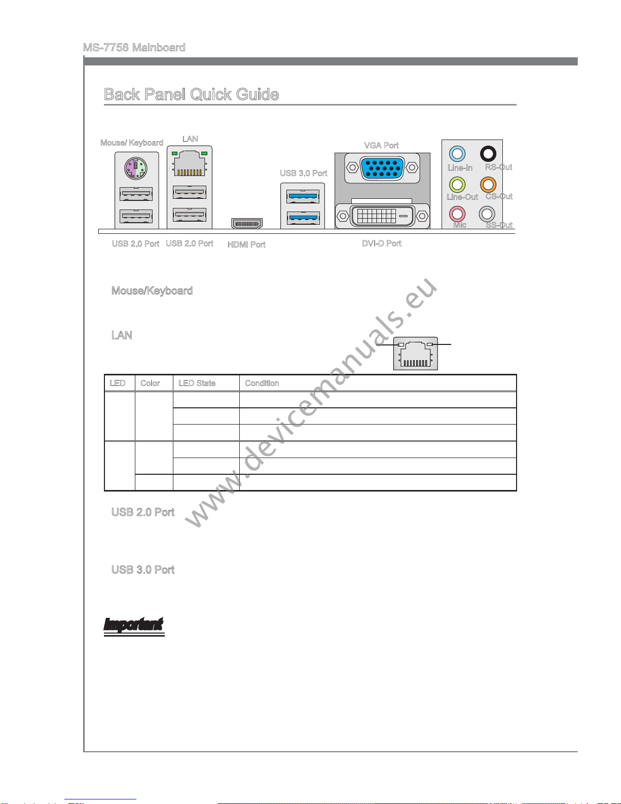
MSI B75A-G43 series User manual

B75A-G43 seres
MS-7758 (v2.x) Manboard
G52-77581X5
Europe verson
www.devicemanuals.eu

Englsh
B75A-G43 Seres
www.devicemanuals.eu

En-2
MS-7758 Manboard
Manboard Speccatons
Processor Support
Support 3rd Generaton Intel® Core™ 7/ Core™ 5/ Core™ 3/ Pentum®/ Celeron®
Processors for LGA 1155 socket
(For the latest nformaton about CPU, please vst
http://www.ms.com/servce/cpu-support)
Chpset
Intel® B75 chpset
Memory Support
4x DDR3 DIMMs support DDR3 1600/ 1333/ 1066 DRAM (32GB Max.)
Supports Dual-Channel mode, two DIMMs per channel
(For the latest nformaton about memory, please vst
http://www.ms.com/servce/test-report)
LAN
Supports LAN 10/100/1000 Fast Ethernet by Realtek® RTL8111E
Audo
Integrated HD audo codec by Realtek® ALC892
8-channel audo wth jack sensng
SATA
1x SATA 6Gb/s port (SATA1) by Intel® B75
5x SATA 3Gb/s ports (SATA2~6) by Intel® B75
USB 3.0
2x USB 3.0 rear IO ports by Intel® B75
1x USB 3.0 onboard connector by Intel® B75
Mult-GPU
Supports AMD® CrossFre™ Technology
■
■
■
■
■
■
■
■
■
■
■
■
www.devicemanuals.eu

En-3
Englsh
Connectors
Back panel
1x PS/2 keyboard/ mouse combo port
4x USB 2.0 ports
2x USB 3.0 ports
1x LAN port
1x HDMI port**, supportng a maxmum resoluton of 1920x1200
1x VGA port**
1x DVI-D port**, supportng a maxmum resoluton of 1920x1200
6x audo ports
(**Ths manboard supports dual-dsplay functon by any two onboard graphcs output
ports (HDMI+DVI,DVI+VGA or VGA+HDMI)).
On-Board
2x USB 2.0 connectors
1x USB 3.0 connector
1x TPM Module connector
1x Seral Port connector
1x Parallel Port connector
1x Front Panel Audo connector
1x Chasss Intruson connector
1x Voce Gene connector (optonal)
Slots
1x PCIe 3.0 x16 slot, PCI_E2, t supports up to PCIe 3.0 x16 speed
1x PCIe 2.0 x16 slot, PCI_E4, t supports up to PCIe 2.0 x4 speed
2x PCIe 2.0 x1 slots
3x PCI slots
Form Factor
ATX (30.5 cm X 24.4 cm)
Mountng Screw Holes
9x mountng holes
■-
-
-
-
-
-
-
-
■-
-
-
-
-
-
-
-
■
■
■
■
■
■
If you need to purchase accessores and request the part numbers, you could search
the product web page and nd detals on our web address http://www.ms.com/ndex.
php
www.devicemanuals.eu

En-4
MS-7758 Manboard
Connectors Quck Gude
Back Panel
CPU
CPUFAN
DIMM1
JPWR2
JPWR1
SATA1/ 2
JFP2
JAUD1
JCI1
JDLED3
PCI_E1
SYSFAN1
JBAT1
SYSFAN3
JCOM1
PCI_E2
PCI_E3
PCI_E4
JFP1
JTPM1
JUSB3
JUSB1/ 2
SATA3/ 4
SATA5/ 6
JLPT1
DIMM2
DIMM3
DIMM4
SYSFAN2
SYSFAN4
PCI1
PCI2
PCI3
www.devicemanuals.eu

En-5
Englsh
Connectors Reference Gude
Port Name Port Type Page
Back Panel I/O Ports En-6
CPU LGA 1155 CPU Socket En-9
CPUFAN,SYSFAN1~4 Fan Power Connectors En-19
DIMM1~4 DDR3 Memory Slots En-14
JAUD1 Front Panel Audo Connector En-23
JBAT1 Clear CMOS Jumper En-25
JCI1 Chasss Intruson Connector En-22
JCOM1 Seral Port Connector En-24
JDLED3 Voce Gene Connector En-25
JFP1, JFP2 Front Panel Connectors En-20
JLPT1 Parallel Port Connector En-24
JPWR1 ATX 24-pn Power Connector En-13
JPWR2 ATX 8-pn Power Connector En-13
JTPM1 TPM Module Connector En-23
JUSB1~2 USB 2.0 Expanson Connectors En-22
JUSB3 USB 3.0 Expanson Connector En-21
PCI1~3 PCI Expanson Slots En-17
PCI_E2, PCI_E4 PCIe x16 Expanson Slots En-16
PCI_E1, PCI_E3 PCIe x1 Expanson Slots En-16
SATA1 SATA 6Gb/s Connector En-18
SATA2~6 SATA 3Gb/s Connectors En-18
www.devicemanuals.eu

En-6
MS-7758 Manboard
Back Panel Quck Gude
Mouse/Keyboard
A combnaton PS/2® mouse/keyboard DIN connector for a PS/2® mouse/keyboard.
LAN
The standard RJ-45 LAN jack s for connectng to
a Local Area Network (LAN).
LED Color LED State Condton
Left Yellow O LAN lnk s not establshed.
On(Steady) LAN lnk s establshed.
On(ashng) The computer s communcatng wth another computer on the network.
Rght Green O 10 Mbts/sec data rate
On 100 Mbts/sec data rate
Orange On 1000 Mbts/sec data rate
USB 2.0 Port
The USB 2.0 port s for attachng USB 2.0 devces such as keyboard, mouse, or other
USB 2.0-compatble devces.
USB 3.0 Port
USB 3.0 port s backward-compatble wth USB 2.0 devces. It supports data transfer
rate up to 5 Gbt/s (SuperSpeed).
Important
In order to use USB 3.0 devces, you must connect to a USB 3.0 port. If a USB cable s
used, t must be USB 3.0 complant.
▶
▶
▶
▶
Yellow Green/ Orange
Lne-In
Lne-Out
Mc
RS-Out
CS-Out
SS-Out
USB 3.0 Port
LAN
Mouse/ Keyboard
USB 2.0 Port
VGA Port
DVI-D Port
USB 2.0 Port HDMI Port
www.devicemanuals.eu

En-7
Englsh
HDMI Port
The Hgh-Denton Multmeda Interface (HDMI) s an all-dgtal audo-vdeo nterface
that s capable of transmttng uncompressed streams. HDMI supports all types of TV
formats, ncludng standard, enhanced, or hgh-denton vdeo, plus mult-channel
dgtal audo on a sngle cable.
VGA Port
The DB15-pn female connector s provded for montor.
DVI-D Port
The DVI-D (Dgtal Vsual Interface- Dgtal) connector can be connected to a LCD
montor, or a CRT montor wth an adapter. To connect a montor, please refer to the
montor’s manual for more nformaton.
Important
Ths platform supports dual-dsplay functon by any two output ports (HDMI+DVI,
DVI+VGA or VGA+HDMI).
HDMI+DVI DVI+VGA VGA+HDMI
Extend mode
(Extend the desktop to the second montor) ◯◯◯
Clone mode
(Two montors have the same screen) ◯◯◯
Audo Ports
These connectors are used for audo devces. The color of the jack refers to the functon
of the connector.
Blue-Lne n: Used for connectng external audo outputtng devces.
Green- Lne out: Used as a connector for speakers or headphone.
Pnk- Mc: Used as a connector for a mcrophone.
Black- RS-Out: Rear surround sound lne out n 4/ 5.1/ 7.1 channel mode.
Orange- CS-Out: Center/ subwoofer lne out n 5.1/ 7.1 channel mode.
Gray- SS-Out: Sde surround sound lne out n 7.1 channel mode.
▶
▶
▶
▶
■
■
■
■
■
■
www.devicemanuals.eu

En-8
MS-7758 Manboard
CPU (Central Processng Unt)
Introducton to the LGA 1155 CPU
The surface of the LGA 1155 CPU
has two algnment keys and a
yellow trangle to assst n correctly
lnng up the CPU for manboard
placement. The yellow trangle s the
Pn 1 ndcator.
Yellow trangle s the
Pn 1 ndcator
Algnment Key
Important
Overheatng
Overheatng can serously damage the CPU and manboard. Always make sure the
coolng fans work properly to protect the CPU from overheatng. Be sure to apply an
even layer of thermal paste (or thermal tape) between the CPU and the heatsnk to
enhance heat dsspaton.
Replacng the CPU
When replacng the CPU, always turn o the system’s power supply and unplug the
power supply’s power cord to ensure the safety of the CPU.
Overclockng
Ths manboard s desgned to support overclockng. Before attemptng to overclock,
please make sure that all other system components can tolerate overclockng. Any
attempt to operate beyond product speccatons s not recommend. MSI does not
guarantee the damages or rsks caused by nadequate operaton beyond product
speccatons.
www.devicemanuals.eu

En-9
Englsh
CPU & Cooler Installaton
When nstallng a CPU, always remember to nstall a CPU cooler. A CPU cooler s
necessary to prevent overheatng and mantan system stablty. Follow the steps below
to ensure correct CPU and CPU cooler nstallaton. Wrong nstallaton can damage both
the CPU and the manboard.
Unhook and lft the loadng lever to
the fully open poston.
1. The loadng plate should
automatcally lft up as the loadng
lever s pushed to the fully open
poston. Do not touch any of the
CPU socket pns.
2.
Lne up the CPU to t the CPU
socket. Be sure to hold the CPU by
the base wth the metal contacts
facng downward. The algnment
keys on the CPU wll lne up wth the
edges of the CPU socket to ensure a
correct t.
3. Close the loadng plate and remove
the plastc protectve cap.
4.
Algnment Key
www.devicemanuals.eu

En-10
MS-7758 Manboard
Inspect the CPU to check f t s
properly seated n the socket. Press
the loadng lever down and lock t
under the retenton tab.
5. Evenly spread a thn layer of
thermal paste (or thermal tape) on
the top of the CPU. Ths wll help n
heat dsspaton and prevent CPU
overheatng.
6.
Locate the CPU fan connector on the
manboard.
7. Place the heatsnk on the manboard
wth the fan’s wres facng towards the
fan connector and the hooks matchng
the holes on the manboard.
8.
www.devicemanuals.eu

En-11
Englsh
Important
Do not touch the CPU socket pns.
Conrm that the CPU cooler has formed a tght seal wth the CPU before bootng
your system.
Whenever the CPU s not nstalled, always protect the CPU socket pns by coverng
the socket wth the plastc cap.
Please refer to the documentaton n the CPU cooler package for more detals about
CPU cooler nstallaton.
•
•
•
•
Push down on the heatsnk untl the
four clps get wedged nto the holes
on the manboard. Press the four
hooks down to fasten the cooler. As
each hook locks nto poston a clck
should be heard.
9. Inspect the manboard to ensure that
the clp-ends have been properly
locked n place.
10.
Fnally, attach the CPU fan cable
to the CPU fan connector on the
manboard.
11.
Manboard
Hook
www.devicemanuals.eu

En-12
MS-7758 Manboard
Mountng Screw Holes
When nstallng the manboard, rst nstall the necessary mountng stands requred for
a manboard on the mountng plate n your computer case. If there s an I/O back plate
that came wth the computer case, please replace t wth the I/O backplate that came
wth the manboard package. The I/O backplate should snap easly nto the computer
case wthout the need for any screws. Algn the mountng plate’s mountng stands wth
the screw holes on the manboard and secure the manboard wth the screws provded
wth your computer case. The locatons of the screw holes on the manboard are shown
below. For more nformaton, please refer to the manual that came wth the computer
case.
Important
Install the manboard on a at surface free from unnecessary debrs.
To prevent damage to the manboard, any contact between the manboard crcutry
and the computer case, except for the mountng stands, s prohbted.
Please make sure there are no loose metal components on the manboard or wthn
the computer case that may cause a short crcut of the manboard.
•
•
•
The I/O ports should be facng toward
the rear of the computer case. They
should lne up wth the holes on the
I/O backplate.
www.devicemanuals.eu

En-13
Englsh
Power Supply
JPWR1: ATX 24-pn Power Connector
Ths connector allows you to connect an ATX 24-pn power supply. To connect the ATX
24-pn power supply, algn the power supply cable wth the connector and rmly press
the cable nto the connector. If done correctly, the clp on the power cable should be
hooked on the manboard’s power connector.
13.+3.3V
1.+3.3V
14.-12V
2.+3.3V
15.Ground
3.Ground
16.PS-ON#
4.+5V 17.Ground
5.Ground
18.Ground
6.+5V
19.Ground
7.Ground
22.+5V
10.+12V
20.Res
8.PWR OK
23.+5V
11.+12V
21.+5V
9.5VSB
24.Ground
12.+3.3V
JPWR2: ATX 8-pn Power Connector
Ths connector provdes 12V power to the CPU.
7.+12V
3.Ground
5.+12V
1.Ground
8.+12V
4.Ground
6.+12V
2.Ground
Important
Make sure that all the power cables are securely connected to a proper ATX power
supply to ensure stable operaton of the manboard.
www.devicemanuals.eu

En-14
MS-7758 Manboard
Memory
These DIMM slots are used for nstallng memory modules. For more nformaton on
compatble components, please vst http://www.ms.com/servce/test-report
DDR3
240-pn, 1.5V
48x2=96 pn 72x2=144 pn
Dual-Channel mode Populaton Rule
In Dual-Channel mode, the memory modules can transmt and receve data wth two
data bus channels smultaneously. Enablng Dual-Channel mode can enhance system
performance. The followng llustratons explan the populaton rules for Dual-Channel
mode.
1 DIMM1
DIMM2
DIMM3
DIMM4
2 DIMM1
DIMM2
DIMM3
DIMM4
Important
DDR3 memory modules are not nterchangeable wth DDR2, and the DDR3 standard
s not backward compatble. Always nstall DDR3 memory modules n DDR3 DIMM
slots.
To ensure system stablty, memory modules must be of the same type and densty
n Dual-Channel mode.
Due to chpset resource usage, the system wll only detect up to 31+ GB of memory
(not full 32 GB) when all DIMM slots have 8GB memory modules nstalled.
•
•
•
Installed
Empty
www.devicemanuals.eu

En-15
Englsh
Installng Memory Modules
Unlock the DIMM slot by pushng the mountng clps to the sde. Vertcally nsert the
memory module nto the DIMM slot. The memory module has an o-center notch on
the bottom that wll only allow t to t one way nto the DIMM slot.
Push the memory module deep nto the DIMM slot. The plastc clps at each sde
of the DIMM slot wll automatcally close when the memory module s properly seat
and an audble clck should be heard.
Manually check f the memory module has been locked n place by the DIMM slot’s
sde clps.
1.
2.
3.
Notch
Volt
www.devicemanuals.eu

En-16
MS-7758 Manboard
Expanson Slots
Ths manboard contans numerous ports for expanson cards, such as dscrete graphcs
or audo cards.
PCIe (Perpheral Component Interconnect Express) Slot
The PCIe slot supports the PCIe nterface expanson card.
PCIe 2.0 x16 Slot
PCIe 2.0 x1 Slot
PCIe 3.0 x16 Slot
www.devicemanuals.eu

En-17
Englsh
PCI (Perpheral Component Interconnect) Slot
The PCI slot supports addtonal LAN, SCSI, USB, and other add-on cards that comply
wth PCI speccatons.
32-bt PCI Slot
Important
When addng or removng expanson cards, always turn o the power supply and
unplug the power supply power cable from the power outlet. Read the expanson card’s
documentaton to check for any necessary addtonal hardware or software changes.
PCI Interrupt Request Routng
IRQ, or nterrupt request lnes, are hardware lnes over whch devces can send nterrupt
requests to the processor. The PCI IRQ pns are typcally connected to the PCI bus pns
as followed:
Order1 Order2 Order3 Order4
PCI Slot1 INT A# INT B# INT C# INT D#
PCI Slot2 INT B# INT C# INT D# INT A#
PCI Slot3 INT C# INT D# INT A# INT B#
www.devicemanuals.eu

En-18
MS-7758 Manboard
Internal Connectors
SATA1~6: SATA Connector
Ths connector s a hgh-speed SATA nterface port. Each connector can connect to one
SATA devce. SATA devces nclude dsk drves (HDD), sold state drves (SSD), and
optcal drves (CD/ DVD/ Blu-Ray).
* The MB layout n ths gure s for reference only.
SATA1 (6Gb/s)
SATA2~6 (3Gb/s)
SATA1
SATA2
SATA3
SATA4
SATA5
SATA6
Important
Many SATA devces also need a power cable from the power supply. Such devces
nclude dsk drves (HDD), sold state drves (SSD), and optcal drves (CD / DVD /
Blu-Ray). Please refer to the devce’s manual for further nformaton.
Many computer cases also requre that large SATA devces, such as HDDs, SSDs,
and optcal drves, be screwed down nto the case. Refer to the manual that came
wth your computer case or your SATA devce for further nstallaton nstructons.
Please do not fold the SATA cable at a 90-degree angle. Data loss may result durng
transmsson otherwse.
SATA cables have dentcal plugs on ether sdes of the cable. However, t s
recommended that the at connector be connected to the manboard for space
savng purposes.
•
•
•
•
www.devicemanuals.eu

En-19
Englsh
CPUFAN,SYSFAN1~4: Fan Power Connectors
The fan power connectors support system coolng fans wth +12V. If the manboard has
a System Hardware Montor chpset on-board, you must use a specally desgned fan
wth a speed sensor to take advantage of the CPU fan control. Remember to connect
all system fans. Some system fans may not connect to the manboard and wll nstead
connect to the power supply drectly. A system fan can be plugged nto any avalable
system fan connector.
SYSFAN3/ SYSFAN4
1.Ground
2.FAN Voltage
3.Sensor/ No Use
1.Ground
2.+12V
3.Sensor
4.Control
CPUFAN
1.Ground
2.Control
3.Sensor
4.No use
SYSFAN1/ SYSFAN2
Important
Please refer to your processor’s ocal webste or consult your vendor to nd
recommended CPU coolng fans.
The CPUFAN connector supports Smart Fan Control wth lnear mode. The Control
Center II utlty can be nstalled to automatcally control the fan speeds accordng to
the CPU’s temperature.
If there are not enough ports on the manboard to connect all system fans, adapters
are avalable to connect a fan drectly to a power supply.
Before rst boot up, ensure that there are no cables mpedng any fan blades.
•
•
•
•
www.devicemanuals.eu
Table of contents
Other MSI Motherboard manuals

MSI
MSI MS-7596 (v1.x) User manual

MSI
MSI Z77IA-S01 Series User manual

MSI
MSI MS-6533E User manual

MSI
MSI MAG B550M MORTAR WIFI User manual

MSI
MSI MS-98F3 User manual

MSI
MSI 611BF User manual

MSI
MSI PRO B760M-G DDR4 User manual

MSI
MSI MEG Z390 ACE User manual

MSI
MSI MS-7160 User manual

MSI
MSI MPG B560I User manual

MSI
MSI B550M PRO-VDH WIFI User manual

MSI
MSI D3050 User manual

MSI
MSI B450M MORTAR MAX User manual

MSI
MSI 785G-E65 Series User manual

MSI
MSI 661FM3-L User manual

MSI
MSI Z370 GAMING PRO CARBON User manual

MSI
MSI H61MU-E35 series User manual

MSI
MSI MS-6188 User manual

MSI
MSI 970A-G46 Series User manual

MSI
MSI P35 Diamond MS-7356 User manual