CHAPTER 2CHAPTER 2
CHAPTER 2CHAPTER 2
CHAPTER 2 HARDHARD
HARDHARD
HARDWW
WW
WARE INSTARE INST
ARE INSTARE INST
ARE INSTALLAALLA
ALLAALLA
ALLATIONTION
TIONTION
TION
2-9
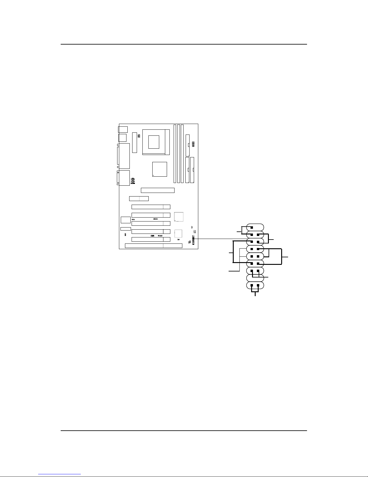
2.4-1 Power Switch
Connect to a 2-pin push button switch. This switch has the same feature
with JRMS1.
2.4-2 Reset Switch
Reset switch is used to reboot the system rather than turning the power ON/
OFF. Avoid rebooting while the DD LED is lit. You can connect the Reset
switch from the system case to this pin.
2.4-3 Power LED
The Power LED is lit while the system power is on. Connect the Power LED
from the system case to this pin. There are two types of LED that you can
use: 3-pin single color LED or 2-pin dual color LED(ACPI request).
a. 3 pin single color LED connect to pin 4, 5, & 6. This LED will lit
when the system is on.
b. 2 pin dual color LED connect to pin 5 & 6.
GREEN Color: Indicate the system is in full on mode.
ORANGE Color: Indicate the system is in suspend mode.
2.4-4 Speaker
Speaker from the system case is connected to this pin.
If on-board Buzzer is available:
Short pin 14-15: On-board Buzzer Enabled.
Open pin 14-15: On-board Buzzer Disabled.
2.4-5 HDD LED
DD LED shows the activity of a hard disk drive. Avoid turning the power
off while the DD led is lit. You can connect the DD LED from the system
case to this pin.


 User manual")