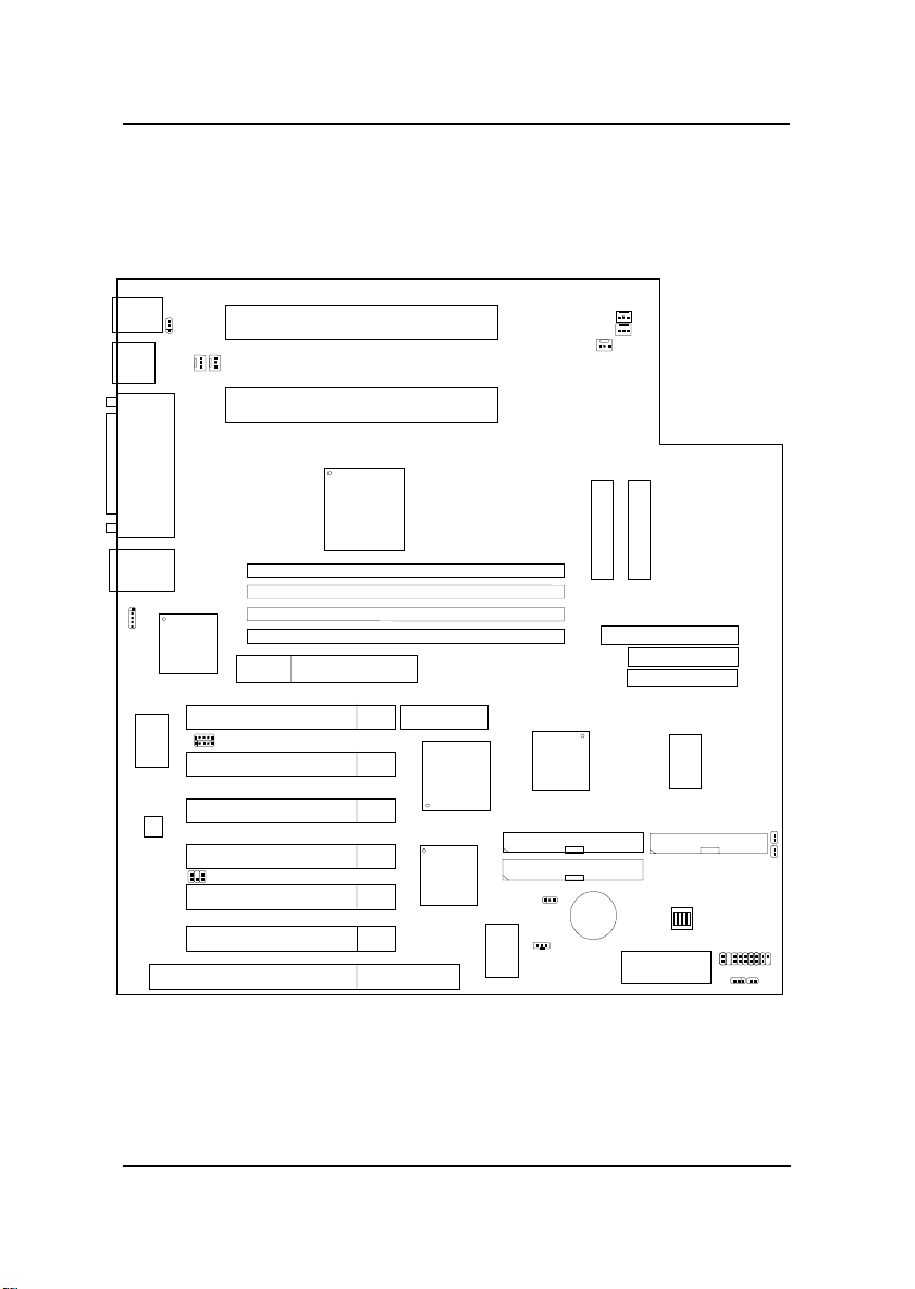
MSI MS-6135 User manual

CHAPTER 1 INTRODUCTION
1-1
Chapter 1
INTRODUCTION
The ATX GX1 Dual-P mainboard is a state-of-the-art dual-processor server
mainboard based on Intel®Pentium®II XeonTM processor. The Intel®
Pentium®II XeonTM processor is designed exclusively for powerful servers
and workstations.
The mainboard uses the highly integrated Intel®82440GX chipset to support
the PCI/ISA and Green standards, and to provide the Host/AGP bridge. The
82371EB chipset integrates all system control functions such as ACPI
(Advanced Configuration and Power Interface). The ACPI provides more
Energy Saving Features for the OSPM(OS Direct Power Management)
function. The Intel®82371EB chipset also improves the IDE transfer rate by
supporting Ultra DMA/33 IDE that transfers data at the rate of 33MB/s.
The mainboard also supports the System Hardware Monitor Controller as an
optional function. This function includes: CPU /power supply/chassis fan
revolution detect, CPU/system voltage monitor, system temperature monitor,
and chassis intrusion detect.

CHAPTER 1 INTRODUCTION
1-2
1.1 Mainboard Features
CPU
lDual Slot 2 for Intel®Pentium®II Xeon processor.
lSupport400MHzorfasterwith512KB,1MBor2MBintegratedL2cache.
Chipset
lIntel®82440GXAGPset.
lIntel®82371EBchipset.
OnboardSCSIConnector
lAdaptecAIC-7890/AIC3860
- support high performance 80Mbytes/sec Ultra 2 SCSI peripherals at a
cable length up to 12 meters.
PCI-To-PCIBridge
lDigital21152
- compliesfullywithRevision2.1ofPCILocalBusSpecification.
- support six PCI master.
MainMemory
lSupport eight memory banks using four 168-pin gold-lead DIMM sockets.
lSupportamaximum memorysizeof 2GB.
lSupport unbuffered or registered ECC(1-bit Error Code Correct) SDRAM.
lSupport 3.3v SDRAM DIMM.
Slots
lOne AGP (Accelerated Graphics Port) slot
- data transfer rates at 133MHz (with AC timing)
lSix 32-bit Master PCI Bus slots and one ISA bus slot (wherein 1 PCI/ISA
is shared).
lSupport 3.3v/5v PCI bus Interface.

CHAPTER 1 INTRODUCTION
1-3
On-BoardIDE
lAnIDEcontrollerontheIntel®82371EB ChipsetprovidesIDEHDD/CD-
ROM with PIO, Bus Master and Ultra DMA/33 operation modes.
lCan connect up to four IDE devices.
IntegratedSuperI/OController
lWinbond W83977F-AW I/O controller
- 1 floppy port supports 2 FDD with 360K, 720K, 1.2M, 1.44M and
2.88Mbytes.
-2serialport(COMA+COMB)
- 1 parallel port supports SPP/EPP/ECP mode
- 1 IrDA connector for SIR.
Network
lIntel®82558 10/100MB Ethernet
-ACPI
- Magic packet filtering to support wake-up on LAN.
-ARP &FLEXIBLEframefiltering.
- Software drivers are backwards compatible.
-1LanConnector(RJ-45)
USB
lTwo USB ports
BIOS
lThe mainboard BIOS provides “Plug & Play” BIOS which detects the
peripheral devices and expansion cards of the board automatically.
lIDE drive auto configure, Advanced Power Management (APM) 1.2,
ACPI 1.0, DMI 2.0, ECC/Parity support, LS120 support, Auto enable
onboardSCSIterminator.
Dimension
lCustomATXFormFactor : 33cm(L) x30.5cm(W)x 6 layersPCB

CHAPTER 1 INTRODUCTION
1-4
Mounting
l12 mounting holes.
SystemHardwareMonitor
lCPU/Power Supply/Chassis Fan Revolution Detect
lCPU Fan Control (the fan will automatically stop when the system enters
suspend mode)
lSystem Voltage Detect
lCPU Overheat Warning.
lDisplay Actual Current Voltage

CHAPTER 1 INTRODUCTION
1-5
1.2 Mainboard Layout
DIMM 1
Top: mouse
Bottom:
keyboard
Top:Port1
USB
Top: LPT
Bottom:
COMA
COMB
ISA SLOT 1
PCI SLOT 4
PCI SLOT 3
PCI SLOT 2
PCI SLOT 1
SLOT 2
FDC
BATT
+
IDE1
977TF-AW
ATX
Power Supply
BIOS
PIIX4E
JFP1
SW
CPUFA4
82558
PSFAN1
FW82443BX
AGP
Bottom:
Port2
CPUFA1
PCI SLOT 5
UltraSCSI
J1
JBAT1
JSOUND1
JWOL1
3860
System
Hardware
Monitor
JRMS1
HI-LAN
UltraWideSCSI
Adaptec
7890
PCI SLOT 6
DIMM 2
DIMM 3
DIMM 4
RJ-45 LAN
Connector
SLOT 2
JKBMB1
CPUFA3
CPUFA2
JMODEM
IDE2
Ultra2SCSI
ACTLAN
I/O
APIC
Digital
21152
Raid
Controller
ATX
Power Supply
MS-6135 ATX GX1 Dual-P Mainboard
IR1

CHAPTER 2 HARDWARE INSTALLATION
2-1
Chapter 2
HARDWARE INSTALLATION
2.1 Central Processing Unit: CPU
The mainboard operates with Intel®Pentium®II XeonTM processor.The
mainboard uses a CPU Slot called Slot 2 for easy CPU installation and a DIP
switch (SW1) to set the proper speed for the CPU. The CPU should always
have a Heat Sink attached to prevent overheating.

CHAPTER 2 HARDWARE INSTALLATION
2-2
2.1-1 CPU Installation Procedures
Retention Mechanism
Plastic Guide that holds
andsecure theprocessor
into the Slot 2 connector
Retention Cap
Plastic Guide that secure
the processor to the
RetentionMechanism.
1. Securethe mainboard
into the chassis. Then,
connectthe Retention
Mechanism into the
mainboard. Securewith
screws.
Intel®Pentium®II XeonTM processor Installation Proce-
dures

CHAPTER 2 HARDWARE INSTALLATION
2-3
5. Secure with screws.
2. Connectthe Retention
Capintotheprocessor.
Processor will only fit in
onedirection.
3. TheRetention Capgot two
mountingholes, which
should match with the
RetentionMechanism.
4. Inserttheprocessorinto
the Slot 2.

CHAPTER 2 HARDWARE INSTALLATION
2-4
6. Repeat steps 2 to 5 for
thesecond processor.
7. Theinstallationisnow
complete.
Note: To install a single Intel Pentium II XeonTM processor, refer to
Chapter 2 section 2.1-4.

CHAPTER 2 HARDWARE INSTALLATION
2-5
2.1-2 CPU Core Speed Derivation Procedure
The DIP Switch SW1 (1, 2, 3, and 4) is used to set the Core/Bus (Fraction)
ratio of the CPU. The actual core speed of the CPU is the Host Clock
Frequency multiplied by the Core/Bus ratio. For example:
If CPUClock = 100MHz
Core/Bus ratio = 4.5
then CPU core speed = Host Clock x Core/Busratio
= 100MHzx4.5
= 450MHz
1 2 3 4 Core/Bus Ratio
OFF ON ON ON 4
OFF ON OFF ON 4.5
OFF OFF ON ON 5
OFF OFF OFF ON 5.5
ON ON ON OFF 6
SW1 CPU

CHAPTER 2 HARDWARE INSTALLATION
2-6
2.1-3 CPU Speed Setting: SW1
To adjust the speed of the CPU, you must know the specifications of your
CPU (always ask the vendor for CPU spec.). Then look at Table 2.1 (400 ~
600MHzIntel®Pentium®IIXeonTM processor)for setting.
SW1
ON
1 2 3 4
Table 2.1 400 ~ 600MHz Intel®Pentium®II XeonTM processor
450MHz
500MHz
550MHz
600MHz
400MHz
CPUSPEED
(FSB 100MHz) CORE/BUSRATIO
SW1
ON
1 2 3 4
ON
1 2 3 4
ON
1 2 3 4
ON
1 2 3 4
ON
1 2 3 4

CHAPTER 2 HARDWARE INSTALLATION
2-7
2.1-4 CPU Terminator
The CPU terminator is used, when only one CPU is installed. You must
always install the CPU terminator on the empty CPU 2 slot.
CPU Terminator
Important:
To use dual CPU, it is strongly adviced that same CPU speed and
CPU stepping is used: which means that if you install 400MHz in the
1st CPU slot, then you must also install 400MHz on the 2nd slot.

CHAPTER 2 HARDWARE INSTALLATION
2-8
2.1-5 Fan Power Connectors: CPUFA1/CPUFA2/CPUFA3/
CPUFA4/PSFAN1
These connectors support system cooling fan with +12V. It supports three
pin head connector. When connecting the wire to the connector, always
take note that the red wire is the positive and should be connected to the
+12V, the black wire is Ground and should be connected to GND. If your
mainboard has System Hardware Monitor chipset on-board, you must use a
specially designed fan with speed sensor to take advantage of the CPU fan
speed monitor feature.
CPUFA1/2 : Processor#1 Fan Connector
CPUFA3/4 : Processor#2 Fan Connector
PSFAN1 : Power Supply Fan Connector
CPUFA3
GND
+12V
SENSOR
GND
+12V
NC
SENSOR +12V GND
CPUFA4 NC +12V GND
SENSOR +12V GND
PSFAN1
CPUFA2
CPUFA1

CHAPTER 2 HARDWARE INSTALLATION
2-9
2.2 Clear CMOS Jumper: JBAT1
A battery must be used to retain the mainboard configuration in CMOS
RAM. You must short 1-2 pins of JBAT1 to keep the CMOS data.
Keep Data
Clear CMOS
1
13
3
JBAT1
Note: You can clear CMOS by shorting 2-3 pin, while the system is off.
Then, return to 1-2 pin position. To be able to clear the CMOS, you
need to unplug the power plug of the system, because there’s a 3V
standby power which is provided by the power supply. Otherwise,
the CMOS will not be cleared.
Function
JBAT1
3
1

CHAPTER 2 HARDWARE INSTALLATION
2-10
2.3 Memory Installation
2.3-1 Memory Bank Configuration
The mainboard supports a maximum of 2 GB memory for registered DIMM
and 512MB for unbuffered DIMM: It provides four 168-pin DIMMs
(Double In-Line Memory Module) sockets. It supports 8 MB to 256 Mbytes
DIMMmemorymodule.
DIMM1(Bank0+ Bank1)
DIMM3(Bank4+ Bank5)
DIMM4(Bank6+ Bank7)
DIMM2(Bank2+ Bank3)

CHAPTER 2 HARDWARE INSTALLATION
2-11
A. HowtoinstallaDIMMModule
1. The DIMM slot has a two Notch Key “VOLT and DRAM”, so the
DIMM memory module can only fit in one direction.
2. Insert the DIMM memory module vertically into the DIMM slot.
Then push it in.
3. The plastic clip at the side of the DIMM slot will automatically
close.
Single Sided DIMM
Double Sided DIMM
VOLTDRAM
2.3-2 Memory Installation Procedures

CHAPTER 2 HARDWARE INSTALLATION
2-12
1. Supports SDRAM.
2. Supports registered/unbufferedDIMM.
3. To operate properly, at least one 168-pin DIMM module must be in-
stalled.
4. This mainboard supports Table Free memory, so memory can be installed
on DIMM1, DIMM2, DIMM 3, or DIMM 4 in any order.
5. Supports only 3.3 volt DIMM.
6. The DRAM addressing and the size supported by the mainboard is
shown below:
2.3-3 Memory Population Rules
Table 2.3-1 SDRAM Memory Addressing
16M 1Mx16 ASYM 12 8 8MBx4 16MBx8
2Mx8 ASYM 12 9 16MBx8 32MBx16
2Mx8 ASYM 13 8 16MBx8 32MBx16
4Mx4 ASYM 12 10 32MBx16 64MBx32
4Mx4 ASYM 14 8 32MBx16 64MBx32
64M 2Mx32 ASYM 12 9 16MBx2 32MBx4
2 bank 2Mx32 ASYM 13 8 16MBx2 32MBx4
4Mx16 ASYM 12 10 32MBx4 64MBx8
4Mx16 ASYM 14 8 32MBx4 64MBx8
8Mx8 ASYM 14 9 64MBx8 128MBx16
16Mx4 ASYM 14 10 128MBx16 256MBx32
64M 2Mx32 ASYM 13 8 16MBx2 32MBx4
4 bank 4Mx16 ASYM 14 8 32MBx4 64MBx8
8Mx8 ASYM 14 9 64MBx8 128MBx16
16Mx4 ASYM 14 10 128MBx16 256MBx32
DRAM
Tech.
DRAM
Density &
Width
DRAM
Addressing Address Size MB/DIMM
Row Column Single
Side(S) Double
Side(D)
no.
pcs. no.
pcs.

CHAPTER 2 HARDWARE INSTALLATION
2-13
2.4 Case Connector: JFP1
ThePowerSwitch,ResetSwitch,KeyLock,PowerLED, SpeakerandHDD
LED are all connected to the JFP1 connector block.
JFP1
Power
Switch
Power
LED
+
Reset
Switch
HDD
LED
9
1
10 14 15 18
+
Keylock
Speaker

CHAPTER 2 HARDWARE INSTALLATION
2-14
2.4-1 Power Switch
Connect to a 2-pin push button switch. This switch had the same feature
withJRMS1.
2.4-2 Reset Switch
Reset switch is used to reboot the system rather than turning the power ON/
OFF. Avoid rebooting while the HDD LED is lit. You can connect the Reset
switch from the system case to this pin.
2.4-3 Keylock
Keylock allows you to disable the keyboard for security purposes. You can
connect the keylock to this pin.
2.4-4 Power LED
The Power LED is always lit while the system power is on. You can connect
the Power LED from the system case to this pin.
GreenColor: Indicate the system is in full on mode.
OrangeColor: Indicate the system is in suspend mode.
2.4-5 Speaker
Speaker from the system case is connected to this pin.
If on-board speaker is available:
Shortpin14-15: On-board speaker Enabled.
Openpin14-15: On-board speaker Disabled.
2.4-6 HDD LED
HDD LED shows the activity of a hard disk drive. Avoid turning the power
off while the HDD led is lit. You can connect the HDD LED from the system
case to this pin.

CHAPTER 2 HARDWARE INSTALLATION
2-15
2.5 Floppy Disk Connector: FDC
The mainboard also provides a standard floppy disk connector FDC that
supports 360K, 720K, 1.2M, 1.44M and 2.88M floppy disk types. This
connector support the provided floppy drive ribbon cables.
FDC
1
Other manuals for MS-6135
1
This manual suits for next models
2
Table of contents
Other MSI Motherboard manuals

MSI
MSI MS-5191 User manual

MSI
MSI MAG X570S TORPEDO MAX User manual

MSI
MSI MS-6395 User manual

MSI
MSI B150A GAMING PRO User manual

MSI
MSI 865PE/G Neo2-P MS-6728 User manual

MSI
MSI PRO B550-P GEN3 User manual

MSI
MSI G45M2 Series User manual

MSI
MSI MS-98D6 User manual

MSI
MSI 945GCM5 Series User manual

MSI
MSI P45-8D Series User manual

MSI
MSI KT4A-V User manual

MSI
MSI MS7797 User manual

MSI
MSI K8T Neo2-F User manual

MSI
MSI MS-7520 ECLIPSE Series User manual

MSI
MSI MEG Z390 GODLIKE User manual

MSI
MSI PRO B660M-A CEC WIFI User manual

MSI
MSI PRO B660M-A WIFI DDR4 User manual

MSI
MSI MS-7140 User manual

MSI
MSI MS-6114 User manual

MSI
MSI MS-7314 User manual