MSI Z590-S01 User manual

1
Contents
Contents
2
3
8
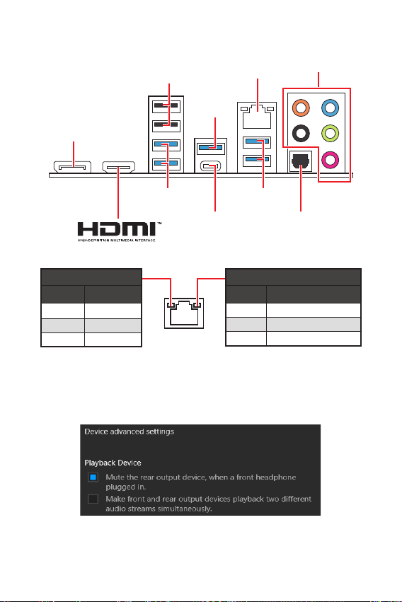
LAN Port LED Status Table........................................................................................8
9
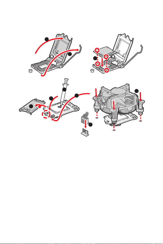
CPU Socket...............................................................................................................10
DIMM Slots................................................................................................................11
PCI_E1~5: PCIe Expansion Slots..............................................................................12
M2_1~2: M.2 Slots (Key M) .......................................................................................13
M2_3: M.2 Slot (Key E)..............................................................................................13
SATA1~4: SATA 6Gb/s Connectors...........................................................................14
JAUD1: Front Audio Connector ................................................................................14
JFP1, JFP2: Front Panel Connectors.......................................................................15
CPU_PWR1~2, ATX_PWR1: Power Connectors.......................................................16
JUSB1~2: USB 2.0 Connectors.................................................................................17
JUSB3~4: USB 3.2 Gen 1 5Gbps Connectors ...........................................................17
CPU_FAN1, PUMP_FAN1, SYS_FAN1~4: Fan Connectors......................................18
JTPM1: TPM Module Connector...............................................................................18
JCI1: Chassis Intrusion Connector...........................................................................19
JTBT1: Thunderbolt Add-on Card Connector ..........................................................19
JBAT1: Clear CMOS (Reset BIOS) Jumper...............................................................20
JRAINBOW1: Addressable RGB LED connectors (optional)....................................20
JRGB1: RGB LED connector ....................................................................................21
EZ Debug LED (optional) ..........................................................................................21
22
Installing Windows® 10.............................................................................................22
Installing Drivers......................................................................................................22
MSI Center................................................................................................................22
23
BIOS Setup................................................................................................................24
Entering BIOS Setup.................................................................................................24
BIOS User Guide.......................................................................................................24
Resetting BIOS..........................................................................................................25
Updating BIOS...........................................................................................................25
Thank you for purchasing the MSI®
motherboard. This User Guide gives information about
board layout, component overview, BIOS setup and software
installation.

2
The components included in this package are prone to damage from electrostatic
discharge (ESD). Please adhere to the following instructions to ensure successful
computer assembly.
Ensure that all components are securely connected. Loose connections may cause
the computer to not recognize a component or fail to start.
Hold the motherboard by the edges to avoid touching sensitive components.
It is recommended to wear an electrostatic discharge (ESD) wrist strap when
handling the motherboard to prevent electrostatic damage. If an ESD wrist strap is
not available, discharge yourself of static electricity by touching another metal object
before handling the motherboard.
Store the motherboard in an electrostatic shielding container or on an anti-static
pad whenever the motherboard is not installed.
Before turning on the computer, ensure that there are no loose screws or metal
components on the motherboard or anywhere within the computer case.
Do not boot the computer before installation is completed. This could cause
permanent damage to the components as well as injury to the user.
If you need help during any installation step, please consult a certified computer
technician.
Always turn off the power supply and unplug the power cord from the power outlet
before installing or removing any computer component.
Keep this user guide for future reference.
Keep this motherboard away from humidity.
Make sure that your electrical outlet provides the same voltage as is indicated on
the PSU, before connecting the PSU to the electrical outlet.
Place the power cord such a way that people can not step on it. Do not place
anything over the power cord.
All cautions and warnings on the motherboard should be noted.
If any of the following situations arises, get the motherboard checked by service
personnel:
Liquid has penetrated into the computer.
The motherboard has been exposed to moisture.
The motherboard does not work well or you can not get it work according to
user guide.
The motherboard has been dropped and damaged.
The motherboard has obvious sign of breakage.
Do not leave this motherboard in an environment above 60°C (140°F), it may
damage the motherboard.

3
Supports 10th Gen Intel® Core™ Processors, 11th Gen Intel®
Core™ Processors, Pentium® Gold and Celeron® Processors
Processor socket LGA1200
* Please go to intel.com for compatibility information.
Intel® Z590 chipset
4x DDR4 memory slots, support up to 128GB*
Supports 1R 2133/ 2666/ 2933 MHz for 10th Gen Intel® CPU
(by JEDEC & POR)
Supports 1R 2133/ 2666/ 2933/ 3200 MHz for 11th Gen Intel®
CPU (by JEDEC & POR)
Max overclocking frequency:
1DPC 1R Max speed up to 5333 MHz
1DPC 2R Max speed up to 4700+ MHz
2DPC 1R Max speed up to 4400+ MHz
2DPC 2R Max speed up to 4000+ MHz
Supports Dual-Channel mode
Supports non-ECC, un-buffered memory
Supports Intel® Extreme Memory Profile (XMP)
* Please refer to www.msi.com for more information on
compatible memory.
2x PCIe x16 slots
PCI_E1 slot (From CPU)
Support up to PCIe 4.0 for 11th Gen Intel® CPU
Support up to PCIe 3.0 for 10th Gen Intel® CPU
PCI_E3 slot (From Z590 chipset)
Supports up to PCIe 3.0 x4 speed
3x PCIe 3.0 x1 slots (From Z590 Chipset)
1x M.2 slot with E key for WiFi module only (M2_3)
Continued on next page

4
Continued from previous page
1x HDMI 1.4 with HDR port, supports a maximum 4096x2160
30Hz*/**
1x DisplayPort 1.4 port, supports a maximum resolution of
4K 60Hz*
* Available only on processors featuring integrated graphics.
** Graphics specifications may vary depending on the CPU
installed.
Realtek® ALC897 Codec
7.1-Channel High Definition Audio
Supports S/PDIF output
1x Intel® KTI225V 2.5Gbps LAN controller
4x SATA 6Gb/s ports (From Z590 Chipset)
2x M.2 slots (Key M)
M2_1 slot (From Processor)
Available only on 11th Gen Intel® CPU
Supports up to PCIe 4.0 x4
Supports 2242/ 2260/ 2280/ 22110 storage devices
M2_2 slot (From Z590 Chipset)
Supports up to PCIe 3.0 x4
Supports SATA up to 6Gb/s
Supports 2242/ 2260/ 2280 storage devices
Supports RAID 0, RAID 1 and RAID 10 for SATA storage
devices
Continued on next page

5
Continued from previous page
Intel® Z590 Chipset
1x USB3.2 Gen 2x2 20Gbps port (Type-C port on the
back panel)
7x USB 3.2 Gen 1 5Gbps ports (3 Type-A ports on the
back panel, 4 Type-A ports available through the internal
connector)
2x USB 2.0 ports on the back panel
Hub-ASM1074
2x USB 3.2 Gen 1 5Gbps ports on the back panel
Hub-GL850G
4x USB 2.0 ports available through the internal
connectors
1x 24-pin ATX main power connector
1x 8-pin ATX 12V power connector
1x 4-pin ATX 12V power connector
4x SATA 6Gb/s connectors
2x M.2 slots (M-Key)
1x M.2 slot (E-Key)
2x USB 3.2 Gen 1 5Gbps connectors (supports additional 4
USB 3.2 Gen 1 5Gbps ports)
2x USB 2.0 connectors (supports additional 4 USB 2.0 ports)
1x 4-pin CPU fan connector
1x 4-pin water-pump fan connector
4x 4-pin system fan connectors
1x Front panel audio connector
2x System panel connectors
1x Chassis Intrusion connector
1x Clear CMOS jumper
1x TPM module connector
1x TBT connector
Continued on next page

6
Continued from previous page
2x USB 2.0 Type-A ports
1x DisplayPort
1x HDMI port
5x USB 3.2 Gen 1 5Gbps Type-A ports
1x USB 3.2 Gen 2x2 20Gbps Type-C port
1x 2.5G LAN (RJ45) port
5x audio jacks
1x Optical S/PDIF OUT connector
1x 4-pin RGB LED connector
1x 3-pin RAINBOW LED connector (for Z590 PLUS only)
4x EZ Debug LED (for Z590 PLUS only)
NUVOTON NCT6687 Controller Chip
CPU/System/ Chipset temperature detection
CPU/System/ Pump fan speed detection
CPU/System/ Pump fan speed control
ATX Form Factor
12 x 9.6 in. (30.5 cm x 24.4 cm)
1x 256 Mb flash
UEFI AMI BIOS
ACPI 6.2, SMBIOS 3.0
Multi-language
Drivers
MSI Center
Intel Extreme Tuning Utility
CPU-Z MSI GAMING
Google Chrome™, Google Toolbar, Google Drive
Norton™ Internet Security Solution
Continued on next page

7
Continued from previous page
LAN Manager
Mystic Light
Frozr AI Cooling
User Scenario
True Color
Live Update
Hardware Monitor
Super Charger
Speed Up
Cooling
Smart Fan Control
Frozr AI Cooling
LED
Mystic Light Extension (RAINBOW) (for Z590 PLUS only)
Mystic Light Extension (RGB)
EZ DEBUG LED (for Z590 PLUS only)
Performance
DDR4 Boost
Core Boost
USB 3.2 Gen 2x2 20G
Protection
PCI-E Steel Armor
Experience
Click BIOS 5

8
Status
Off No link
Yellow Linked
Blinking Data activity
Status
Off 10 Mbps connection
Green 100/1000 Mbps connection
Orange 2.5 Gbps connection
To configure 7.1-channel audio, you have to connect front audio I/O module to JAUD1
connector and follow the below steps.
Click on the to open the dialog
below.
Select .
Plug your speakers to audio jacks on rear and front I/O panel. When you plug into
a device at an audio jack, a dialogue window will pop up asking you which device
is current connected.
2.5Gbps
LAN
USB 2.0 Type-A
USB 3.2 Gen
1 (5Gbps)
Type-A
USB 3.2 Gen
1 (5Gbps)
Type-A
USB 3.2 Gen
2x2 (20Gbps)
Type-C
USB 3.2 Gen
1 (5Gbps)
Type-A
DisplayPort
Audio Ports
Optical
S/PDIF-Out

9
* Distance from the center of the CPU to the nearest DIMM slot.
BAT1
50.77mm*
JTBT1
JRGB1
M2_2
M2_1
M2_3
JTPM1
SYS_FAN2
SYS_FAN1
SYS_FAN3
SYS_FAN4 JUSB2
JUSB1
CPU_FAN1
PUMP_FAN1
PCI_E1
PCI_E2
PCI_E3
PCI_E4
PCI_E5
Processor Socket
CPU_PWR1
JAUD1
JFP1
JRAINBOW1(optional)
JFP2
ATX_PWR1
DIMMB1
DIMMB2
DIMMA1
DIMMA2
CPU_PWR2
JUSB3
JUSB4
JCI1
JBAT1

10
Please install the CPU into the CPU socket as shown below.
Always unplug the power cord from the power outlet before installing or removing
the CPU.
Please retain the CPU protective cap after installing the processor. MSI will deal
with Return Merchandise Authorization (RMA) requests if only the motherboard
comes with the protective cap on the CPU socket.
When installing a CPU, always remember to install a CPU heatsink. A CPU heatsink
is necessary to prevent overheating and maintain system stability.
your system.
Overheating can seriously damage the CPU and motherboard. Always make sure
the cooling fans work properly to protect the CPU from overheating. Be sure to apply
an even layer of thermal paste (or thermal tape) between the CPU and the heatsink to
enhance heat dissipation.
Whenever the CPU is not installed, always protect the CPU socket pins by covering
the socket with the plastic cap.
If you purchased a separate CPU and heatsink/ cooler, Please refer to the docu-
mentation in the heatsink/ cooler package for more details about installation.
1
4
6
5
78
9
3
2

11
Please install the memory module into the DIMM slot as shown below.
1
2
3
2
13
DIMMB2
DIMMA2 DIMMA2
DIMMB2
DIMMB1
DIMMA2
DIMMA1

12
unplug the power supply power cable from the power outlet. Read the expansion
card’s documentation to check for any necessary additional hardware or software
changes.
If you install a large and heavy graphics card, you need to use a tool such as
to support its weight to prevent deformation
of the slot.
BAT1
: PCIe 4.0 x16 slot (CPU)
: PCIe 3.0 x1 slot (PCH)
Always insert memory modules in the
To ensure system stability for Dual channel mode, memory modules must be of the
same type, number and density.
Some memory modules may operate at a lower frequency than the marked value
when overclocking due to the memory frequency operates dependent on its Serial
frequency if you want to operate the memory at the marked or at a higher frequency.
installation or overclocking.
The stability and compatibility of installed memory module depend on installed
CPU and devices when overclocking.
Please refer to www.msi.com for more information on compatible memory.
: PCIe 3.0 x16 slot, supporting X4
speed) (PCH)
: PCIe 3.0 x1 slot (PCH)

13
Please install the M.2 device into the M.2_1 & M.2_2 slots as shown below.
1
3
Standoff
Supplied
M.2 screw 30º30º
2
Please install the Wi-Fi module into the M.2_3 slot as shown below.
1
Supplied
M.2 screw
30º
30º
2

14
These connectors are SATA 6Gb/s interface ports. Each connector can connect to one
SATA device.
SATA3
SATA1
SATA4
SATA2
Please do not fold the SATA cable at a 90-degree angle. Data loss may result
during transmission otherwise.
SATA cables have identical plugs on either sides of the cable. However, it is
saving purposes.
This connector allows you to connect audio jacks on the front panel.
1
2 10
9
1 MIC L 2 Ground
3 MIC R 4 NC
5 Head Phone R 6 MIC Detection
7 SENSE SEND 8 No Pin
9 Head Phone L 10 Head Phone Detection

15
These connectors connect to the switches and LEDs on the front panel.
1
2 10
9
+
+
+- --
-
+
Power LED
HDD LED Reset Switch
Reserved
Power Switch 1 HDD LED + 2 Power LED +
3 HDD LED - 4 Power LED -
5 Reset Switch 6 Power Switch
7 Reset Switch 8 Power Switch
9 Reserved 10 No Pin
JFP2 1
+
+-
-
Speaker
Buzzer 1 Speaker - 2 Buzzer +
3 Buzzer - 4 Speaker +
HDD LED
RESET SW
HDD LED HDD LED -
HDD LED +
POWER LED -
POWER LED +
POWER LED
JFP1

16
These connectors allow you to connect an ATX power supply.
Make sure that all the power cables are securely connected to a proper ATX power
supply to ensure stable operation of the motherboard.
24
131
12
ATX_PWR1
1 +3.3V 13 +3.3V
2 +3.3V 14 -12V
3 Ground 15 Ground
4 +5V 16 PS-ON#
5 Ground 17 Ground
6 +5V 18 Ground
7 Ground 19 Ground
8 PWR OK 20 Res
9 5VSB 21 +5V
10 +12V 22 +5V
11 +12V 23 +5V
12 +3.3V 24 Ground
5
41
8
CPU_PWR1
1 Ground 5 +12V
2 Ground 6 +12V
3 Ground 7 +12V
4 Ground 8 +12V
3
2 1
4CPU_PWR2
1 Ground 3 +12V
2 Ground 4 +12V

17
These connectors allow you to connect USB 3.2 Gen 1 5Gbps ports on the front panel.
1
10 11
20
1 Power 11 USB2.0+
2 USB3_RX_DN 12 USB2.0-
3 USB3_RX_DP 13 Ground
4 Ground 14 USB3_TX_C_DP
5 USB3_TX_C_DN 15 USB3_TX_C_DN
6 USB3_TX_C_DP 16 Ground
7 Ground 17 USB3_RX_DP
8 USB2.0- 18 USB3_RX_DN
9 USB2.0+ 19 Power
10 Ground 20 No Pin
Note that the Power and Ground pins must be connected correctly to avoid possible
damage.
This connectors allow you to connect USB 2.0 ports on the front panel.
Note that the VCC and Ground pins must be connected correctly to avoid possible
damage.
In order to recharge your iPad, iPhone and iPod through USB ports, please install
MSI® Center utility.
1
2 10
9
1 VCC 2 VCC
3 USB0- 4 USB1-
5 USB0+ 6 USB1+
7 Ground 8 Ground
9 No Pin 10 NC

18
You can adjust fan speed in
PWM Mode fan connectors provide constant 12V output and adjust fan speed with
speed control signal. When you plug a 3-pin (Non-PWM) fan to a fan connector in
PWM mode, the fan speed will always maintain at 100%, which might create a lot of
noise.
1
1 Ground 2 +12V
3 Sense 4 Speed Control Signal
CPU_FAN1 PWM mode 2A 24W
PUMP_FAN1 PWM mode 3A 36W
SYS_FAN1~4 PWM mode 1A 12W
1
2 12
11
1 SPI Power 2 SPI Chip Select
3
Master In Slave Out (SPI
Data)
4
Master Out Slave In (SPI
Data)
5 Reserved 6 SPI Clock
7 Ground 8 SPI Reset
9 Reserved 10 No Pin
11 Reserved 12 Interrupt Request
This connector is for TPM (Trusted Platform Module). Please refer to the TPM
security platform manual for more details and usages.

19
1
2 16
15
1 TBT_FORCE_PWR 2 TBT_S0IX_ENTRY_REQ
3TBT_CIO_PLUG_
EVENT# 4 TBT_S0IX_ENTRY_ACK
5 SLP_S3#_TBT 6 TBT_PSON_
OVERRIDE_N
7 SLP_S5#_TBT 8 No Pin
9 Ground 10 SMBCLK_VSB
11 DG_PEWAKE# 12 SMBDATA_VSB
13 TBT_RTD3_PWR_EN 14 Ground
15 TBT_CARD_DET_R# 16 PD_IRQ#
This connector allows you to connect the chassis intrusion switch cable.
Normal
(default) Trigger the chassis
intrusion event
Connect the connector to the chassis intrusion switch/ sensor on the
chassis.
Close the chassis cover.
Go to .
Set to .
Press F10 to save and exit and then press the key to select .
Once the chassis cover is opened again, a warning message will be displayed on
screen when the computer is turned on.
Go to .
Set to Reset.
Press to save and exit and then press the key to select .
This connector allows you to connect the add-on Thunderbolt I/O card.

20
There is CMOS memory onboard that is external powered from a battery located on
the motherboard to save system configuration data. If you want to clear the system
configuration, set the jumpers to clear the CMOS memory.
Keep Data
(default) Clear CMOS/ Reset
BIOS
Power off the computer and unplug the power cord.
Use a jumper cap to short for about 5-10 seconds.
Remove the jumper cap from .
Plug the power cord and power on the computer.
The JRAINBOW connector allows you to connect the WS2812B Individually
Addressable RGB LED strips 5V.
Do not connect the wrong type of LED strips. The JRGB connector and the JRAINBOW
connector provide different voltages, and connecting the 5V LED strip to the JRGB
connector will result in damage to the LED strip.
The JRAINBOW connector supports up to 75 LEDs WS2812B Individually Address-
able RGB LED strips (5V/Data/Ground) with the maximum power rating of 3A (5V). In
the case of 20% brightness, the connector supports up to 200 LEDs.
before installing or removing the RGB LED strip.
Please use MSI’s software to control the extended LED strip.
11 +5V 2 Data
3 No Pin 4 Ground
This manual suits for next models
1
Table of contents
Languages:
Other MSI Motherboard manuals

MSI
MSI MEG Z690 ACE User manual

MSI
MSI 990FXA User manual

MSI
MSI Z170A GAMING PRO CARBON User manual

MSI
MSI MS-6545 User manual

MSI
MSI Z87 MPOWER MAX User manual

MSI
MSI 945 Neo5 Series User manual

MSI
MSI B450-A PRO User manual

MSI
MSI A320M PRO-VH PLUS User manual

MSI
MSI PRO B550-VC User manual

MSI
MSI KT4 Ultra User manual

MSI
MSI MS-6566E User manual

MSI
MSI 845EV User manual

MSI
MSI PRO B660M-G DDR4 User manual

MSI
MSI 915G Neo2-FR User manual

MSI
MSI H170 GAMING M3 User manual

MSI
MSI MPG X299M GAMING EDGE AC User manual

MSI
MSI H55-GD65 Series User manual

MSI
MSI MS-7036 User manual

MSI
MSI MS-6378 Instruction manual

MSI
MSI B350M MORTAR ARCTIC User manual