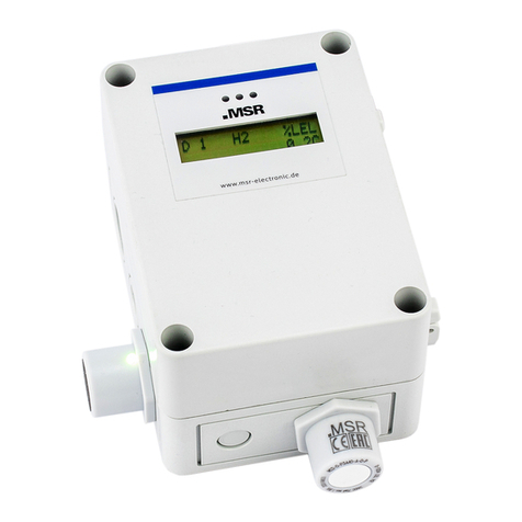
MSR ELECTRONIC PolyXeta 2 Series User manual

PolyXetais a registered trademark of MSR Made in Germany GAPX2_Freon_E_2020_05_18
Phone: +49 8531 9004-0 Fax: +49 8531 9004-54 Specification subject to change without notice
MSR-Electronic GmbH, Buergermeister-Schoenbauer-Str. 13, D 94060 Pocking www.msr-electronic.de
Gas Detector Series PolyXeta2 with Semi-conductor Sensor
for Freon Gases and Refrigerants for Zone1 and Zone 2
User Manual
Edition: English, 2020_05_18 V_1.4
PX2 YouTube Video
Up-to-date data sheets and user manuals can be found in the download area on www.msr-24.com.

User Manual - PolyXeta®2 Detector with HL Sensor
for Refrigerant Gases - May_2020
Page 2
PolyXetais a registered trademark of MSR Made in Germany GAPX2_Freon_E_2020_05_18
Phone: +49 8531 9004-0 Fax: +49 8531 9004-54 Specification subject to change without notice
MSR-Electronic GmbH, Buergermeister-Schoenbauer-Str. 13, D 94060 Pocking www.msr-electronic.de
1Notes and General Information .............................................................................4
1.1 Applicability ........................................................................................................................... 4
1.2 Intended Use .......................................................................................................................... 4
1.3 For Your Safety ....................................................................................................................... 4
1.4 Installer’s and Operator’s Responsibilities ............................................................................ 4
1.5 Maintenance ........................................................................................................................... 4
1.6 Liability................................................................................................................................... 4
1.7 Approvals................................................................................................................................ 5
1.7.1 Marking and Certificates according to ATEX Directive 2014/34/EU ................................. 5
1.7.2 Marking and Certificates according to IECEx only for PX2-1............................................. 5
1.7.3 Terms and Conditions for Safe Use .................................................................................... 5
1.7.4 Listing of Freon Gases......................................................................................................... 6
1.7.5 Listing of Ammonia............................................................................................................. 7
2General Description ...............................................................................................7
2.1 Device Description ................................................................................................................. 7
2.2 Measurement Principles......................................................................................................... 7
3Mounting Instructions............................................................................................8
3.1 Site of Installation .................................................................................................................. 8
3.2 Installation Work .................................................................................................................... 8
4Electrical Installation ...........................................................................................10
4.1 General Notes....................................................................................................................... 10
4.2 Connection Diagram............................................................................................................. 11
5Commissioning.....................................................................................................12
5.1 General Notes....................................................................................................................... 12
5.2 Check / Change of Operating Parameters............................................................................ 12
5.3 Running-in Characteristics ................................................................................................... 12
5.4 Functional Test ..................................................................................................................... 13
6Operating Modes..................................................................................................14
6.1 Restart (Diagnostic and Warm-up Stage)............................................................................. 14
6.2 Measuring Mode ................................................................................................................... 14
6.2.1 Alarm Acknowledgement ................................................................................................. 15
6.3 Special Mode ........................................................................................................................ 15
6.4 Faults .................................................................................................................................... 16
7Notes on Usage.....................................................................................................17
7.1 Ambient Conditions.............................................................................................................. 17
7.2 Further Notes and Restrictions............................................................................................. 17

User Manual - PolyXeta®2 Detector with HL Sensor
for Refrigerant Gases - May_2020
Page 3
PolyXetais a registered trademark of MSR Made in Germany GAPX2_Freon_E_2020_05_18
Phone: +49 8531 9004-0 Fax: +49 8531 9004-54 Specification subject to change without notice
MSR-Electronic GmbH, Buergermeister-Schoenbauer-Str. 13, D 94060 Pocking www.msr-electronic.de
8Maintenance and Service .....................................................................................18
8.1 Visual Inspection .................................................................................................................. 18
8.2 Functional Control / Calibration and Adjustment................................................................ 18
8.3 System Check / Proof Test.................................................................................................... 19
8.3.1 Necessary Equipment and Gases...................................................................................... 20
8.4 Calibration ............................................................................................................................ 20
8.4.1 Preliminaries..................................................................................................................... 20
8.4.2 Procedure for Calibration with Tool or Display................................................................ 21
8.4.3 Extended Calibration: ....................................................................................................... 21
8.5 Repairs.................................................................................................................................. 21
9Exchange of Sensor Head.....................................................................................22
9.1 General Notes....................................................................................................................... 22
9.2 Exchange of Sensor Head..................................................................................................... 22
9.3 Recommissioning ................................................................................................................. 22
9.4 Send Sensor Head Back for Calibration ............................................................................... 22
10 Sensor Specification of Semi-conductors for Freon Gases .................................23
11 Display..................................................................................................................25
11.1 Assembly, Disassembly ........................................................................................................ 25
11.2 Status LED............................................................................................................................. 26
11.3 Operation.............................................................................................................................. 26
11.4 Menu..................................................................................................................................... 26
11.5 Deadband ............................................................................................................................. 26
12 List of Spare Parts, Accessories ...........................................................................27
12.1 List of Spare Parts................................................................................................................. 27
12.2 Accessories ........................................................................................................................... 28
13 Specifications.......................................................................................................29
14 Type Examinations, Declarations of Conformity.................................................31
15 Decommissioning.................................................................................................37
16 Device Disposal....................................................................................................37
17 Definitions............................................................................................................37
18 History of Document Versions .............................................................................38

User Manual - PolyXeta®2 Detector with HL Sensor
for Refrigerant Gases - May_2020
Page 4
PolyXetais a registered trademark of MSR Made in Germany GAPX2_Freon_E_2020_05_18
Phone: +49 8531 9004-0 Fax: +49 8531 9004-54 Specification subject to change without notice
MSR-Electronic GmbH, Buergermeister-Schoenbauer-Str. 13, D 94060 Pocking www.msr-electronic.de
1Notes and General Information
1.1 Applicability
1. PolyXeta2 gas warning device with semi-conductor sensor for Freon gases and Ammonia,
series PX2-1…with Ex db protection, for zone 1 and 2
series PX2-2…with Ex nA protection, for zone 1 and 2
2. PolyXeta2 sensor head with semi-conductor sensor for Freon gases and Ammonia,
series SX1... with Ex db protection, for zone 1 and 2
1.2 Intended Use
The PolyXeta2 fixed gas detectors of the PX2-1 series are designed to detect and warn of Freon refrigerant
gases and Ammonia in the hazardous areas of zones 1 and 2 according to Directive 2014/34/EU.
The PolyXeta2 fixed gas detectors of the PX2-2 series are designed to detect and warn of Freon refrigerant
gases and Ammonia in the hazardous areas of zone 2 according to Directive 2014/34/EU.
The gas detectors are e.g. suitable for use in the chemical, petrochemical and offshore industry, etc. for
indoor and outdoor applications within the environmental conditions specified in the technical data.
1.3 For Your Safety
These operating instructions must be read and strictly followed by all persons installing, using, servicing and
inspecting the product. Furthermore, the operating instructions “Service Tool and Display for µGard2,
PolyGard2, PolyXeta2”must be read and obeyed if the PolyXeta2 has a display or if the Service Tool is
used. The product can only fulfil its intended functions if installed, used, serviced, maintained and controlled
according to the specifications of MSR-Electronic GmbH.
The factory settings of the measuring point, relay and system parameters and the device address are
documented in the configuration card supplied with each device on delivery.
1.4 Installer’s and Operator’s Responsibilities
It is the installer’s and operator’s responsibility to ensure that all PolyXeta®2 devices are installed and used
in compliance with all national and local regulations and requirements. The gas warning device must be
checked by an expert for correct installation and functioning before starting the measuring operation.
BGR 500 chapter 2.33 has to be applied in Germany.
The PolyXeta2 gas detector has been calibrated and tested for functionality at the factory before delivery.
When starting up, however, you have to perform and document a function testing using test gas.
1.5 Maintenance
Regular maintenance has to be performed according to the instructions in chapter 8.
1.6 Liability
MSR-Electronic GmbH will assume no liability if the device is not used properly or as intended. The installer
and operator are solely responsible for the interpretation and the use of the product.
If the product is not used, maintained or repaired according to the specifications in the user manual,
warranty and product liability claims as well as claims arising from any guarantees that MSR-Electronic GmbH
assumes for the product will lapse.

User Manual - PolyXeta®2 Detector with HL Sensor
for Refrigerant Gases - May_2020
Page 5
PolyXetais a registered trademark of MSR Made in Germany GAPX2_Freon_E_2020_05_18
Phone: +49 8531 9004-0 Fax: +49 8531 9004-54 Specification subject to change without notice
MSR-Electronic GmbH, Buergermeister-Schoenbauer-Str. 13, D 94060 Pocking www.msr-electronic.de
1.7 Approvals
The PolyXeta®2 gas warning device PX2-1 is approved for use in potentially explosive atmospheres of zone
1 and 2 by DEKRA Testing and Certification GmbH.
The PolyXeta®2 gas warning device PX2-2 is certified for use in zone 2 by the conformity declaration of the
manufacturer.
1.7.1 Marking and Certificates according to ATEX Directive 2014/34/EU
PX2-1 (Zone 1 und 2)
Sensorkopf SX1
PX2-2 (Zone 2)
Marking
II 2G Ex db IIC T4 Gb
0158
-25 °C < Ta < +60 °C
II 3G Ex nA IIC T4 Gb
-25 °C < Ta < +60 °C
EC Type Examination
Certificate
BVS 15 ATEX E 129 X
--
EG Konformitäts-
erklärung für Zone 2
--
CE_PX2_2_Zone2_1808
Protections
EN 60079-0: 2012 &
EN 60079-1: 2014 (Ex-db)
EN 60079-0: 2012 &
EN 60079-15: 2011 (Ex-nA)
1.7.2 Marking and Certificates according to IECEx only for PX2-1
Marking: Ex db IIC T4 Gb
-25 °C < Ta < +60 °C
IECEx Certificate Conformity: IECEx BVS 16.0038X
Protections: IEC 60079-0: 2011 & IEC 60079-1: 2014 (Ex-db)
1.7.3 Terms and Conditions for Safe Use
Temperature range -25 °C < Ta < +60 °C
Mounting position: wall mounting with the sensor head downwards

User Manual - PolyXeta®2 Detector with HL Sensor
for Refrigerant Gases - May_2020
Page 6
PolyXetais a registered trademark of MSR Made in Germany GAPX2_Freon_E_2020_05_18
Phone: +49 8531 9004-0 Fax: +49 8531 9004-54 Specification subject to change without notice
MSR-Electronic GmbH, Buergermeister-Schoenbauer-Str. 13, D 94060 Pocking www.msr-electronic.de
1.7.4 Listing of Freon Gases
MSR
Freon
group
MSR code
Freon
type
Calibration
gas
Group
Measuring
range
Relative
gas density
(air =1)
FR02
2061-01
R23
R23
HFC
2000 ppm
2.4
2061-02
R508b
R23
HFC
2000 ppm
> Air
FR03
2063-01
R1234yf
R1234yf
HFO
2000 ppm
> Air
2063-02
R452a
R1234yf
HFO
2000 ppm
> 1
2063-05
R455a
R1234yf
HFO
2000 ppm
> Air
2063-06
R454b
R1234yf
HFO
2000 ppm
> Air
2063-07
R1234ze
R1234yf
HFO
2000 ppm
> Air
FR04
2064-01
R123
R123
HCFC
2000 ppm
> Air
FR06
2070-01
R22
R22
HCFC
2000 ppm
3
2070-02
R401a
R22
HCFC
2000 ppm
> Air
2070-03
R401b
R22
HCFC
2000 ppm
> Air
2070-04
R402a
R22
HCFC
2000 ppm
> Air
2070-05
R402b
R22
HCFC
2000 ppm
> Air
2070-06
R403a
R22
HCFC
2000 ppm
> Air
2070-07
R408a
R22
HCFC
2000 ppm
> Air
2070-08
R409a
R22
HCFC
2000 ppm
> Air
2070-09
R411a
R22
HFC
2000 ppm
> Air
FR07
2077-01
R134a
R134a
HFC
2000 ppm
> Air
2077-02
R407a
R134a
HFC
2000 ppm
> Air
2077-03
R416a
R134a
HFC
2000 ppm
> Air
2077-04
R417a
R134a
HFC
2000 ppm
> Air
2077-05
R422a
R134a
HFC
2000 ppm
> Air
2077-06
R422d
R134a
HFC
2000 ppm
> Air
2077-07
R427a
R134a
HFC
2000 ppm
> Air
2077-08
R437a
R134a
HFC
2000 ppm
> Air
2077-09
R438a
R134a
HFC
2000 ppm
> Air
2077-10
R449a
R134a
HFC
2000 ppm
> Air
2077-11
R407f
R134a
HFC
2000 ppm
> Air
FR08
2080-01
R125
R407c
HFC
2000 ppm
4.2
2080-02
R32
R407c
CFC
2000 ppm
1.8
2080-03
R404a
R407c
HFC
2000 ppm
3.45
2080-04
R407c
R407c
HFC
2000 ppm
> 1
2080-05
R410a
R407c
HFC
2000 ppm
2.3
2080-06
R434a
R407c
HFC
2000 ppm
> Air
2080-07
R507a
R407c
HFC
2000 ppm
3.45
2080-08
R448a
R407c
HFC
2000 ppm
1.55
2080-09
R452b
R407c
HFO
2000 ppm
> Air
2080-10
R143b
R407c
HFO
2000 ppm
> Air
%LFL
2020-01
R32
R32
CFC
0–50 % LEL
1.8
2020-02
R455a
R455a
HFO
0–50 % LEL
> Air
2020-03
R454b
R454b
HFO
0–50 % LEL
> Air
2020-04
R1234yf
R1234yf
HFO
0–50 % LEL
> Air
2020-05
R1234ze
R1234ze
HFO
0–50 % LEL
> Air
Table 1.1: Available sensor heads for Freon gases

User Manual - PolyXeta®2 Detector with HL Sensor
for Refrigerant Gases - May_2020
Page 7
PolyXetais a registered trademark of MSR Made in Germany GAPX2_Freon_E_2020_05_18
Phone: +49 8531 9004-0 Fax: +49 8531 9004-54 Specification subject to change without notice
MSR-Electronic GmbH, Buergermeister-Schoenbauer-Str. 13, D 94060 Pocking www.msr-electronic.de
1.7.5 Listing of Ammonia
MSR code
Freon
type
Calibration
gas
Measuring
range
Relative gas
density
(air =1)
S2125-C
R717
NH3
1000 ppm
0,59
S2125-F
R717
NH3
10.000 ppm
0,59
Table 1.2: Available sensor heads for Ammonia
2General Description
2.1 Device Description
The fixed gas detector type "PX2" consists of a sensor head and an I/O unit.
The series PX2-1 is approved according to ATEX and IECEx certified for zone 1 and 2.
The series PX2-2 is certified by the manufacturer’s ATEX declaration conformity for zone 2.
The sensor head consisting of the gas sensor and the evaluation, calibration and diagnostic electronics
is an independent unit in flameproof stainless-steel housing (Ex d) with an external thread NPT ¾ ".
All sensor data are stored in the sensor head. After the end of the calibration period or at the end of
the sensor lifetime, the sensor can easily be replaced by a calibrated or a new sensor head.
The I/O unit including the operating power supply communicates with the sensor head via the internal
local bus, monitors the communication and translates the measured value of the sensor head into a 4-
20 mA signal. The value of the gas concentration and other relevant data and status messages are
available on the central bus. The alarm relay is activated when the alarm threshold is exceeded. In
case of a fault the fault relay and the analog output change into fault state and the fault message is
transmitted via the central bus. An optional display unit with indication of the measurement values
and status LEDs can be integrated behind a viewing window. The I/O unit is installed in a flameproof
(Ex db for PX2-1, Ex nA for PX2-2) die-cast housing with up to four openings with NPT ¾ " female
threads according to standard ANSI B1.20.1 for receiving sensor head and cable glands.
2.2 Measurement Principles
See chapter 10 “Sensor Specification”.

User Manual - PolyXeta®2 Detector with HL Sensor
for Refrigerant Gases - May_2020
Page 8
PolyXetais a registered trademark of MSR Made in Germany GAPX2_Freon_E_2020_05_18
Phone: +49 8531 9004-0 Fax: +49 8531 9004-54 Specification subject to change without notice
MSR-Electronic GmbH, Buergermeister-Schoenbauer-Str. 13, D 94060 Pocking www.msr-electronic.de
3Mounting Instructions
Check for completeness and accuracy using the delivery documents and the identification label
on the device.
3.1 Site of Installation
When choosing the mounting location, you have to consider the ambient conditions in order to get
representative measurement results. Please pay special attention to the following factors:
•External heat sources are not allowed on the installation site.
•Choose mounting location of the sensor according to the local regulations.
•Consider ventilation conditions! Do not mount the transmitter next to air passages or suction holes.
•The sample gas must pass the sensor even under adverse flow conditions. A flow test can be
performed for instance with smoke tubes.
•If the flow conditions are > 6 m/s, it is advisable to use a wind shield.
•Mount the transmitter at a location with minimum vibration and minimum variation in temperature
•In case of very difficult environmental conditions caused by dripping, splash, rain, condenser water
or dusts in the atmosphere, which are above the IP 65 dust and water protection, additional
accessories may be necessary to enable the use of the device. Please contact the manufacturer in
such cases.
•Provide adequate space around the sensor for maintenance and calibration work.
•The installation height depends on the relative gas density of the monitored gas type.
Freon
group
Gas
type
Relative density
(air = 1)
Recommended
mounting height
Calibraiton interval
FR02
R23
2.4
0.3 m above floor
12 months
FR03
R1234yf
4
0.3 m above floor
12 months
FR04
R123
> Luft
0.3 m above floor
12 months
FR06
R22
3
0.3 m above floor
12 months
FR07
R134a
>1
0.5 m above floor
12 months
FR08
R407c
2.3
0.3 m above floor
12 months
%LFL
R32
1.8
0.3 m above floor
12 months
R717 (NH3)
0.59
Ceiling
12 months
Table 3.1: Mounting heights
3.2 Installation Work
Assembly work must only be carried out under gas-free conditions.
The housing must neither be drilled nor be drilled through.
The installation position of the gas detector is always vertical, with the sensor head
downwards.
The mounting is done without opening the housing by using the two holes (D = 8 mm) of the fastening strap
with suitable screws. The exact dimensions are shown in the drawing "Dimensions and Mounting", fig. 3.1.

User Manual - PolyXeta®2 Detector with HL Sensor
for Refrigerant Gases - May_2020
Page 9
PolyXetais a registered trademark of MSR Made in Germany GAPX2_Freon_E_2020_05_18
Phone: +49 8531 9004-0 Fax: +49 8531 9004-54 Specification subject to change without notice
MSR-Electronic GmbH, Buergermeister-Schoenbauer-Str. 13, D 94060 Pocking www.msr-electronic.de
Depending on the housing version the inlets 2 and 4
are tightly closed or closed by blind plugs.
Fig.3.1: Dimensions and Mounting
NPT 3/4”(ANSI B1.20.1)
Internal Thread
NPT3/4”(ANSI B1.20.1)
Internal Thread
Blank Plug
Entry 4
Entry 1
Entry 2
Entry 3
NPT3/4”(ANSI B1.20.1)
Internal Thread
Cable Glands
60
95
X= depending ontype
of cable gland
60
42 X
30
60 65
Sensor
Head
M30x 1,5
External Thread
Blank Plug
NPT 3/4”(ANSI B1.20.1)
Internal Thread
D=8
D=8
81,5
81,5
Mounting Plate
65
8
83
40
60

User Manual - PolyXeta®2 Detector with HL Sensor
for Refrigerant Gases - May_2020
Page 10
PolyXetais a registered trademark of MSR Made in Germany GAPX2_Freon_E_2020_05_18
Phone: +49 8531 9004-0 Fax: +49 8531 9004-54 Specification subject to change without notice
MSR-Electronic GmbH, Buergermeister-Schoenbauer-Str. 13, D 94060 Pocking www.msr-electronic.de
4Electrical Installation
The instrument PX2-1 must only be opened under gas-free and voltage-free conditions.
The instrument PX2-2 should only be opened under gas-free and voltage-free
conditions.
The enclosed cable gland has to be checked for admissibility for the requested
requirements before installation in position “Entry 3”. If the instrument is supplied
without cable gland, a special cable gland approved for Ex protection class Ex db (PX2-1)
or nA (PX2-2) and for the requirements of the application has to be mounted there.
When inserting the cables, you have to strictly follow the instructions enclosed to the
cable glands.
No insulating sealing material must be poured into the NPT ¾ "threads of the cable
gland and blanking plugs because the potential equalization between housing and cable
gland / blind plugs is via the thread.
The cable gland / blind plugs must be tightened with a torque key with 15 Nm. Only
when doing so you can ensure the required tightness.
After completion of work, the instrument must be closed again. The cover has to be
completely screwed in and secured with the locking screw against inadvertent
loosening.
4.1 General Notes
•In the version with display, the terminals are located behind the display. The required disassembly
and subsequent assembly of the display is described in chapter 11.
•Only a professional should perform the wiring and the connection of the electrical installation
according to the wiring diagram in compliance with the relevant regulations and only when de-
energized!
•When connecting cables and conductors, please observe minimum length of 3 m according to EN
60079-14.
•Connect the housing to the equipotential bonding via the external ground terminal.
•Depending on the model there are female threads NPT ¾ inch on the housing at the positions "Entry
2 and 4" for placing additional cable glands. These inlets are factory sealed with original plugs. After
completing the installation work, make sure that all unused entries are closed with blind plugs
approved for Ex db (PX2-1) or nA (PX2-2) and for the requirements of the application. Thread adapters
for reducing the cable glands or dummy plugs are not admitted.
•All terminals are Ex e type with spring contact and push actuation. The permissible conductor cross
section is 0.2 to 2.5 mm2for single wires and multi-wire cables.
•Use cables with a braided shield with > 95 % coverage for compliance with the interference
immunity. The shield must be connected to the inside connection of the housing with a maximum
length of about 35 mm.
•For the recommended cross sections and lengths please refer to the table 4.1 "Cables".
•The analog output signal of warning devices without display can be used for the measurement
control. To carry out these regular checks with the housing closed it is recommended to lead the
analog signal out to the safe area via a cable.
•To comply with the requirements of servicing or operating the device without opening it, it is
possible to calibrate or operate the device remotely via the central bus. For this it is necessary to
lead the central bus out to the safe area via a cable.

User Manual - PolyXeta®2 Detector with HL Sensor
for Refrigerant Gases - May_2020
Page 11
PolyXetais a registered trademark of MSR Made in Germany GAPX2_Freon_E_2020_05_18
Phone: +49 8531 9004-0 Fax: +49 8531 9004-54 Specification subject to change without notice
MSR-Electronic GmbH, Buergermeister-Schoenbauer-Str. 13, D 94060 Pocking www.msr-electronic.de
The enclosed cable gland has a feed-through range of 9 to 16 mm.
The minimum diameter of the cable used must therefore be > 9 mm.
Cross-section
(mm2)
Max. length (m) for 24 V DC1
With
display
With relay
Relay & display
With sensor head for combustible gases (type PX2-X20…)
Operating voltage
with 4-20 mA signal
0.5
600
500
400
250
1.0
1000
800
700
500
Operating voltage
with central bus
0.5
900
500
400
300
1.0
900
900
800
700
Table 4.1: Cables
1 The max. cable lengths and our recommendation don’t consider any local conditions, like fire protection, national regulations
etc.
4.2 Connection Diagram
Alarm Relay = R1 Parameter set
Fault Relay = R2 Parameter set
Fig. 4.1: Connection diagram with terminal positions
GasAlarm Device PX2...
234567891011 1
+ 24 VDC
+ 24 VDC
GND
BUS_A
BUS_B
4 - 20 mA Output
Alarm Relay
(optional)
(closed in
measuring mode)
Fault Relay
(optional)
NPT 3/4”(ANSI B1.20.1)
Internal Thread
NPT 3/4”(ANSI B1.20.1)
Internal Thread
NPT 3/4”(ANSI B1.20.1)
Internal Thread
Blind Plug
Inlet 1
Inlet 2
Inlet 3
Sensor
Kopf
Cable Glands
Blind Plug
Inlet 4
NPT 3/4”(ANSI B1.20.1)
Internal Thread
Sensor
Head
Service
Tool
Status
LED
1
2
3
4
5
6
7
8
9
10
11
6
Sensor
Head
Push-Button

User Manual - PolyXeta®2 Detector with HL Sensor
for Refrigerant Gases - May_2020
Page 12
PolyXetais a registered trademark of MSR Made in Germany GAPX2_Freon_E_2020_05_18
Phone: +49 8531 9004-0 Fax: +49 8531 9004-54 Specification subject to change without notice
MSR-Electronic GmbH, Buergermeister-Schoenbauer-Str. 13, D 94060 Pocking www.msr-electronic.de
5Commissioning
5.1 General Notes
Before delivery all PX2 gas detectors without exception run through a complete functional test with an initial
calibration of the sensors as documented in the enclosed calibration protocol.
However, transportation, storage, installation or other environmental conditions may lead to (mostly small)
deviations. It is therefore necessary that a person authorized by the manufacturer or alternatively an expert
puts the device properly into operation and performs a functional test.
5.2 Check / Change of Operating Parameters
The complete parameter set is stored in the PX2 gas detector in a fail-safe way and documented in the
enclosed calibration and test record as well as in the PolyXeta®2 configuration card. Necessary changes of
parameters for adaptation to the application can be done by qualified persons only in the display and if not
available by means of the service tool.
The parameter functions as well as the menu navigation and operation are described in the User Manuals of
“Service Tool and Display” for PolyXeta®2.
Relevant standard
parameters
Freon measuring range 2000 ppm
Freon measuring range 50 % LEL
Meas. range
20–2000 ppm
0–50 % LEL
Alarm threshold 1
700 ppm
10 % LEL ↑
↑
↑
↑
Alarm threshold 2
1000 ppm
20 % LEL ↑
Hysteresis
50 ppm
2 % LEL
Alarm 1
Not latching
Not latching
Alarm 2
Latching
Latching
Alarm relay 1
Assigned to 1 and 2, energized,
(Alarm OFF = Relay ON)
Assigned to 1 and 2, energized,
(Alarm OFF = Relay ON)
Table 5.1: Relevant Standard Parameters
5.3 Running-in Characteristics
After switching on or after an internal reset of the microcontroller, the PX2 detector always runs through a
start routine with defined status of the outputs. The start always begins with the diagnosis and warm-up
stages. When they have succeeded and finished, the measurement operation starts. External intervention is
not possible during this start routine.

User Manual - PolyXeta®2 Detector with HL Sensor
for Refrigerant Gases - May_2020
Page 13
PolyXetais a registered trademark of MSR Made in Germany GAPX2_Freon_E_2020_05_18
Phone: +49 8531 9004-0 Fax: +49 8531 9004-54 Specification subject to change without notice
MSR-Electronic GmbH, Buergermeister-Schoenbauer-Str. 13, D 94060 Pocking www.msr-electronic.de
The states of analog output, relays, central bus and signal LEDs for all operating stages are shown in the
following table.
Start
Status LED
Analog
Output
Relays
Central Bus
Power
Alarm
Fault
Alarm
Fault
Diagnosis (~ 0,5 sec)
< 2 mA
OFF
Error4
Communication STOP
OK
Warm-up period
< 2 mA
OFF
Error4
Communication STOP
OK
Measuring mode
6
2
4-20 mA1
3
OK5
Communication OK
Maintenance mess.
2
4-20 mA1
3
OK5
Communication OK
Special mode
6
7
2 mA8
7
Error4
Communication OK
Detected fault
6
7
2 mA
7
Error 4
Communication OK
Processor failure
< 1 mA
OFF
Error 4
Communication STOP
Table 5.2: Status operating modes
1Depends on the measured gas concentration
2Status depends on the gas concentration and the alarm threshold
3Status depends on the gas concentration, the alarm threshold and the operating mode
4Relay de-energized, contact open
5Relay energized, contact closed (OK state)
6Brightness cyclically flashing when message to central bus
7Previous status doesn’t change.
8 No influence on the analog signal if the Special Mode was triggered by the operator.
5.4 Functional Test
The functional test has to be carried out and documented in accordance with chapter 8.2 "Functional Control
/ Calibration and Adjustment".

User Manual - PolyXeta®2 Detector with HL Sensor
for Refrigerant Gases - May_2020
Page 14
PolyXetais a registered trademark of MSR Made in Germany GAPX2_Freon_E_2020_05_18
Phone: +49 8531 9004-0 Fax: +49 8531 9004-54 Specification subject to change without notice
MSR-Electronic GmbH, Buergermeister-Schoenbauer-Str. 13, D 94060 Pocking www.msr-electronic.de
6Operating Modes
The instrument PX2-1 must only be opened under gas-free and voltage-free conditions.
The instrument PX2-2 should only be opened under gas-free and voltage-free
conditions.
After completion of work, the instrument must be closed again. The cover has to be
completely screwed in and secured with the locking screw against inadvertent
loosening.
6.1 Restart (Diagnostic and Warm-up Stage)
The device is designed so as to generally run through all internal device tests (diagnostics) in the PX2
module or in the sensor head after each power-up or processor reset before the measuring operation starts.
That means that the processor's internal components and the associated program and working memories as
well as the other components of the input and output units are tested. This process takes approximately 0.5
seconds.
When all diagnostics have been successful, the sensor element starts the warm-up phase.
The warm-up is necessary for the gas sensing element in the sensor head to assume a stable state after
return of the voltage without triggering a pseudo alarm. The duration of the warm-up phase depends on the
type of sensor used and can be read from the table 10.2, “Sensor Specification” from the column “Warm-up
periods”.
During warm-up, the yellow LED flashes every 2 seconds and "Power ON" appears in the display. The device
status during warm-up is given in Table 5.2 “Status operating modes”.
The measuring operation starts after the end of the warm-up phase; the necessary diagnostic functions
continue to run in the background.
6.2 Measuring Mode
In normal operating mode = measuring mode there are no faults present, the gas concentration of the sensor
is continuously polled, checked for plausibility, output on the analog output and provided on the central bus.
The gas concentration is displayed on the built-in display, if available.
When the alarm evaluation is activated, only with alarm threshold > 0, the gas signal is checked with each
measurement cycle, if ≥ alarm threshold and if exceeding, the alarm LED and the optional alarm relay are
triggered. If the value falls below the alarm threshold minus the set hysteresis again, the alarm is
automatically cancelled. With programmed self-hold function the alarm remains active until manual
acknowledgment.
The instrument continuously monitors itself, the measurement signal, the analog output, the alarm relay and
the communication to the sensor head.
If the measurement signal falls below the zero point, this will be tolerated up to a limit of minus 6 % of the
measuring range, the analog output signal drops down to 3 mA and there will be still no error generated.
Active dead band suppresses the 4-20 mA signal around the zero point. See chapter 11.5 "Deadband".
If the measurement signal exceeds the zero point, this will be tolerated up to a limit of plus 6 % of the
measuring range, the analog output signal increases up to 21 mA and there will be still no error generated.

User Manual - PolyXeta®2 Detector with HL Sensor
for Refrigerant Gases - May_2020
Page 15
PolyXetais a registered trademark of MSR Made in Germany GAPX2_Freon_E_2020_05_18
Phone: +49 8531 9004-0 Fax: +49 8531 9004-54 Specification subject to change without notice
MSR-Electronic GmbH, Buergermeister-Schoenbauer-Str. 13, D 94060 Pocking www.msr-electronic.de
In case of overrange, the gas warning device adopts the special mode until acknowledgment with the
following states:
- Alarm relay message: Relay in alarm status (if assigned)
- Fault signal relay: Relay in the error status
- Analog output: > 21.2 mA
- Indication on display: Overrange / status LED red
- Field bus: Overrange
When a very high gas concentration has occurred, the sensitivity and zero point of the sensor head may be
different even days later. Therefore in this case, you have to check the zero point and the sensitivity of the
sensor immediately after the event as well as a few days later and, if necessary, to recalibrate them.
6.2.1 Alarm Acknowledgement
The acknowledgement of the function "Latching" requires that after the alarm has been triggered, the gas-
free state has to be ensured with additional measures (for example, portable handset that has already been
turned on outside the danger zone). Only after having ascertained that there is no more gas present, you are
allowed to reset the pending alarm only locally on the device having released the alarm by manually
pressing (5 sec.) the internal button (fig. 4.1) or by activating the "ESCAPE" button on the optional display or
the external service tool. The reset may also be made on the optional remote control unit.
6.3 Special Mode
The operator may set the instrument in the special mode only when gas-free state is ensured
(no alarm), because the alarm function is not available in this mode.
The special mode includes all operating conditions outside the measuring operation.
In special mode operation the query of the gas concentrations is slightly delayed, but there is no alarm
evaluation. The fault relay switches to error status and the analog output delivers 2 mA. The flashing yellow
LED and the optional display indicate the special mode.
The PX2 gas detector takes the special mode in the following cases:
•Internal device fault
•Measurement signal exceeds or falls below limit < 6 % > of reading signal
•Diagnostic and warming-up phase after the return of voltage (Power On Status)
•Service mode activated by the operator.
The operator can activate the special mode on the internal (optional) display or via an external service tool
or the PC software EasyConfig. This mode includes commissioning, calibration, inspection, repair and
decommissioning.
Pending alarms are held in active special mode, but new alarms are not generated.
The operator can exit the special mode after completion of work; if there are no further entries or operations,
the unit will automatically return to the measurement mode after 15 minutes.

User Manual - PolyXeta®2 Detector with HL Sensor
for Refrigerant Gases - May_2020
Page 16
PolyXetais a registered trademark of MSR Made in Germany GAPX2_Freon_E_2020_05_18
Phone: +49 8531 9004-0 Fax: +49 8531 9004-54 Specification subject to change without notice
MSR-Electronic GmbH, Buergermeister-Schoenbauer-Str. 13, D 94060 Pocking www.msr-electronic.de
6.4 Faults
The PX2 detector includes a diagnostic module for the continuous monitoring of the relevant functions and
parameters as well as a processor-independent watchdog. These features set the PX2 device into the safe
mode "Fault" in case of an internal or external error. The following table 6.1 shows all possible errors,
possible causes, the related troubleshooting and the resulting device status.
When the cause of the error has been eliminated, the PX2 gas detector restarts with the diagnostic mode on
its own. It is not necessary to acknowledge the error message.
If an error occurs, it is output in the option with display instead of the measured value and in the menu error
status in plain text. If there is more than one error, it is output with a cumulative, bit-coded error code.
Error type
Cause
Remedy
Fault
Relay
Analog
Output
Centr.
Bus
Display
Error Code
Text Mess.
Sensor Head (SX1)
DP1-
Sensor element defective
Internal
Replace SX1
sensor head
Error
< 2 mA
Error code
is sent
0x8 001 h
Sensor
Temperature < -25 °C > +60 °C
0x8 002 h
Overtemp.
Measured value processing
0x8 002 h
ADC error
System voltages <>
0x8 004 h
Voltage
Operating volt.< 18.5 V> 36.5 V
0x8 004 h
Voltage
RAM / ROM / µC error
0x8 008 h
CPU error
EEPROM error
0x8 010 h
EE error
Meas. value < -6 % of range
Sensor drift,
calibration not
correct
Perform
calibration
0x8 100 h
Underrange
Meas. value > 106 % of range
> 21.2 mA
0x8 200 h
Overrange
Gas concentration
> meas. range
See 6.2
Maintenance due
Maintenance date
reached
Perform
maintenance
No effect
Mainten.
message
0x8 080 h*
Maintenance
I / O Unit (PX2)
EP1-
Temperature < -25 °C > +60 °C
Ambient temp.
Temp.!
Error
< 2 mA
Error code
is sent
0x8 040 h
Overtemp.
Internal
Replace PX2
device
Measured value processing
0x8 002 h
ADC error
RAM / ROM / µC error
0x8 008 h
CPU error
EEPROM error
0x8 010 h
EE error
No response alarm relay
0x8 020 h
I/O error
Configuration error
Meas. range SX1 ≠
I/O unit
Adjust meas.
range
0x8 010 h
EE error
Deviation of analog output signal
< 5 % >
Short-circuit or
Interruption at the
analog output
Check wiring /
load
Error
X mA
0x8 020 h
I/O error
Internal
Replace PX2
device
Communication error to sensor
head
Sensor head not
fitted correctly /
wrong gas type
Check it , set
correct gas
type
Error
< 2 mA
0x9 000 h
Communic.
error
Internal
Replace SX1
sensor head
Hardware Watch Dog triggered
Internal, < system
voltage, µC defect.
Replace PX2
device
Error
< 1 mA
Comm.
STOP
Reset
Reset
Operating voltage limits exceeded
too high / too low
External
Check voltage
Error
< 2 mA
Comm.
STOP
0x8 008 h
Voltage
Internal
Replace PX2
device
Maintenance due
Maintenance date
reached
Perform
maintenance
No effect
0x8 080 h*
Maintenance
Special Mode
See chapter
“Special Mode”
Cancel cause
of Special
Mode
Error
<
2 mA**
Comm.
STOP
0x8 000 h
Table 6.1: Error messages
* Is only faded in if an error code is pending.
** No influence on the analog signal if the Special Mode was triggered by the operator.

User Manual - PolyXeta®2 Detector with HL Sensor
for Refrigerant Gases - May_2020
Page 17
PolyXetais a registered trademark of MSR Made in Germany GAPX2_Freon_E_2020_05_18
Phone: +49 8531 9004-0 Fax: +49 8531 9004-54 Specification subject to change without notice
MSR-Electronic GmbH, Buergermeister-Schoenbauer-Str. 13, D 94060 Pocking www.msr-electronic.de
7Notes on Usage
7.1 Ambient Conditions
The PX2 gas detector series is intended for continuous, fixed monitoring of gas-air mixtures under
atmospheric conditions.
The PX2-1 gas detector series is marked with the device category II 2 G and thus approved for use in
hazardous areas of zones 1 and 2. The PX2-2 gas detector series is marked with the device category II
3 G and thus approved for use in hazardous areas of zone 2.
The PX2 gas detector series is approved for an oxygen-enriched atmosphere of maximum 25% vol.
oxygen.
Permitted ambient temperature range for version without display: -25 ° C < Ta < +60 ° C
Permitted ambient temperature with display: -20 °C <Ta <+60 °C
Permitted ambient humidity range: 20 to 90 % RH non-condensing. With a humidity level above this
limit, reliable gas detection is no longer guaranteed. A functional test according to Chapter 8.2
has to be carried out then.
Operating pressure range: 800 to 1200 mbar ¨
Flow speed: 0 to 6 m/s. Use a special wind screen for stronger air flow.
Mounting position: wall mounting with the sensor downwards to prevent dust and liquids from
clogging the gas inlet.
The PX2 gas detector must not be exposed to direct sunlight to avoid overheating.
High concentrations of certain compounds may contaminate the sensor when used for a longer period.
In environments contaminated with such substances, calibration has to be performed more frequently
to ensure reliable operation.
Dust deposits at the gas inlet can significantly extend the response time. Therefore check the device
regularly for dust deposits and clean it, if necessary. In addition, a functional test according to
Chapter 8.2 should be carried out after cleaning.
During painting, care should be taken that the gas inlet is not clogged with paint deposits. Emissions
of colours, such as solvents, etc. can affect the performance of the sensor or damage the sensor
completely. Therefore, we recommend sealing the gas inlet when painting.
Certain substances and gases in the monitored ambient can affect the sensitivity of the sensor
element or destroy the sensor completely. This is called poisoning. The following are currently known:
•Polymerizing substances, such as ethylene oxide, acrylonitrile, butadiene, styrene, silicone.
•Corrosive substances, such as halogenated hydrocarbons.
•Catalytic poisons, such as sulphur and phosphor compounds, silicon compounds, metal vapours.
Depending on the type of built-in sensor head the PX2 gas warning device is used for:
- Monitoring of the ambient air to detect Freon refrigerant gases according to the built-in sensor head.
Series PX2-X-X-X2XXX-X
7.2 Further Notes and Restrictions
The maximum operating voltage and the terminal voltage of the relays have to be limited to 30 V by
adequate measures. The maximum switching current of the two relay contacts should be limited to 1 A by
appropriate external measures.
Concerning the cable specification, the details of the cross-sections and lengths in the table 4.1 Cables must
strictly be followed.
Repairs to pressure-resistant slits are not intended and lead to the immediate loss of the type approval for
the pressure-resistant casing.

User Manual - PolyXeta®2 Detector with HL Sensor
for Refrigerant Gases - May_2020
Page 18
PolyXetais a registered trademark of MSR Made in Germany GAPX2_Freon_E_2020_05_18
Phone: +49 8531 9004-0 Fax: +49 8531 9004-54 Specification subject to change without notice
MSR-Electronic GmbH, Buergermeister-Schoenbauer-Str. 13, D 94060 Pocking www.msr-electronic.de
8Maintenance and Service
It is obligatory to perform maintenance regularly in order to maintain safety, measuring and warning
functions of the PX2 gas detector. The maintenance includes visual, functional and system inspections and
must only be carried out by appropriately qualified personnel.
When carrying out maintenance and repair work according to the user manual, only use original spare parts
from MSR-Electronic. Repairs or changes of the PX2 warning devices not complying with the maintenance
manual or carried out by unauthorized persons can affect proper equipment and safety features and always
result in a termination of the manufacturer's warranty and certificate.
The opening of the gas warning device results in the cancellation of the explosion protection. In the case of
calibration, the general instructions in chapter 4.1 must be strictly followed.
8.1 Visual Inspection
A trained person may carry out the visual inspection which includes at least the following activities:
-- Check the PX2 gas detector including the gas inlet for mechanical damage.
-- Check the gas inlet of the measuring head for dust, dirt and moisture deposits.
-- Check the locking screw of the cover if placed firmly and correctly.
-- Check the operational and status messages of the gas warning devices with displays.
- Operation indication: green LED = ON
- Alarm indication: red LED = OFF (no alarm
- Fault indication: yellow LED = OFF (no fault)
Keep a report about the visual inspection, containing the identification of the gas detector, any defects
found and measures taken as well as the date and the name of the person responsible for the visual
inspection.
8.2 Functional Control / Calibration and Adjustment
Only a qualified technician must perform the functional tests containing at least the following activities:
Applying the test gas causes the adjustment of the current signal at the analog output
and the triggering of the alarm relay. Connected actuators are put on alert.
-Visual inspection according to chapter 8.1
- Check zero-point1:
oApply zero gas. If the measured value on the display or - for versions without display - on
the service tool is outside the permissible range2, you have to perform the zero calibration.
- Check sensor sensitivity1:
oApply test gas. If the measured value on the display or - for versions without display - on the
service tool is outside the permissible range2, you have to perform the gain calibration.
- Check response time:
oApply test gas. Check the reaction time until the alarm is triggered. If the response time is
longer than specified in the table Sensor Specification in the column "Response Time", the
sensor head must be replaced.
1For warning devices without display, the analog output can alternatively be used for the control of the measured values. The
determination of the current signal in relation to the test gas concentration used must be according to the formula [1]. If the
measured value (current signal) is outside the permissible range2, calibration is required.
2See Table 10.1 “Max. Ambient Conditions"

User Manual - PolyXeta®2 Detector with HL Sensor
for Refrigerant Gases - May_2020
Page 19
PolyXetais a registered trademark of MSR Made in Germany GAPX2_Freon_E_2020_05_18
Phone: +49 8531 9004-0 Fax: +49 8531 9004-54 Specification subject to change without notice
MSR-Electronic GmbH, Buergermeister-Schoenbauer-Str. 13, D 94060 Pocking www.msr-electronic.de
- Check alarm relay: (Only necessary if the alarm relay is used)
oApply test gas with a concentration ≥ of the set alarm threshold. The alarm relay must
change into the alarm status and the actuated device goes into alarm.
-- Check analog output: (Only necessary if the analog output is used)
oApply test gas. Check the proper reaction of the connected actuator.
-- Check central bus: (Only necessary if the central bus is used)
oApply test gas. Read the concentration of the test gas on the controller and check the
corresponding reactions.
The functional control must be documented by a protocol stating at least:
Identification of the gas detector, type and concentration of the zero gas and test gases used, display before
and after calibration with zero and test gas, response time, deficiencies fixed and measures started with the
date and name of the person responsible for the functional check.
8.3 System Check / Proof Test
Measuring and testing equipment used within of the proof test (multimeters, etc.), must be in a proper state.
To meet this requirement, the measuring devices have to be calibrated at regular intervals.
The system control has to be carried out by a qualified person at least every 12 months and includes at least
the following activities:
- Visual inspection according to chapter 8.1
- Functional check according to chapter 8.2
- Check the relevant parameters for deviations:
oAlarm threshold(s)
oAssignment and activation of alarm relays
oGas type
oMeasuring range
- Check 4-20 mA output signal: only when current signal is used in the application.
oStatus Fault = < 2 mA:
Activate the special mode on the display or service tool. The connected evaluation unit
must recognize and output the error status.
oLinearity and accuracy:
The set value of the analog output signal is determined in dependence of the test gas
concentration and the measurement range according to the formula [1].
Apply test gas: The connected evaluation unit must react according to the current signal
calculated with the formula [1].
- Check fault relay:
oActivate the special mode on the display or service tool. The fault relay changes into the
alarm status and the connected fault indication unit must report an alarm.
The system check must be documented by a protocol stating at least:
Identification of the gas detector and the downstream safety equipment, type and concentration of the zero
gas and test gases used, display before and after calibration with zero and test gas, parameter deviations
from the set values, response time, deficiencies fixed and measures started, as well as the date and name of
the person responsible for the system check.

User Manual - PolyXeta®2 Detector with HL Sensor
for Refrigerant Gases - May_2020
Page 20
PolyXetais a registered trademark of MSR Made in Germany GAPX2_Freon_E_2020_05_18
Phone: +49 8531 9004-0 Fax: +49 8531 9004-54 Specification subject to change without notice
MSR-Electronic GmbH, Buergermeister-Schoenbauer-Str. 13, D 94060 Pocking www.msr-electronic.de
Calculation of current signal at analog output, depending on the test gas concentration for Freon gases:
Set-point of current signal: (16 mA / measurement range * test gas concentration) + 4 mA [1]
If the current signal differs by ± 0.2 mA from the calculated set point [1], calibration is required.
Test gas concentration - actual concentration of the test gas
8.3.1 Necessary Equipment and Gases
Gas application kit: Cal01_PX2
Magnetic pen for menu operation: MSR_Pen_PX2, for version with display
Service Tool STL06_PX2 or Software PCE06-PX2, for version without display
Kit for withdrawal of gas consisting of flow meter/indicator and pressure regulator/indicator
Calibration of Freon gases
Zero gas: Synthetic air (20 % O2, 80 % N, < 10 % RH)
Test gas: Concentration depending on gas type according to table 10.2, column Calibration gas.
Relative measurement inaccuracy ± 2 %, rest is synthetic air < 10 % RH.
8.4 Calibration
A routine for comfortable zero and gain calibration is integrated in the PX2 gas detector. In the version with
built-in display the dialog takes place directly on the display surface. In the version without display the
dialog is done via service tool or PC software.
The dialog management on the screen and on the Service Tool are identical and shown in the description
PolyXeta 2 STL-06; the dialog management of the PC software can be read in the user manual
DGC06_EasyConf.
The test gas is applied until the display indicates a stable value.
The actual calibration process is identical for all three versions.
The zero point and gain calibration do not affect each other.
8.4.1 Preliminaries
The PX 2 warning device including the sensor head has to be continuously powered with the operating
voltage before calibration in order to get stable conditions. The run-in period depends on the type of sensor
and is 168 hours for Freon sensors.
You have to activate the special mode before calibration.
In special mode new alarms are suppressed and there is no gas monitoring.
If there are no operating commands for more than 15 minutes, the PX2 unit exits the special mode
automatically.
Table of contents
Other MSR ELECTRONIC Gas Detector manuals
Popular Gas Detector manuals by other brands

EsiWelma
EsiWelma Sensigas ESN I Series quick start guide

Honeywell
Honeywell Signalpoint Pro Technical manual

Honeywell
Honeywell BW Ultra user manual

Würth
Würth 0715 53 260 operating instructions

Honeywell
Honeywell Searchpoint Optima Plus Safety manual

Herth+Buss
Herth+Buss ELPARTS SelectH2 mini operating instructions

Tokyo Gas Engineering Solutions Corporation
Tokyo Gas Engineering Solutions Corporation LaserMethane SMART LM2B03E-SBA operating instructions

Dräger
Dräger X-am 3500 Instructions for use

mPower Electronics
mPower Electronics POLI MP400H user guide

Riken Keiki
Riken Keiki GX-2001 Operator's manual

Honeywell
Honeywell MBeacon user guide

Sensitron
Sensitron SMART 3 user manual