5. Remove the two 10mm bolts that hold Jack mounting bracket to the floor.
Remove Jack and tools and place them aside, they will be reinstalled in step 27.
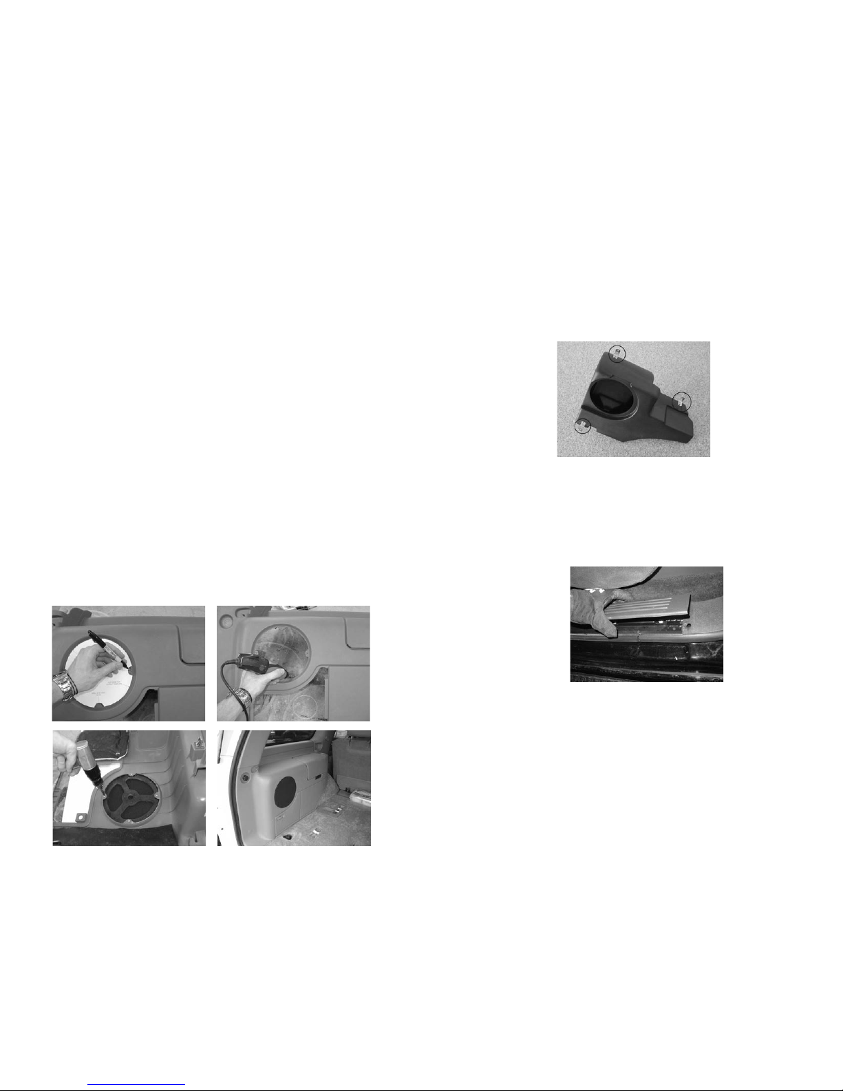
6. If your vehicle includes a factory installed woofer in this location it must be
uninstalled. Do this by unplugging the speaker wires, removing the two 10mm
bolts and lifting the enclosure up and out from the vehicle.
7. With the power screw driver and Phillips head bit, mount the included hard-
ware on your new subwoofer enclosure as shown below.
8. Place enclosure under the rear window, over the wheel well and secure in
place with the included hardware.
9. If externally amplified, make speaker connections to the enclosure from the
amplifier, positive to red terminal and negative to black terminal.
AMPLIFIED THUNDERFORM
Routing Power Wire; we recommend a connection directly to the battery.
10. Remove drivers' side and passengers' side threshold trim, pull up on trim,
it will remove easily.
11. Using furnished wiring harness route 10ga red power wire starting at pre-
amp location. Route wire to drivers' side, over to threshold and under carpet to
front of vehicle.
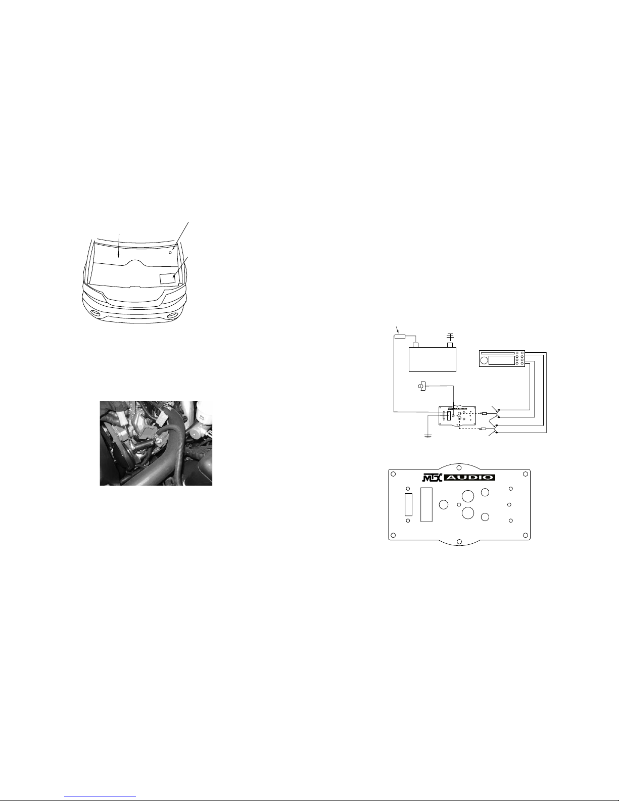
12. Open hood.
13. Drill a hole through the fire wall. Locate a spot low on the fire wall on the
passengers' side. You should always look to find a clear path. Drill a hole from
inside of the vehicle into the engine compartment and insert grommet. You may
also find a pre-existing, unused rubber grommet in this location that you can pass
the wire through.
Note: To avoid any damage to parts inside engine compartment, drill from
inside of vehicle using a short bit.
Setting Gain
Turn gain knob on ThunderForm pre-amp to minimum, counter clockwise.
Play a favorite tape or compact disc that contains consistent music and bass.
At this point, adjust Bass and Treble settings to neutral or flat. Turn the source
unit to maximum listening level. You should know that some source units will
produce distortion or "clip" before the unit reaches maximum volume. Reduce
volume to the loudest listening level before distortion. Turn the gain knob on the
ThunderForm pre-amp clockwise until the speaker starts to distort and reduce
gain to loudest listening level before distortion.
Optional- The EBC, or Electronic Bass Control, allows a remote bass control to
be adjusted from the drivers' seat.
Setting Crossover
You should set the crossover to your own personal listening taste. The cross-
over is adjustable to any frequency between 50Hz (counterclockwise) to 150Hz
(clockwise). As a guideline, the goal is to create the illusion of bass up front. The
higher the crossover point the more “audibly visible” your sub is going to be. Take
your time and really listen to your system, grab a soda and a few of your favorite
tunes and have fun.
TROUBLESHOOTING TIPS IF AMP DOES NOT TURN ON
Check all connections at battery and that fuse is installed
Check speaker wire connections
Check ground
Check fuse on pre-amp
25. To install the grill, use the included template to trace onto the panel. Carefully
cut out plastic leaving grill mounting tabs in place. Secure the grill from the back
side of panel with included screws. To avoid damage to panel or grill, do not over
tighten screws.
Before cutting, equip yourself with proper hand and face protection
25