MUELLER® Shur StopTM Unit 812 PE Line Stopping System
Operating Instructions
10 11
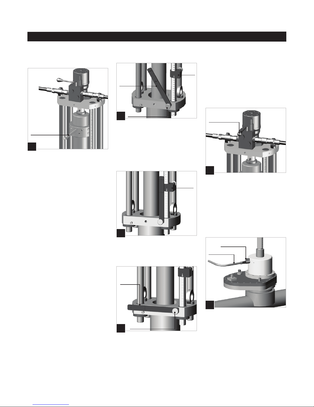
33. Carry out the cleaning operation
using the cleaning inspection
machine equipped with nylon wire
brush (N.).
34. Proceed with stopping operation.
35. Check the operation of the
expanding stopper. If the sealing
ring does not expand evenly on
the entire perimeter, it is necessary
to lubricate the walls surrounding
the ring with PURITY-FG Spray or
equivalent (walls are compressed
by two steel anges). Expand and
retract the sealing ring a few times
until the expansion is uniform. In the
event that the stopper is not used
for a long time, it is recommended to
completely disassemble the stopper,
replace the sealing ring and lubricate
thoroughly. After reassembling the
stopper, wipe the outer side of the
ring that comes into contact with the
inner side of the pipe.
36. Clean and lubricate the stopper
bar and the sealing disk to provide
smooth operation and to allow
centering of the stopper during the
expansion phase.
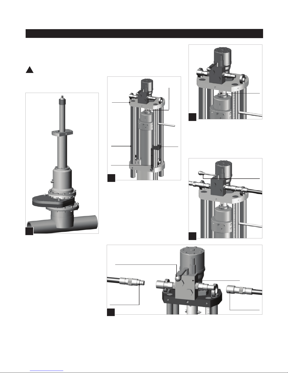
37. Position the stopping machine
(O.) on the slide gate valve.
NOTE: There are 2 handles on the
stopping machine. The longer one
should always be on the upstream
side.
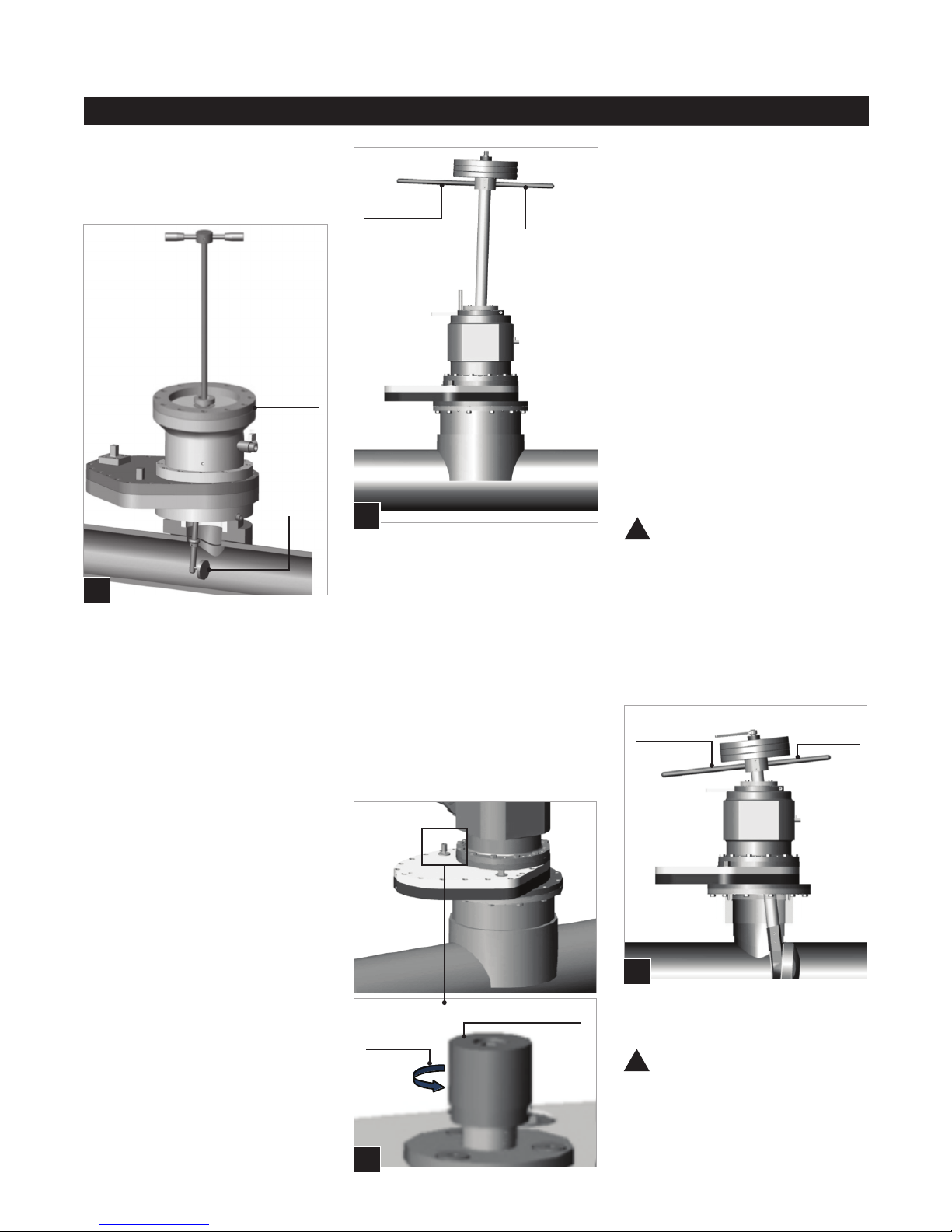
P.
Equalization Valve
Counter-
clockwise
42. Purge the air in the bypass
through the drain valve located on
the downstream stopping machine.
43. Open the second slide gate
valve without acting on the internal
pressure equalizer, as pressure is
already equal above and below the
gate.
44. Ensure the proper operation of
the bypass and check for leaks.
45. Leaving the safety ring loose,
lower the stopper and position the
long handle between the pins on the
saftey ring. If this is difcult, repeat
previous step taking care to ensure
the plug is at a 90° position with
respect to the pipe axis. Once the
hole has been passed, place the
plug in the direction of the pipe axis.
CAUTION: The plug should
never be inserted and expanded
on the upstream side.
46. Turn the ratchet handle
clockwise and gradually expand the
sealing ring of the stopper. During
this operation slide the rod from top
to bottom and vice versa to properly
position the stopper in the pipe (Q.).
47. Expand the sealing ring to
obtain a positive shut-off. DO NOT
overtighten.
CAUTION: The torque applied
to the ratchet spanner should not
exceed 52 ft-lb for the 8" plug.
The torque applied to the ratchet
spanner should not exceed 74 ft-lb
for the 12" plug.
38. Perform the same operations
on the second tting and install the
bypass between the two machines.
Equalize the pressure (P.) of the rst
slide gate valve. For this operation
rotate the knob that controls
equalizing valve counter-clockwise
until it stops.
39. Open the slide gate valve.
40. Open the machine bypass.
41. Open the machine bypass
located on the second stopping
machine.
!
!
O.
Long Handle Short
Handle
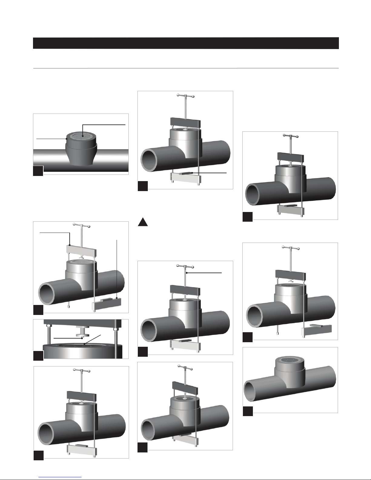
N.
Cleaning /
Inspection
Machine
with
Viewer
Brush
!
Q.
Long Handle Short
Handle