7
MUELLER®SUPER CENTURION®3 0 FIRE HYDRANT
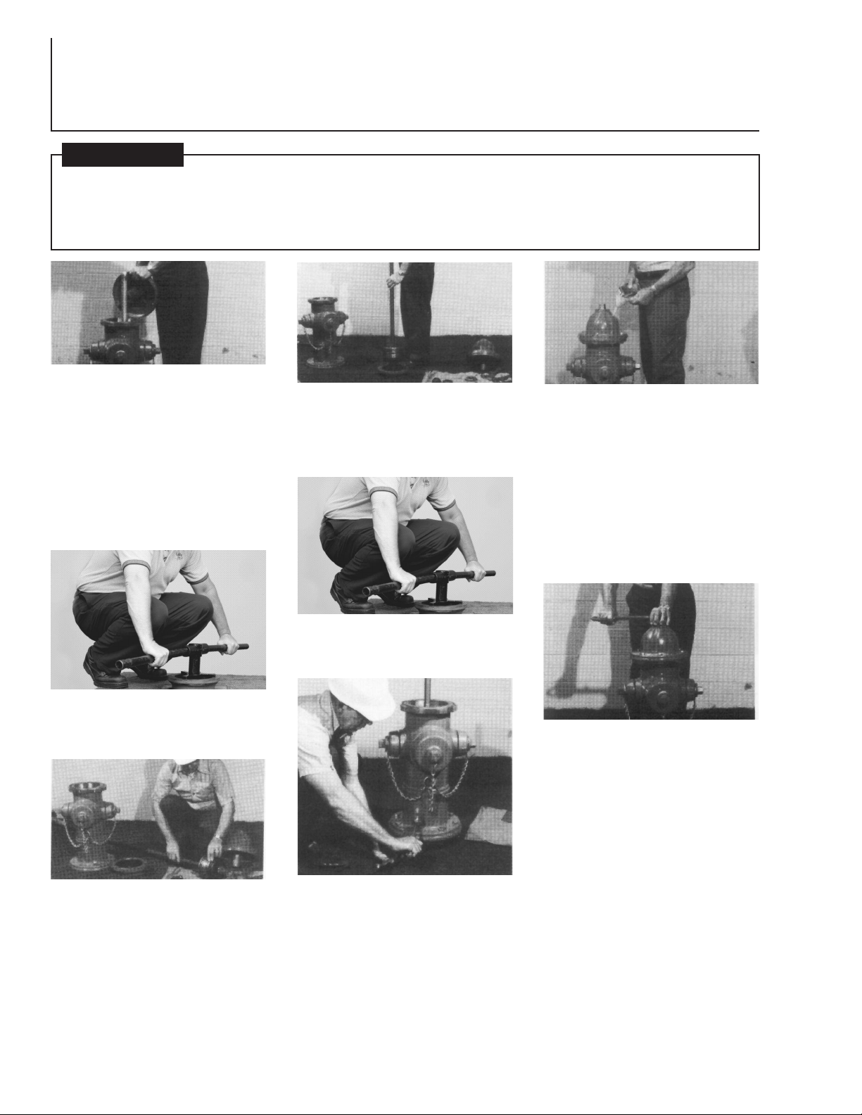
Remove Main Valve rom Lower Barrel Flange
CAUTION: Always fill the il reserv ir
with the b nnet installed, the hydrant
in its n rmal upright p siti n, and the
main valve fully cl sed. If the hydrant
is filled with lubricant under any ther
circum stances, excess lubricant can
ver fill the b nnet and create a pres -
sure l ck. This c uld result in damage
t the seals r b nnet, r prevent
pr per hydrant perati n.
1. Remove Hold Down Nut, Thrust Bearing, and
Operating Nut rom Bonnet. Lubricate Brass
Sleeve and slide over threaded stem end to
prevent O-ring damage. Unbolt and remove
Bonnet. Remove Sa ety Flange Bolts and Sa ety
Flange. Remove Upper Barrel. Remove Upper
Stem and Stem Coupling rom Lower Stem. Slide
slotted end o Wrench over Lower Stem. Align
holes in Wrench and Stem and attach Wrench to
Stem with Clevis Pin. Lower Support Arm onto the
Flange o Lower Barrel and tighten Thumb Screw
(to hold Main Valve in closed position). Shut o
water at Gate Valve.
5. Tighten Main Valve to 200 t-lbs. Turn on
water at the Gate Valve and remove Wrench
rom Stem by removing Clevis Pin.
8. Tighten Bonnet Bolts. Unscrew one Hose
Nozzle Cap slightly to bleed air. Open Hydrant
ully. Tighten the Hose Nozzle Cap when water
starts lowing and check all lange connections
or leaks. Turn Operating Nut to ully closed
position and remove Hose Nozzle Cap to allow
Barrel to drain. Replace Nozzle Cap.
9. Turn Operating Nut in closing direction to
make sure Main Valve is closed tightly, then
turn in opening direction approximately 1/4
turn to relieve tension on operating
mechanism.
2. Remove Main Valve Assembly by turning
Wrench counter-clockwise and li t out Wrench,
Lower Stem, Main Valve Assembly and Seat
Ring rom Hydrant Barrel as a unit.
6. Reassemble Upper Stem to Lower Stem.
Place Upper Barrel in place and reassemble
Sa ety Flange.**
4. Lower Main Valve Assembly and care ully
thread Seat Ring into the base o the Hydrant
hand-tight. Raise the Main Valve leaving about
1/2” o play between the Main Valve and Seat.
Lower Support Arm onto Flange o Lower
Barrel and tighten Thumb Screw.
3. Straighten stainless steel Lock Washer,
unscrew Cap Nut and remove Washer, Stem
Seal, Lower Valve Plate, Main Valve and Seat
Ring. Clean, inspect and replace any damaged
parts. (Main Valve can be reversed to provide
new seal.) Replace Drain Valve Facings. Inspect
and lubricate Top and Bottom Seat Ring O-
rings (replace i necessary). Lubricate all
threaded sur aces and reassemble. With Cap
Nut tightened to 100 t-lbs on 5 1/4” Hydrant,
or 75 t-lbs on 4 1/2” Hydrant, bend edges on
stainless steel Lock Washer over one lat on the
Lower Valve Plate and one lat on the Cap Nut.
7. Check Bonnet O-ring** or proper position and
condition. Attach the Brass Sleeve to Upper Stem
and lubricate outside to protect O-ring Seals rom
thread damage. Place Bonnet onto Upper Barrel
and assemble Bonnet Bolts only hand-tight.
Remove Brass Sleeve. Reassemble Operating Nut,
Thrust Bearing (re er to pg 1 or correct assembly),
and Hold Down Nut*. Be sure O-ring Seals are in
good condition at thread shoulder on outside o
Hold Down Nut and on inside where contact is
made with Operating Nut. Remove Oil Filler Plug
in side o Bonnet. Pour MUELLER Hydrant
Lubricant into Oil Reservoir until it is level with Oil
Filler Plug Hole. Replace Oil Filler Plug.
Bef re rem ving any b lt(s) h lding the hydrant t gether, shut ff gate valve t is late hydrant fr m main water s urce.
L sen (d n t rem ve) ne n zzle cap tw turns and check f r water under pressure inside hydrant – bleed ff any pressure,
then rem ve n zzle cap c mpletely. Open hydrant main valve c mpletely. A c ntinu us fl w f water, n matter h w slight,
indicates hydrant is n t pr perly is lated fr m the main water supply, and that pr blem must be c rrected bef re any
hydrant disassembly can pr ceed. Disassembly f hydrant with pressurized water acting against the main valve c uld result
in unexpected ejecti n f hydrant parts, debris r high-pressure water stream, which c uld cause seri us b dily injury.
! WARNING
*TIGHTEN HOLD DOWN NUT TO 200-300
FT-LBS OF TORQUE. IF TORQUE WRENCH IS
NOT AVAILABLE, USE A 3 LB HAMMER TO
STRIKE THE END OF THE A-311 WRENCH
FIRMLY TWO TIMES TO ASSURE THE NUT IS
PROPERLY TIGHTENED.
**TO DETERMINE CORRECT O-RINGS FOR
BONNET AND GROUND LINE FLANGES,
WHICH ARE SIMILAR IN APPEARANCE: SMALLER
DIAMETER O-RING IS USED AT BONNET
FLANGE; LARGER AT GROUND LINE FLANGE.