INSTALLATION INSTRUCTIONS
SENTRYX™SOFTWARE ENABLED
SUPER CENTURION®
PRIOR-TO FIELD WORK
• Access to the Sentryx website is required to complete this
installation. If you do not have a user account or cannot log in, please
contact your site administrator. [Alerts from the Sentryx platform
will be provided for (a) coverage strength feedback in the "Field
Work" section and (b) "success" in Section 36. In order to receive
alerts, you need to create a Sentryx account (with current email
address and cell number provided), select email and/or text alerts,
and bring an electronic device to receive these alerts into the field.]
• Before installation, visit each potential site and verify G LTE CAT
M coverage. Reference the Mueller Cellular Signal Strength guide
(F14334).
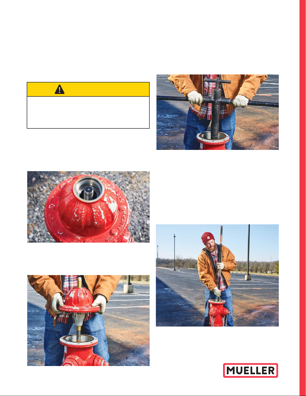
FIELD WORK
For Retrofit Kit
• Signal Strength:
– Prior to disassembly of installed hydrant, confirm cell coverage at
site of installation.
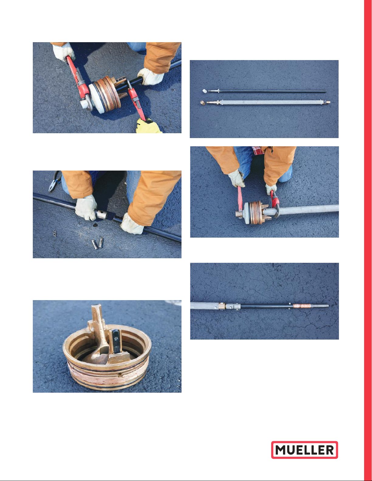
– Hold the new bonnet near the same height and location of
installation.
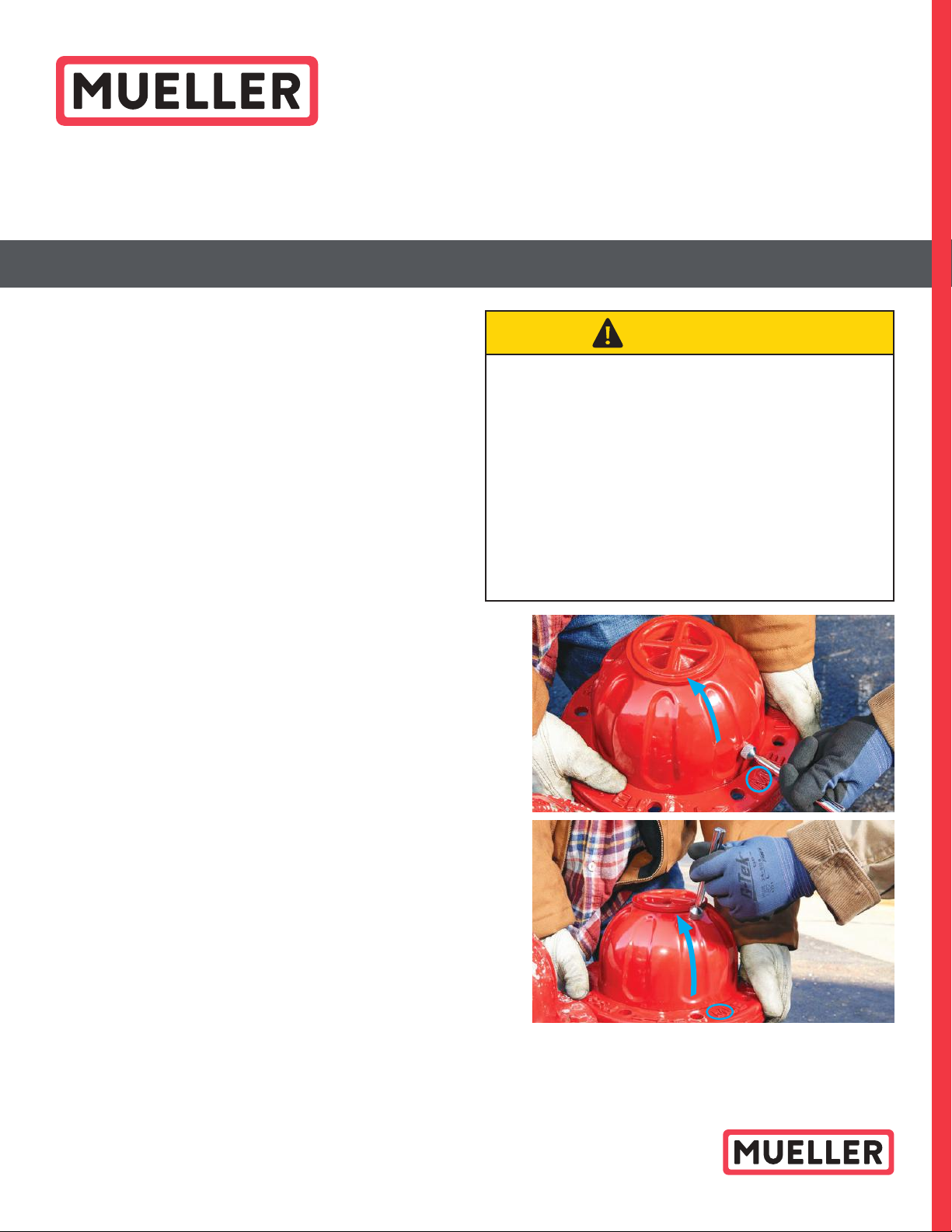
– Place the commissioning tool close to the bonnet, approximately
1/4˝ away, above ˝M˝ on the seal plate flange, while keeping away
from iron parts. (Reference to the right ).
– Move the commissioning tool up along the curve of the bonnet
keeping it approximately 1/4˝ away from the surface. This action
will cause the bonnet to awaken and search for a connection.
If the bonnet does not establish a connection (i.e. no Sentryx
alert is provided within 5 minutes), select a different location.
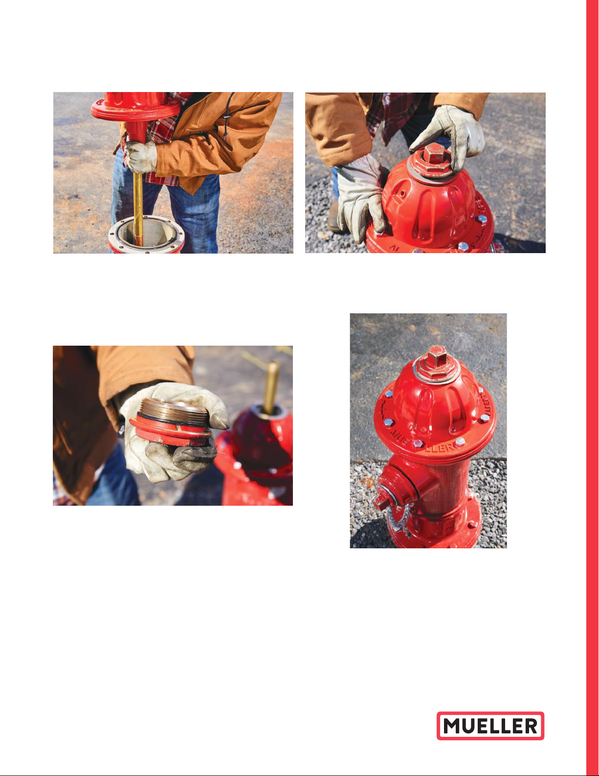
– Once a connection is established, the Sentryx platform will
send out an email and/or text message (Depending on initial
configuration) displaying the signal strength. See Appendix A.
If message indicates a weak signal, select a different location.
If message indicates a strong signal, proceed through
instructions below.
Note: Caution: Changes or modifications not expressly approved by Mueller Systems, LLC could void the user's authority to operate the equipment. This equipment has been tested and found to comply
with the limits for a Class B digital device, pursuant to part 15 of the FCC Rules. These limits are designed to provide reasonable protection against harmful interference in a residential installation. This
equipment generates, uses and can radiate radio frequency energy and, if not installed and used in accordance with the instructions, may cause harmful interference to radio communications. However,
there is no guarantee that interference will not occur in a particular installation. If this equipment does cause harmful interference to radio or television reception, which can be determined by turning the
equipment off and on, the user is encouraged to try to correct the interference by one or more of the following measures:
– Reorient or relocate the receiving antenna.
– Increase the separation between the equipment and receiver.
– Connect the equipment into an outlet on a circuit different from that to which the receiver is connected.
– Consult the dealer or an experienced radio/TV technician for help.
This device complies with part 15 of the FCC Rules. Operation is subject to the following two conditions: (1) This device may not cause harmful interference,
and (2) this device must accept any interference received, including interference that may cause undesired operation.
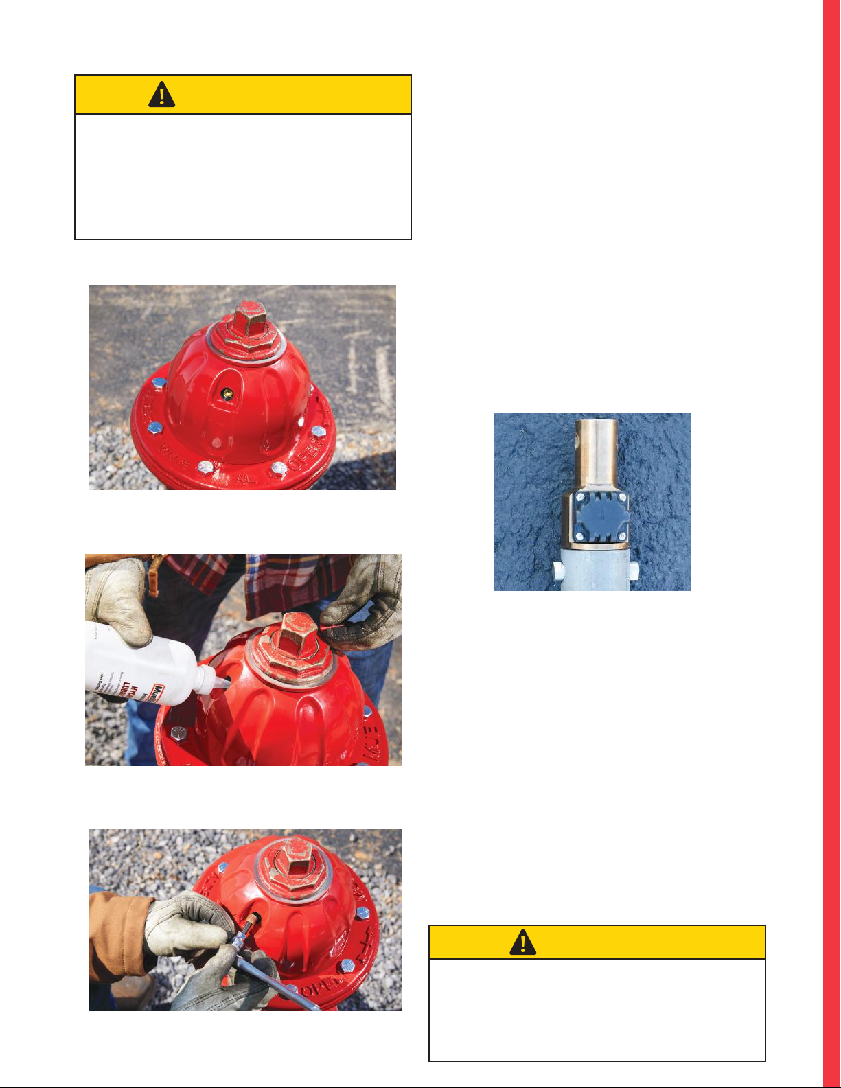
CAUTION
COMPLY WITH ALL REQUIRED INDUSTRY, SITE, STATE, AND
FEDERAL SAFETY REQUIREMENTS
DO NOT DROP NEW HYDRANT LOWER STEM OR NEW
BONNET ASSEMBLY. DAMAGE MAY OCCUR.
THE ANTENNA ON THE STEM CAN BE DAMAGED BY A
FORCEFUL IMPACT FROM A SEAT WRENCH – UTILIZE CARE.
SENTRYX SOFTWARE ENABLED SUPER CENTURION
IS DESIGNED TO WORK WITH MUELLER OEM PARTS ONLY.
AVOID BACKFILLING OVER EXPOSED BONNET AS DAMAGE
TO PAINT MAY OCCUR