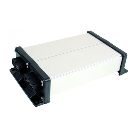
Muller Elektronik SPRAYER-Controller Orchard/Vineyard MIDI 3.0 User manual

Installation and operating instructions
SPRAYER-Controller Orchard/Vineyard MIDI 3.0
Version: V1.20190404
3030383000-02-EN Read and follow these operating instructions.
Keep these operating instructions in a safe place for later
reference.

Company details
Installation and operating instructions
Product: SPRAYER-Controller Orchard/Vineyard MIDI 3.0
Document number: 3030383000-02-EN
As of software version: 01.01.04.00
Original language: German
Müller-Elektronik GmbH & Co.KG
Franz-Kleine-Straße 18
33154 Salzkotten
Germany
Phone: ++49 (0) 5258 / 9834 - 0
Fax: ++49 (0) 5258 / 9834 - 90
Email: info@mueller-elektronik.de
Homepage: http://www.mueller-elektronik.de
Document
Copyright ©

Table of contents
3030383000-02-EN
V1.20190404
3
Table of contents
1
For your safety
6
1.1
Basic safety instructions
6
1.2
Intended use
6
1.3
Layout and meaning of warnings
7
1.4
User requirements
7
1.5
Safety stickers on the product
7
1.6
Disposal
8
1.7
EU declaration of conformity
8
2
About these Operating Instructions
9
2.1
Who should read these instructions?
9
2.2
Directional information in these instructions
9
2.3
Layout of operating instructions
9
2.4
Layout of references
10
3
About the job computer
11
3.1
Job computer functions
11
3.2
System overview
11
3.3
Rating plate
12
4
Mounting and installation
13
4.1
Installing the job computer
13
4.1.1
Instructions for safe installation
13
4.1.2
Connecting the AMP connectors
13
4.1.3
Separating the AMP connectors
14
4.2
Connecting the job computer to the ISOBUS
14
4.3
Installing the junction box
15
4.3.1
Connecting the sensors and actuators to the junction box
15
4.3.2
Inserting the cable core into a terminal
16
4.3.3
Connecting the junction box to the job computer
16
5
Basic control principles
17
5.1
Switching on the job computer
17
5.2
Layout of work screen
17
5.2.1
Spray data area
18
5.2.2
Boom display area
20
5.2.3
Icons beside the implement image
22
5.3
Navigation in the software
23
5.4
Control units
24
6
Operating job computer on the field
25
6.1
Tank filling
25
6.2
Controlling the boom
26

Table of contents
4
V1.20190404
3030383000-02-EN
6.2.1
Raising and lowering the air cushions
26
6.2.2
Lifting and lowering the boom
26
6.2.3
Folding and unfolding the boom
27
6.2.4
Extending and retracting the boom
29
6.3
Starting application
29
6.4
Regulating the application rate
30
6.4.1
Changing the application rate in manual mode
30
6.4.2
Using Automatic mode
31
6.4.3
Setting target rate
32
6.4.4
Stopping application
33
6.5
Operating sections
33
6.6
Operating the spraying area via the boom display
33
6.7
Adjusting the chassis
34
6.7.1
Adjusting the axles
34
6.7.2
Sloping the implement
35
6.8
Documenting work results
35
6.9
Switching the fans on and off
36
6.10
Switching the air compressor on and off
36
6.11
Operating the ME joystick
37
6.11.1
Preview mode for the ME Joystick
38
6.11.2
Viewing the assignment of the joystick
38
6.12
Operating additional functions
39
7
Configuring the job computer
40
7.1
Entering sprayer parameters
40
7.1.1
“Target Rate” parameter
40
7.1.2
“Product” parameter
40
7.1.3
“Working Width” parameter
40
7.1.4
“Wheel Impulses” parameter
40
7.1.5
“Minimum Pressure” parameter
40
7.1.6
“Maximum Pressure” parameter
41
7.1.7
“Sprayer off Below” parameter
41
7.1.8
“Regulation off Below” parameter
41
7.1.9
“Regulation Factor” parameter
41
7.1.10
“Tank Size” parameter
41
7.1.11
“Tank level alarm” parameter
42
7.1.12
“Impulses Main Flow” parameter
42
7.1.13
“Circulation Type” parameter
42
7.2
Configuring the control units
42
7.3
Calibrating the flow meter
43
7.3.1
Calibrating the flow meter with the tank method
43
7.3.2
Calibrating the flow meter with the nozzle method
45
7.3.3
Manually entering the number of impulses per liter for the flow meter
47
7.4
Configuring products
47
7.5
Selecting and configuring the speed sensor
47
7.5.1
Selecting the speed source
47
7.5.2
Calibrating the speed sensor with the 100m method
48

Table of contents
3030383000-02-EN
V1.20190404
5
7.5.3
Configuring the reverse driving sensor
49
7.5.4
“Simulated Speed” function
49
7.6
Configuring the nozzles - for sprayers with pressure calculation
50
7.6.1
Nozzle assistant
50
7.6.2
Calibrate the nozzles
52
7.7
Configuring the sides and sections
53
7.7.1
Configuring the number of sides and sections
53
7.7.2
Pre-configuring the row spacings
53
7.7.3
Switching sections off permanently
54
7.7.4
System delay when switching the sections
54
“Delay on Start” parameter
55
“Delay on Stop” parameter
55
7.7.5
Changing the display of areas on the terminal
55
7.8
Entering the sprayer geometry
56
7.9
Assigning the joystick buttons
56
8
Troubleshooting
57
8.1
Alarm messages
57
8.2
Checking the software version
57
9
Technical specifications
58
9.1
Technical specifications of the job computer
58
9.2
Available languages
58

1
For your safety
Basic safety instructions
6
V1.20190404
3030383000-02-EN
For your safety
Basic safety instructions
Operation
Be sure to always comply with the following instructions during operation:
▪Before you leave the vehicle cab, ensure that all automatic mechanisms are deactivated or
manual mode is activated.
▪Keep children away from the implement and the job computer.
▪Carefully read and follow all safety instructions in this operating guide and in the machine
operating instructions.
▪Observe all applicable regulations on accident prevention.
▪Follow all recognised safety, industrial and medical rules as well as all road traffic laws.
▪Use only clear water when you are testing the sprayer. Do not use a poisonous spray during the
tests or when calibrating the systems.
Servicing
Keep the system in a functional condition. To do so, follow these instructions:
▪Do not make any unauthorized modifications to the product. Unauthorized modifications or use
may impair safety and reduce the service life or operability of the unit. Modifications are
considered unauthorized if they are not described in the product documentation.
▪Never remove any safety mechanisms or stickers from the product.
▪Before charging the tractor battery, always disconnect the tractor from the job computer.
▪Before performing any welding on the tractor or the implement, always disconnect the power
supply to the job computer.
▪The job computer and the cabling must not be repaired. Unauthorised attempts at repairs can fail
and cause hazardous malfunctions.
▪Use only original accessories as spare parts.
Intended use
The product is only intended for use in the agricultural sector. The manufacturer is not liable for any
other installation or use of the product.
The manufacturer cannot be held liable for any personal injury or property damage resulting from
such non-compliance. All risk arising from improper use lies with the user.
Intended use also includes compliance with the conditions for operation and repairs prescribed by the
manufacturer.
All applicable accident prevention regulations and all other generally recognized safety, industrial,
and medical standards as well as all road traffic laws must be observed. Any unauthorized
modifications made to the equipment will void the manufacturer's warranty.
1
1.1
1.2

For your safety
Layout and meaning of warnings 1
3030383000-02-EN
V1.20190404
7
Layout and meaning of warnings
All safety instructions found in these Operating Instructions are composed in accordance with the
following pattern:
WARNING
This signal word identifies medium-risk hazards, which could potentially cause death or serious
physical injury, if not avoided.
CAUTION
This signal word identifies hazards that could potentially cause minor or moderate physical injury or
damage to property, if not avoided.
NOTICE
This signal word identifies hazards that could potentially cause damage to property, if not avoided.
There are some actions that need to be performed in several steps. If there is a risk involved in
carrying out any of these steps, a safety warning appears in the instructions themselves.
Safety instructions always directly precede the step involving risk and can be identified by their bold
font type and a signal word.
1. NOTICE! This is a notice. It warns that there is a risk involved in the next step.
2. Step involving risk.
User requirements
▪Learn to operate the product in accordance with the instructions. Nobody must operate the
product before reading these instructions.
▪Please read and carefully observe all safety instructions and warnings contained in these
Operating Instructions and in the manuals of any connected vehicles and farm equipment.
▪If there is anything within these instructions that you do not understand, please do not hesitate to
contact us or your dealer. Müller-Elektronik's Customer Services department will be happy to
assist you.
Safety stickers on the product
Sticker on the job computer
Do not clean with a high-pressure cleaner.
1.3
Example
1.4
1.5

1
For your safety
Disposal
8
V1.20190404
3030383000-02-EN
Disposal
When it has reached the end of its service life, please dispose of this product as
electronic scrap in accordance with all applicable waste management laws.
EU declaration of conformity
Herewith we declare that the design and construction of this product and its identical variants, as well
as the form brought onto the market by us, is in accordance with the relevant safety and health
requirements of the EU Directive of Electromagnetic Compatibility 2014/30/EU. If alterations are
made to the product without prior consultations with us, this declaration becomes invalid.
MIDI 3.0 job computer
Harmonised standards applied: EN ISO 14982:2009
(EMC Directive 2014/30/EU)
In conformity with further EU directives:
Directive 2011/65/EU (RoHS 2)
1.6
1.7

About these Operating Instructions
Who should read these instructions? 2
3030383000-02-EN
V1.20190404
9
About these Operating Instructions
Who should read these instructions?
These instructions are intended for operators of orchard or vineyard sprayers equipped with a job
computer from Müller-Elektronik.
The instructions will show you:
▪The meaning of the icons on the screen;
▪Where to find the settings that are relevant for a function in the application;
▪How to configure the application;
▪How to calibrate components that need to be calibrated.
The instructions do not explain how to operate the orchard or vineyard sprayer. It is not a substitute
for the orchard/vineyard sprayer manufacturer's instruction manual.
Directional information in these instructions
All directional information in these instructions, such as “left”, “right”, “forward”, “back”, is relative to
the movement direction of the vehicle.
Layout of operating instructions
The operating instructions explain step by step how you can perform certain operations with the
product.
We use the following symbols throughout these Operating Instructions to identify different operating
instructions:
Type of depiction
Meaning
1.
2.
Actions that must be performed in succession.
⇨
Result of the action.
This will happen when you perform an action.
⇨
Result of an operating instruction.
This will happen when you have completed all
steps.
Requirements.
In the event that any requirements have been
specified, these must be met before an action
can be performed.
2
2.1
2.2
2.3

2
About these Operating Instructions
Layout of references
10
V1.20190404
3030383000-02-EN
Layout of references
If any references are given in these Operating Instructions, they appear as:
Example of a reference: [➙10]
References can be identified by their square brackets and an arrow. The number following the arrow
shows you on what page the section starts where you can find further information.
2.4

About the job computer
Job computer functions 3
3030383000-02-EN
V1.20190404
11
About the job computer
Job computer functions
The SPRAYER-Controller Orchard/Vineyard MIDI 3.0 job computer is an ISOBUS job computer that
can control the operation of orchard or vineyard sprayers.
The ISOBUS job computer is the switching central of the orchard or vineyard sprayer. Several
sensors are connected to the job computer, which monitor important implement parts. The job
computer controls the implement based on these signals and on the operator's specifications. An
ISOBUS terminal serves as an interface. All implement-specific data is stored in the job computer and
is therefore maintained even when changing the terminal.
System overview
The system consists of one or several job computers that are mounted on the orchard or vineyard
sprayer and control the operation.
Small system with one job computer
ECU-Midi job computer Junction box
ISOBUS cable
CAN termination
3
3.1
3.2

3
About the job computer
Rating plate
12
V1.20190404
3030383000-02-EN
Large system with two job computers
ECU-MIDI master job computer
CAN termination
ISOBUS cable
Master junction box
Connecting cable between the job computers
Slave junction box
ECU-MIDI slave job computer
Each job computer is responsible for controlling selected functions of the orchard or vineyard sprayer
and receives signals from selected sensors. For systems with two or more job computers, each uses
identical job computers and junction boxes.
Rating plate
Abbreviations on the rating plate
Abbreviation
Meaning
Customer number
If the product was manufactured for an agricultural machinery
manufacturer, the agricultural machinery manufacturer's item number
will be shown here.
Hardware version
Müller-Elektronik item number
Operating voltage
The product may only be connected to voltages within this range.
Software version upon delivery
Serial number
3.3

Mounting and installation
Installing the job computer 4
3030383000-02-EN
V1.20190404
13
Mounting and installation
Installing the job computer
Instructions for safe installation
To prevent damage to the system components, consider the following during installation:
▪Install the job computer where it is protected from dirt. You therefore avoid unintentional cleaning
of the job computer by the implement operator using a high-pressure cleaner.
▪In the installed position, the connectors and the pressure compensation membrane must be
facing to the side.
▪Fasten the job computer with four fixing bolts and a flat washer (lock washers can cause cracks
in the plastic on the long term) on a conducting spot on the implement chassis. In case of
improper installation, the ESD discharges can cause malfunctions.
▪All of the sockets and connectors that are not used must be protected from dust and water using
suitable dummy connectors.
▪All of the connectors must be tightly sealed. This makes them waterproof.
▪Do not use the system if some of its parts are damaged. Damaged parts can cause malfunctions
and lead to injuries. Replace damaged components or repair them if possible.
▪Use only original components manufactured by Müller-Elektronik.
Connecting the AMP connectors
This is how to connect two AMP connectors:
1. Pull out the red locking device of the AMP socket all the way to the end.
⇨You will hear a loud clicking sound.
⇨The openings for inserting the locking pins of the connector are visible.
2. Insert the connector into the socket. It should be possible to easily insert the locking pins in the
openings.
⇨The connector is loosely inserted in the socket.
3. Press in the red locking device.
⇨You will hear a loud clicking sound.
⇨A part of the locking device comes through to the other side of the socket.
4
4.1
4.1.1
4.1.2
Procedure

4
Mounting and installation
Connecting the job computer to the ISOBUS
14
V1.20190404
3030383000-02-EN
⇨You have connected and locked the connector with the socket.
Separating the AMP connectors
This is how to separate two AMP connectors:
1. Press in both ends of the red locking device in direction of the connector.
⇨You will hear a loud clicking sound.
⇨The locking device has been released.
2. Pull out the red locking device of the AMP socket all the way to the end.
3. Pull the connector out of the socket.
Connecting the job computer to the ISOBUS
To connect the job computer to the power supply and to the ISOBUS terminal, you have to connect
the ISOBUS cable to an ISOBUS power socket on the tractor.
This is how to connect the job computer to the ISOBUS:
1. Take the ISOBUS cable from the job computer.
2. Unscrew the dust protection cap.
⇨
3. Insert the ISOBUS connector into the ISOBUS power socket on the tractor.
4. Lock the connector. For basic vehicle harnesses from Müller-Elektronik, turn the connector
clockwise. For other ISOBUS basic vehicle harnesses, the procedure depends on the model.
⇨The connector fits tightly.
5. Screw the dust protection cap of the connector and the socket together.
4.1.3
Procedure
4.2
Procedure

Mounting and installation
Installing the junction box 4
3030383000-02-EN
V1.20190404
15
⇨
6. When the work is completed, separate the connection and screw the dust protection cap back
on.
⇨
Installing the junction box
Take note of the following when selecting the installation location:
▪Ensure that cables cannot be damaged by the moving implement.
▪The cable glands must be facing downwards.
Connecting the sensors and actuators to the junction box
Every sensor and every actuator that is mentioned in the pin-out diagram must be connected to the
junction box mentioned in the pin-out diagram.
This can be done in two ways:
▪The sensor or actuator ends with a short cable and an AMP connector.
In this case, you will receive a fitting extension cable for each sensor. You must insert the
extension cable in the junction box and connect it to the fitting terminal.
▪The sensor or actuator ends with a long cable without a connector. You have to insert it in the
junction box and connect it to the fitting terminal.
The terminal to which you must connect the cable core depends on the respective implement and on
the type of sensor or actuator.
Please note that the cable cores for the ultrasonic sensor trigger always need to be connected to Pins
2 and 3.
NOTICE
Risk of short-circuit
When exchanging the polarity of cable cores, machine sensors can be damaged by a short-circuit.
◦Pay attention to the polarity of the cable cores and the terminals.
The junction box is not powered.
There is no voltage on the components to be connected.
1. Remove the cable coating so that all cable cores are exposed.
4.3
4.3.1
Procedure

4
Mounting and installation
Installing the junction box
16
V1.20190404
3030383000-02-EN
2. Insert the cable to the end of the coat. There should only be cable cores inside the junction box.
The cable coating must end at the junction box casing. This is the only way to ensure that you
have enough space in the junction box to be able to guide all of the cable cores to the terminals.
3. Remove the cable coating of the cable cores ca. 1 cm from the end of the cable core.
4. CAUTION! Pay attention to the proper polarity of the cable cores and the terminals.
5. Connect the cable cores to the terminals.
To do so, use the information on the lid of the junction box, on the relay circuit board and in the
pin-out diagram.
6. With screw terminals, use wire end sleeves. Wire end sleeves may not be used with spring-
loaded terminal blocks.
7. Close the screw connections of the junction box.
After screwing them shut, the glands should be sealed.
8. Close unused openings in the casing of the junction box with blind caps.
Inserting the cable core into a terminal
Each terminal consists of two openings:
▪The upper opening of the terminal opens the lower opening.
▪The bottom opening of the terminal serves to insert and clamp one cable core.
You have prepared a small flat screwdriver that fits the upper opening of the terminal. You only
need this screwdriver if there are no wire end sleeves on the cable cores.
You have cut the cable to the proper length and have exposed the cable cores according to the
instructions, or you have a finished cable from Müller Elektronik.
The tractor engine is switched off.
The junction box is not powered.
There is no voltage on the components to be connected.
1. Find the proper connectors for the cable cores to be connected.
To do so, use the information on the lid of the junction box, on the relay circuit board and in the
pin-out diagram.
2. Insert the cable core into the opening in the lower part of the terminal. If you are not using wire
end sleeves, you first have to use the screwdriver.
⇨The cable core will be held by the terminal.
⇨You have clamped the cable core.
Connecting the junction box to the job computer
1. Connect the AMP connector of the junction box onto the proper job computer.
4.3.2
Procedure
4.3.3
Procedure

Basic control principles
Switching on the job computer 5
3030383000-02-EN
V1.20190404
17
Basic control principles
Switching on the job computer
1. Connect the ISOBUS cable of the job computer to the ISOBUS connector on the tractor.
2. Start the ISOBUS terminal.
⇨The job computer is started together with the terminal.
⇨When starting up for the first time, the job computer initially has to transmit lots of
information to the terminal. This can take a few minutes.
⇨When all of the data from the job computer application has been loaded, their icon appears
on the terminal: .
3. Open the job computer application. To do so, follow the instruction for the ISOBUS terminal.
⇨The work screen of the job computer appears.
Layout of work screen
The work screen is always shown during operation and informs you of the status of the orchard or
vineyard sprayer.
The work screen is divided into several areas. In each area, information on specific topics may
appear.
When configuring the job computer, the areas can be changed for a orchard or vineyard sprayer
model from a specific manufacturer. For this reason, the following graphs only show the standard
version of the overview.
Areas on the work screen
“Spray data” area “Boom display” area with icons beside the
implement image
You can read about the information that appears in these areas in the following sections.
Function icons appear beside the work screen, which perform functions when they are tapped. Their
position and operation depend on the type of ISOBUS terminal.
In the table below, you can see the meaning of the function icons on the work screen.
5
5.1
Procedure
5.2

5
Basic control principles
Layout of work screen
18
V1.20190404
3030383000-02-EN
Function icon
Function
Opens the “Results” screen.
Opens the “Parameters” screen.
Opens the “Tank Filling” screen.
Opens the “Folding” screen.
Switches between manual and automatic regulation of the application rate.
Opens a screen with additional functions.
Activates or deactivates operation of the spraying areas.
Opens the “ME-Joystick” screen.
/
Switches between two levels of icons.
Shows the next page with function icons.
Spray data area
The following information is shown in this area:
Selected icons in the spray data area
Depending on the configuration, the following icons may appear:
Icon
Meaning
The application rate will be automatically regulated.
The current value (current application rate) appears next to it.
No flow. The main valve cannot be opened because one of the
requirements has not been fulfilled:
- Speed slower than “Sprayer off below” [
➙
41]
5.2.1
Icons

Basic control principles
Layout of work screen 5
3030383000-02-EN
V1.20190404
19
Icon
Meaning
- Section status
- Target rate out of reach
- SECTION-Control has terminated the application
The application rate will be automatically regulated.
The target rate appears next to it.
See: Using Automatic mode [
➙
31]
The application rate will be manually regulated.
See: Changing the application rate in manual mode [
➙
30]
The bar graph only appears when the target rate is changed in automatic
mode using the +10% and -10% buttons. It shows the deviation from the
original target rate.
Automatic mode is deactivated. The flow will not be regulated.
The current speed is lower than the “Regulation off below” [➙41]
parameter and higher than “Sprayer off below” [
➙
41]
The target rate is defined by an external source: Task Controller,
prescription map, external sensor etc. See: Setting target rate [➙32]
- A problem has occurred with the transmission of the target rate from an
external source.
- The sprayer is outside of the area defined in the prescription map or in an
area that should not be sprayed.
The sprayer functions will be switched on and off through an “S-Box”.
Trip counter is deactivated
See: Documenting work results [
➙
35]
Speed
If the numbers are red, it means that the regulation or the application have
been interrupted because the speed is too low.
/
(background is
flashing)
The speed signal from the tractor / ISOBUS cannot be adopted. The system
will now determine the speed using the sensor connected to the junction
box.
Ensure that the number of impulses per 100m is correctly entered.
The icon can only appear if the signal source was automatically selected.
The vehicle is driving in reverse.

5
Basic control principles
Layout of work screen
20
V1.20190404
3030383000-02-EN
Icon
Meaning
Simulated speed activated. [➙49]
Pressure
Boom display area
In the boom display you find the following information:
▪Number of sections
▪Which sections are preselected or switched off
▪Which sections are applying
The diagrams below show how the sections may appear in the boom display area:
Sections 1 and 2 are closed and deactivated.
Sections 1 and 2 are closed. All of the other sections are open and spraying.
When SECTION-Control is activated, the blue-red SECTION-Control icon also appears.
5.2.2
Illustration
Other manuals for SPRAYER-Controller Orchard/Vineyard MIDI 3.0
1
This manual suits for next models
2
Table of contents
Other Muller Elektronik Controllers manuals
Popular Controllers manuals by other brands

X10
X10 MC460 owner's manual

Sminn
Sminn BOX S 220 instruction manual

LS
LS XBF-AD04C installation guide

YASKAWA
YASKAWA OYMC V1000 Programming manual

Federal Signal Corporation
Federal Signal Corporation PAGASYS GEN II Description, Installation, and User Manual

SUPERIOR CONTROLS
SUPERIOR CONTROLS STERLING CONTROLLERS owner's manual