manuals.online logo
Brands
  1. Home
  2. •
  3. Brands
  4. •
  5. Johnson Controls
  6. •
  7. Controllers
  8. •
  9. Johnson Controls V-4000-1 User manual

Johnson Controls V-4000-1 User manual

14- 880- 125, Rev. B
Product Bulletin V-4000
Issue Date April 2016
© 2016 Johnson Controls, Inc. 1
Part No. 14-880-125 Rev. B
Code No. LIT-977255
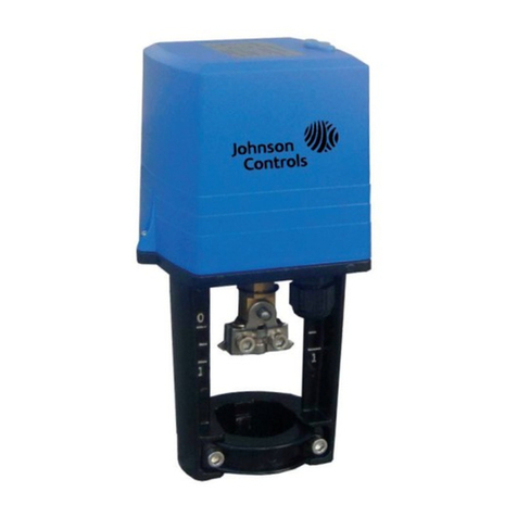
The V-4000-1 Small Pneumatic Actuator is
designed to position modulating plugs of chilled or
hot water (up to 200° F) control valves accurately
in response to a pneumatic signal from a
controller. It is tailored for small terminal unit valve
applications, and can be used on Johnson
Controls brass valves as a direct replacement for
oval top actuators (VT Series and oval top series).
Figure 1: V-4000-1
V-4000 Small Pneumatic Actuator for Small Control
Brass Valves
Features and Benefits
Directly replaces field installed
V-3854 and V-3800 models Simple, low-cost upgrade
Glass-reinforced nylon housing Long lasting and corrosion resistant
Compact design Fits in tight mounting spaces
Easy-mount design Requires no tools for mounting, even in "blind"
installations
Low cost Repairs by unit replacement
Snap-on mounting with retaining
nut Assures correct alignment
Pneumatic connection readily
positioned for easy access Simplifies tubing routing
2 V-4000 Small Pneumatic Actuator for Small Control Brass Valves
Application Overview
The V-4000-1 is designed for use with Johnson
Controls small brass valves—normally open,
normally closed, and three-way mixing valve
styles.
The Small Pneumatic Actuator (V-4000-1) is
designed with a snap-on, hand tightened
mounting that uses no set screws and requires
no tools. It is designed to field replace oval-top
and other actuators installed on V-3854, V-3800,
and other valves.
Operating Principles
Air pressure from a pneumatic controller is
applied to the diaphragm of the actuator, which
moves a piston against the valve stem. The
piston will move the valve stem and plug until the
diaphragm pressure balances the valve return
spring force and the fluid forces. These fluid
forces will cause the operating range to shift
from the nominal spring range. Reducing the air
pressure to the diaphragm of the actuator allows
the spring to return the valve plug to its normal
position.
This actuator is based on a rolling diaphragm
design. The rolling diaphragm provides a
constant effective area throughout the valve
stem stroke. The actuator housing is
constructed of sturdy, glass-reinforced nylon.
Due to the simplicity of the design, it is more
economical to replace the actuator than to repair
it. Therefore, no repair parts are needed or
provided.
Installation Instructions
Assembling the actuator. No tools are
required for this operation.
1. Before mounting the actuator to the valve,
locate the retaining nut in the full up position,
completely disengaged from the yoke
threads (Figure 5).
Note: The actuator cannot be mounted or
removed if the retaining nut is located on
the yoke threads.
2. The actuator can be mounted on cage trim
or VT valves:
 If the actuator is to be assembled to a
VT valve, insure that the plastic spring
seat retainer is in place (Figure 5). Use
the retainer furnished with the actuator if
there is no retainer in the valve. Insert
the retainer so that the projection at the
bottom of the retainer snaps into the
keyway at the bottom of the spring seat.
When properly inserted, the top of the
retainer will be below the top of the
spring seat.
If the actuator is being mounted on a
cage trim valve, check the spring gauge
height before mounting the actuator.
This measurement cannot exceed
1-13/16 inches (46 mm) as shown in
Figure 5. If the gauge height is greater
than 1-13/16 inches (46 mm), adjust it to
this value.
3. Tilt the actuator and slide it over the valve
spring as shown in Figure 2.
4. Tilt the actuator slightly, and snap the yoke
over the valve bonnet as shown in Figures 3
and 4.
5. Rotate top of actuator so that the air fitting is
in the desired position.
6. Secure the actuator to the valve by turning
the retaining nut onto the yoke threads.
While holding the actuator in position, turn
down the nut until it no longer turns freely.
Then tighten by hand one additional turn.
!
CAUTION: Hand tighten nut only —
do not use tools.
V-4000 Small Pneumatic Actuator for Small Control Brass Valves 3
Removing the actuator
1. Remove the polytubing from the barb. The
tube may have to be cut.
2. While holding the actuator, turn the retaining
nut counterclockwise (as seen from above)
until it is in the area above the threads and
below the yoke.
3. Tilt the actuator and snap it off the bonnet.
4. Lift the actuator off the valve. On cage trim
valves, tilt the actuator to clear the valve
upper spring seat.
Figure 2: Tilt the actuator
over the spring and slide into
place.
Figure 3: Tilt the actuator
over the bonnet.
Figure 4: Snap the actuator
into position.
Figure 5: Small Pneumatic Actuator Dimensions
COVER
PISTON
DIAPHRAGM
YOKE
2.84
72.1 1.42
36.07
DIAMETER
3.27
83.06
1.25
31.75
VALVEBONNET
DIAMETER
RETAINING NUT POSITION
BEFORE MOUNTINGOR
REMOVAL
VTVALVE
CAGETRIM
VALVE
1-13/16
46
(SEE ASSEMBLY
STEP #2)
MAX.
RETAINING NUT
IN LOCKED POSI
SPRING SEAT
RETAINER
DIMENSIONS
in.
mm
4 V-4000 Small Pneumatic Actuator for Small Control Brass Valves
Specifications
Ambient Temperature Limits -20° to 150°F (-29° to 66°C)
Relative Humidity 5 to 90% RH
Fluid Operating Temperature Limits 35 to 200°F (2 to 93°C)
Storage Condition Limits -20 to 150°F (-23 to 66°C)
5 to 95% RH
Dimensions (H x Diameter) 3.27 inch x 2.84 inch diameter (83.1 mm x 72.1 mm diameter)
Weight 3.4 ounces (96 grams)
Maximum Control Pressure 30 PSIG (210 kPa)
Control Signal Air Connection Dual Barbed Fitting for 5/32 or 1/4 inch O.D. Tubing
Effective Diaphragm Area 4 square inches (2581 square mm)
Materials
Yoke and Cover:
Piston:
Diaphragm:
Retaining Nut:
Glass-reinforced nylon
Fabric reinforced synthetic rubber
Chromate-coated Zinc
The performance specifications are nominal and conform to acceptable industry standards. For application at conditions beyond these specifications,
consult the local Johnson Controls office. Johnson Controls, Infc. shall not be liable for damages resulting from misapplication or misuse of its products.
Controls Group FAN 977
507 E. Michigan Street Valve and Actuator Manual
P.O. Box 423 Printed in U.S.A.
Milwaukee, WI 53201
European Single Point of Contact: NA/SA Single Point of Contact: APAC Single Point of Contact:
JOHNSON CONTROLS
WESTENDHOF 3
45143 ESSEN
GERMANY
JOHNSON CONTROLS
507 E MICHIGAN ST
MILWAUKEE WI 53202
USA
JOHNSON CONTROLS
C/O CONTROLS PRODUCT
MANAGEMENT
NO. 22 BLOCK D NEW DISTRICT
WUXI JIANGSU PROVINCE 214142
CHINA

Other Johnson Controls Controllers manuals
Johnson Controls EDA-8102 User manual

Johnson Controls

Johnson Controls EDA-8102 User manual

Johnson Controls PCA3613 User manual

Johnson Controls

Johnson Controls PCA3613 User manual

Johnson Controls FX30E Service manual

Johnson Controls

Johnson Controls FX30E Service manual

Johnson Controls UNT110-1 User manual

Johnson Controls

Johnson Controls UNT110-1 User manual

Johnson Controls EDA-8100 Assembly instructions

Johnson Controls

Johnson Controls EDA-8100 Assembly instructions

Johnson Controls VA7820-GG-1 Series User manual

Johnson Controls

Johnson Controls VA7820-GG-1 Series User manual

Johnson Controls Tyco Kantech KT-400 Quick start guide

Johnson Controls

Johnson Controls Tyco Kantech KT-400 Quick start guide

Johnson Controls M4-CVM03050 User manual

Johnson Controls

Johnson Controls M4-CVM03050 User manual

Johnson Controls M9106-AGx-2N0x Series User manual

Johnson Controls

Johnson Controls M9106-AGx-2N0x Series User manual

Johnson Controls VMA18 Series User manual

Johnson Controls

Johnson Controls VMA18 Series User manual

Johnson Controls VMA1615 User manual

Johnson Controls

Johnson Controls VMA1615 User manual

Johnson Controls M9204-GG 2 Series User manual

Johnson Controls

Johnson Controls M9204-GG 2 Series User manual

Johnson Controls ARC30 User manual

Johnson Controls

Johnson Controls ARC30 User manual

Johnson Controls FAC2611-0U User manual

Johnson Controls

Johnson Controls FAC2611-0U User manual

Johnson Controls tyco Kantech IP LINK User manual

Johnson Controls

Johnson Controls tyco Kantech IP LINK User manual

Johnson Controls FA-33-741 Series User manual

Johnson Controls

Johnson Controls FA-33-741 Series User manual

Johnson Controls M9108-A-1N Series User manual

Johnson Controls

Johnson Controls M9108-A-1N Series User manual

Johnson Controls VMA1615 User manual

Johnson Controls

Johnson Controls VMA1615 User manual

Johnson Controls LP-NRM653-000C User manual

Johnson Controls

Johnson Controls LP-NRM653-000C User manual

Johnson Controls FX80 User manual

Johnson Controls

Johnson Controls FX80 User manual

Johnson Controls FX-PCA2611-0 User manual

Johnson Controls

Johnson Controls FX-PCA2611-0 User manual

Johnson Controls VA7800 Series User manual

Johnson Controls

Johnson Controls VA7800 Series User manual

Johnson Controls LX-HPUL-1 User manual

Johnson Controls

Johnson Controls LX-HPUL-1 User manual

Johnson Controls MR4PMUHV User manual

Johnson Controls

Johnson Controls MR4PMUHV User manual

Popular Controllers manuals by other brands

Accurex DOAS v6.2 reference guide

Accurex

Accurex DOAS v6.2 reference guide

Epever ET4415BND user manual

Epever

Epever ET4415BND user manual

TSI Instruments SUREFLOW 8681 installation instructions

TSI Instruments

TSI Instruments SUREFLOW 8681 installation instructions

FMS BKS309 Series operating manual

FMS

FMS BKS309 Series operating manual

NSTHAI NSC2024R instruction manual

NSTHAI

NSTHAI NSC2024R instruction manual

POLA HP46 Handbook

POLA

POLA HP46 Handbook

Axel Larsson AL 79-045U Installation, Maintenance and Operating Instruction Manual

Axel Larsson

Axel Larsson AL 79-045U Installation, Maintenance and Operating Instruction Manual

HORNER XLE-Model 2 instructions

HORNER

HORNER XLE-Model 2 instructions

Graco ProBell 24Z221 Instructions and parts

Graco

Graco ProBell 24Z221 Instructions and parts

Smartgen HAT160 user manual

Smartgen

Smartgen HAT160 user manual

AMX NetLinx NI-4000 Dimension Guide

AMX

AMX NetLinx NI-4000 Dimension Guide

RSG UNIVERSAL CONTROLLER PLUS user guide

RSG

RSG UNIVERSAL CONTROLLER PLUS user guide

Oase InScenio FM-Master WLAN operating instructions

Oase

Oase InScenio FM-Master WLAN operating instructions

Burkert 787 649 operating instructions

Burkert

Burkert 787 649 operating instructions

Siemens ACR12.3 1 Series manual

Siemens

Siemens ACR12.3 1 Series manual

Varian MidiVac 929-5000 instruction manual

Varian

Varian MidiVac 929-5000 instruction manual

MKS MC20A manual

MKS

MKS MC20A manual

Mitsubishi MELSEC QJ71C24-R2 user manual

Mitsubishi

Mitsubishi MELSEC QJ71C24-R2 user manual

manuals.online logo
manuals.online logoBrands
  • About & Mission
  • Contact us
  • Privacy Policy
  • Terms and Conditions

Copyright 2025 Manuals.Online. All Rights Reserved.