CAUTION BEFORE OPERATION
* VD-320 is for use with low voltage lines.Apply this model in the circuit less than 1000V.
* Contact the sensing tip firmly to the object to be measured.
* If VD-320 is used nearby noise generating equipment, or the equipment to be
measured is not grounded, be aware that the display may become unstable or indicate
large errors.
* The conductor in the shielded pipe cannot be measured.
* Always discharge the electrostatic capacity of the sensing tip before measurement.
* For the measurement of the insulated conductor or cable, the measured value may
indicate large errors and more than 30sec. of contact is necessary to get the displayed
value.
METHOD OF MEASUREMENT
DCV Measurement
①Press the power switch to ON.
②Set the range switch to a range appropriate to the object to be measured.
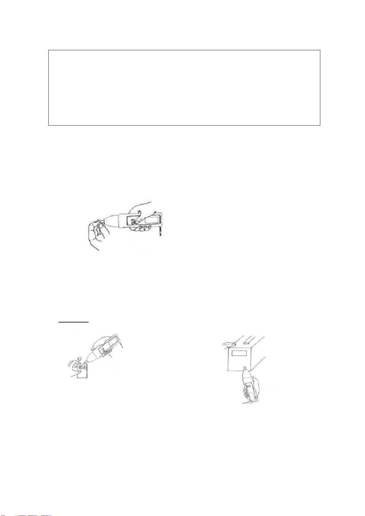
③Discharge the electrostatic capacity of the meter.
Touch to the sensing tip by the fingers of the left hand and hold the unit body by right
hand and press the reset switch as following figure:
Hold the unit body with right hand
When “000” is displayed, release the reset switch.
④Hold the unit body and contact the sensing tip firmly to the conductor or object under
test and read the displayed value.
⑤If you make measurements in a dark place or in a place where it is difficult to see the
readings, use the data hold switch. After measurement, turn the power switch to OFF.
The power is automatically turned to OFF, 10 minutes after the power switch ON.
Examples:
Battery Voltage DC Power Supply
Battery
Display appears
Display will appear by the contrary way
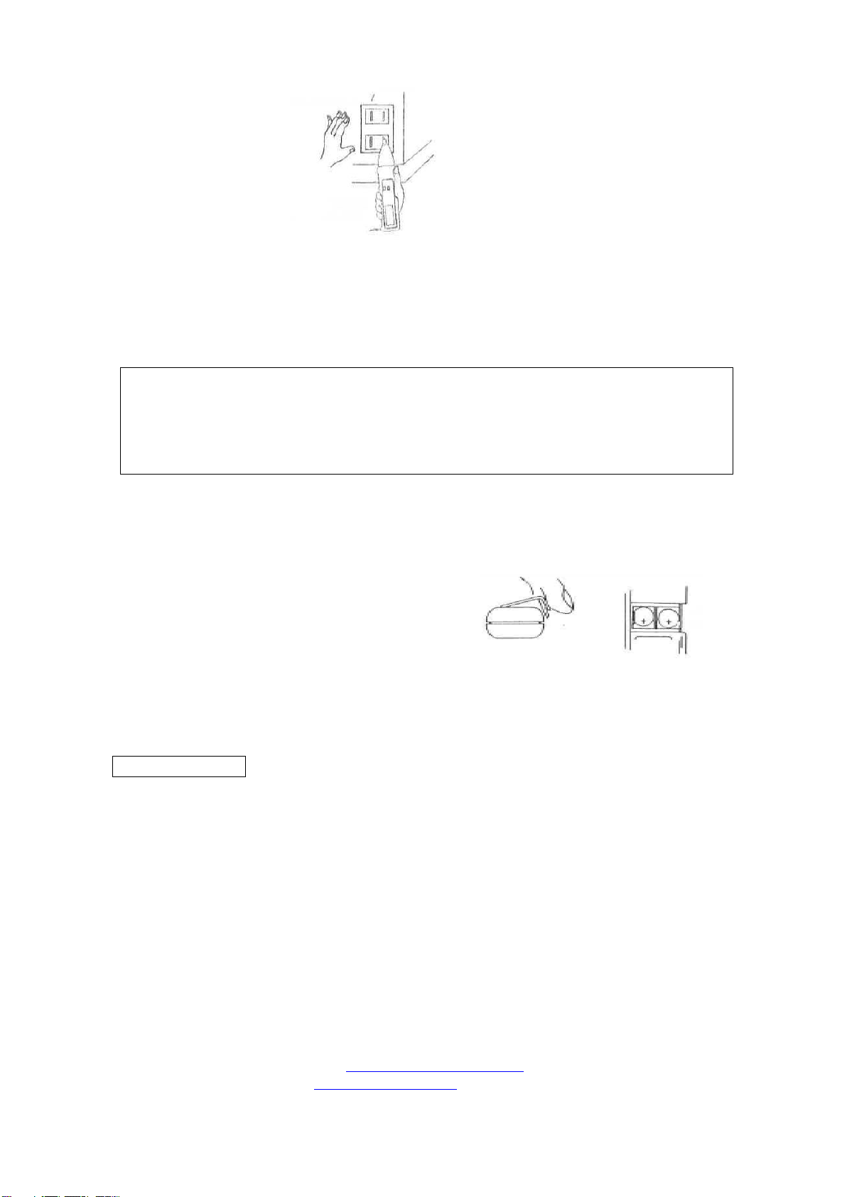
ACV Measurement
①Press the power switch to ON.
②Set the range switch toACV range.
③Discharge the electrostatic capacity of the meter.
④Hold the unit body and contact the sensing tip firmly to the conductor or object under
test and read the displayed value.
If you cannot get the stable reading, touch to the floor or wall with left hand.
(Touch the flame
with left hand)