MULTILANE AT4039EML User manual

AT4039EML |User Manual
[i]
COMMUNICATIONTEST & MEASUREMENTSOLUTIONS
Copyright© MultiLane SAL. All rights reserved.Licensed software productsare ownedby
MultiLane SAL or its suppliers and are protected by United States copyright laws and
international treatyprovisions.
Use, duplication, or disclosure by the Governmentis subjectto restrictions as set forth in
subparagraph (c)(1)(ii) of the Rights in Technical Data and Computer Software clause at
DFARS 252.227-7013, or subparagraphs (c)(1) and (2) of the Commercial Computer
Software -- Restricted Rights clause at FAR 52.227-19, as applicable.
MultiLane SAL products are covered by U.S. and foreign patents, issued and pending.
Information in this publication supersedes that in all previously published material.
Specifications andprice change privilegesreserved.
MultiLane, S.A.L., Houmal Technology Park, Houmal, Mount Lebanon.
AT4039EML software, hardware and documentations are registered trademarks of
MultiLane, S.A.L.

AT4039EML |User Manual
[ii]
COMMUNICATIONTEST & MEASUREMENTSOLUTIONS
Contents
General Safety Precautions......................................................................................1
Preface....................................................................................................................2
Contact MultiLane SAL.............................................................................................3
Product Description.................................................................................................4
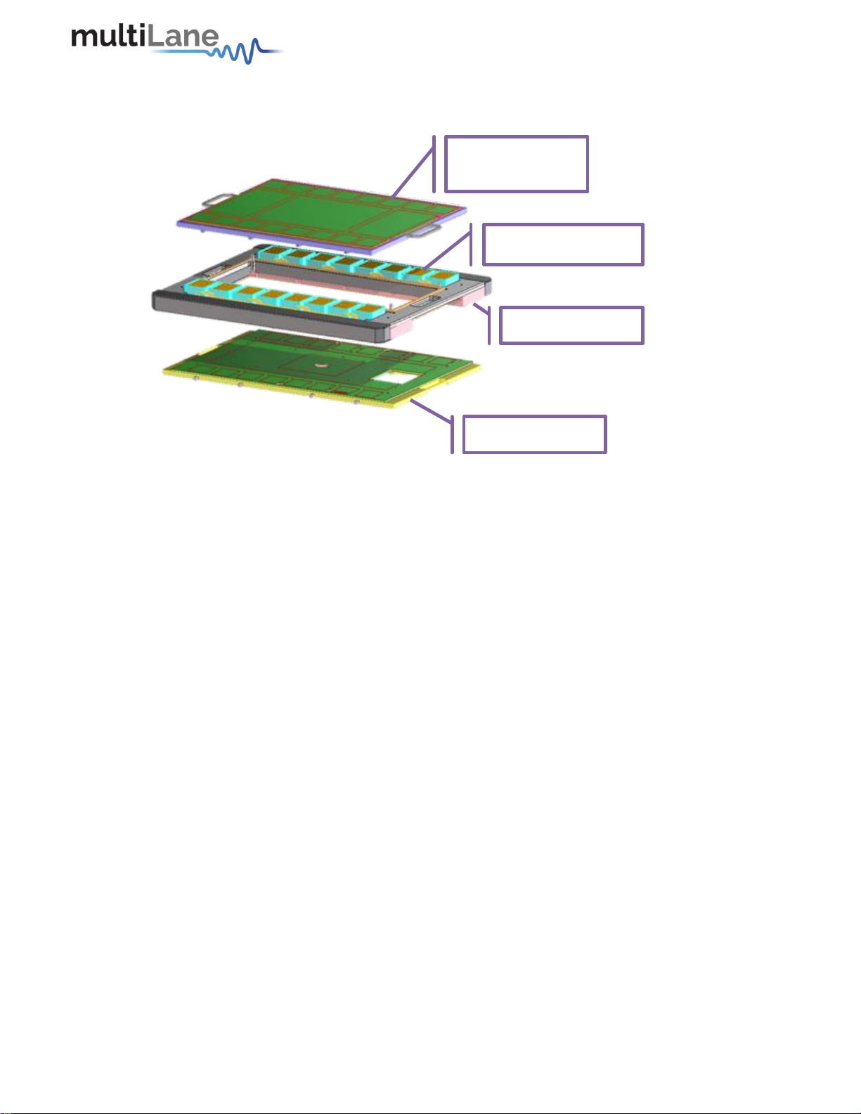
Overview of the Advantest V93000 HSIO Test System...............................................4
Overview.................................................................................................................9
Key Features............................................................................................................9
Target Applications..................................................................................................9
Product Software...................................................................................................10
Minimum PC Requirements.....................................................................11
Installation.............................................................................................................12
First Steps ...............................................................................................12
GUI Overview.........................................................................................................13
Instrument Connect Field......................................................................... 14
PLL Lock and Temperature Status Field .................................................... 14
Reading the installed Firmware Revision..................................................14
Line Rate Configuration (Applies to all channels at once) .......................... 14
Mode & Clock Out Settings (Apply to all channels at once) .......................15
Per-Channel Settings ...............................................................................16
Taking Measurements............................................................................................20
Bit Error Ratio Reading.............................................................................20
BER Control .............................................................................................21
BER Tabe of Results.................................................................................21
BER Graph ...............................................................................................21
Histogram Analysis..................................................................................22
Signal to Noise Ratio Analysis...................................................................23
Log file System........................................................................................23
Saving and Loading Settings..................................................................... 24
How to Connect to the Instrument.........................................................................25
How to Change IP Address and Update Firmware...................................................25
IP Address Changing on AT4039EML ........................................................25
Using Ethernet cable:...........................................................................25
Using USB cable:..................................................................................26
Firmware Upgrade on AT4039EML.........................................................................27 Using Ethernet cable:...........................................................................27
Using USB cable:..................................................................................27
USB Driver Installation......................................................................... 28

AT4039EML |User Manual
[iii]
COMMUNICATIONTEST & MEASUREMENTSOLUTIONS
List of Figures
Figure 1: V93000 CTH....................................................................................................4
Figure 2: The building blocks of the test head extender..................................................5
Figure 3: V93K frame with 4 Multilane cassettesinstalled..............................................6
Figure 4: Components of the Multilane sub-system inside the V93K frame.....................6
Figure 5: Signal path of the ATE system .........................................................................7
Figure 7: AT4039EML BERT GUI ................................................................................... 10
Figure 8: Connect Via Ethernet.................................................................................... 12
Figure 9: Ethernet Configuration ................................................................................. 13
Figure 10: AT4039EML GUI..........................................................................................13
Figure 11: Default Inner and Outer settings of 1000 and 2000 ......................................20
Figure 12: Outer Eye is set 1600; Inner eye kept at 2000 .............................................. 20
Figure 13: BER Control panel....................................................................................... 21
Figure 14: BER Graphs................................................................................................. 22
Figure 15: PAM Histogram .......................................................................................... 22
Figure 16: NRZ Histogram............................................................................................ 23
Figure 17: SNR ratio for PAMsignal ............................................................................. 23
Figure 18: IP Address Changing Using Ethernet Cable................................................... 26
Figure 19: IP Address Changing Using USB Cable ..........................................................26
Figure 20: Firmware Update Using Ethernet Cable....................................................... 27
Figure 21: Firmware Upgrade Using USB Cable ............................................................28
Figure 22: Scan for Hardware Changes ........................................................................ 28
Figure 23: Scanning for Plugs....................................................................................... 29

AT4039EML |User Manual
1|P a g e
COMMUNICATIONTEST & MEASUREMENTSOLUTIONS
General Safety Precautions
Reviewthe followingsafety precautionsto avoid injury and prevent damage to this
product or any products connected to it.To avoid potential hazards, use this product
only as specified.
Only qualified personnel shouldperformservice procedures.
While usingthis product, you may need to access otherparts of the system.Read the
General Safety Summary in other system manuals for warnings and cautions relatedto
operatingthe system.
To Avoid Fire or Personal Injury
Use Proper Power Cord. Only use the power cord specifiedforthis product and certified
for the country of use.
Observe All Terminal Ratings. To avoid fire or shock hazard, observe all ratings and
markings on the product. Consult the product manual for further ratings information
before making connections to the product.
Do not apply a potential toany terminal, includingthe common terminal thatexceeds the
maximum rating of that terminal.
Do Not Operate Without Covers.
Do not operate this product with covers or panels removed.
Avoid Exposed Circuitry. Do not touch exposed connections and components when
power is present.
Do Not Operate with Suspected Failures.
If you suspect there is damage to this product, have it inspected by qualified service
personnel.
Do Not Operate in Wet/Damp Conditions.
Do Not Operate in an Explosive Atmosphere.
Keep Product Surfaces Clean and Dry.
Symbols and Terms in this manual. These terms may appear in this manual:
CAUTION: Caution statements identify conditions or practices that could
result in damage to this product or other property.
CAUTION: Provide adequate cooling. Provide adequatecooling to the board to
avoid damaging any part of it, especially the ATE version of the
board. Refer to the powersection to know the powerdissipation values

AT4039EML |User Manual
2|P a g e
COMMUNICATIONTEST & MEASUREMENTSOLUTIONS
Preface
This isthe useroperation manual for the AT4039EML. It covers the following information:
Describes the capabilities of the instrument: how to install it and its software
packages
Explains how to operate the instrument for: Pattern Generation, Error Detection;
how to control the clocking system, inputs/outputs and all the available
measurements
Calibration procedure
Lists the specifications

AT4039EML |User Manual
3|P a g e
COMMUNICATIONTEST & MEASUREMENTSOLUTIONS
Contact MultiLane SAL
ultiLaneSAL is an engineering services company and an OEM supplier of
specialty test and communication equipment for thesemiconductor and optical
transport industries. Multilane delivers ultra-compact test instruments of the
highest value and performance for high speed communication and signal integrity
applications. The Company has a large engineering team and a fully equipped lab with
state of the art equipment, having recently moved to a 6000sq foot facility in Houmal
Technology Park (HTP).
Multilane SAL customers can leverage great flexibility and capability in product
customization thanks to our team in depth expertise in high speed I/O, Signal Integrity,
and access advanced development and test tools. MultiLane has the resources and know-
how to meet customer’s product development and design requirements. Our R&D has a
proven track record in delivering leading edge products and development tool kits to the
Automated Test market while applying the production processes to deliver high quality
products on schedule and within budget.
Multilane’s team is composed of experienced and disciplined engineers offering products
and turnkey solutions of modules and systems for high speed IO, Signal Integrity, SOC
development and optical communication from verbal requirements (Architecture, PRD,
HW/FW/SW design implementation and characterization).
Address
MultiLane SAL
Houmal Technology Park
Askarieh Main Road
Houmal, Lebanon
Web site
www.multilaneinc.com
Sales support
sales@multilaneinc.com
Support
support@multilaneinc.com
If any further help is needed,please contact MultiLane SAL, by sendinggeneral enquiries
to info@multilaneinc.com.
M

AT4039EML |User Manual
4|P a g e
COMMUNICATIONTEST & MEASUREMENTSOLUTIONS
Product Description
This chapter describes your instrument, operating underWindows.
Installation shows you how to configure and install the instrument, as well as how to
install the system software included with the product.
Incoming Inspection provides a procedure for verifying basic operation and
functionality
Accessories and Options lists the instrument options available and the standard and
optional accessoriesfor this product.
Modeland Package Content
This manual supports the instrument ML4039EML, both Benchtop and ATE. The ATE
versioniscalled AT4039EML and is compatible with the AdvantestV93000 HSIOtest head
extenderframe/twinning.
Hardware Packages
AT4039EML: 4 x 28G NRZ/PAM4 and 4 x 56G NRZ/PAM4 Channels BERT, in a cassette.
Reference clock output and input are accessible through the backplanes AT4000 or
AT2000. 12V power and Ethernet are also provided by the backplane. Channels are
numerated from right to left taking as reference the backplane connector, beginning by
TX with TX1, TX2 to TX4, and then by RX with RX1-N, RX1-P to RX4-N, RX4-P.
Overview of the Advantest V93000 HSIO Test System
The AT4039EML and all the Multilane AT range of Gen 1 products is only compatible with
a specifictype of V93000 test head extenderbased on the Advantest frame E8028BF for
CTH and STH test systems.
Figure 1: V93000 CTH

AT4039EML |User Manual
5|P a g e
COMMUNICATIONTEST & MEASUREMENTSOLUTIONS
Figure 2: The buildingblocksofthe test headextender
Family Board
Base Frame
Pogo Segment
DUT Load board

AT4039EML |User Manual
6|P a g e
COMMUNICATIONTEST & MEASUREMENTSOLUTIONS
Figure 3: V93K framewith 4 Multilane cassettes installed
Figure 4: Components of theMultilanesub-systeminside theV93Kframe

AT4039EML |User Manual
7|P a g e
COMMUNICATIONTEST & MEASUREMENTSOLUTIONS
Item
Description
1
Cassette
Each cassette contains up to 2 instruments. In the shownpicture, the
cassette is holding one AT4039E BERT and one AT4025 DSO
2
Backplane
The backplane providespower,Ethernetand clock to the instruments.
Each AT4000L backplane can support up to 4 instruments
simultaneously
3
Board to board
connector
This 52-pin connector is the interfacefor Ethernet, powerand clocks
between backplane and instrument. These connectors are labeled
U450, U451, U452 and U453
4
Power
connector
Each backplane has a 12V, 13A powerconnector
5
Clock out
Clock out from a BERT is available as a differential pairat the indicated
SMP
6
Clock In
Differential clockinputfor the slave instruments
7
Ethernet
Every backplane has an Ethernet switch builtin. This switch
communicates with your network through the RJ45 labeledJ1.
Communicationto the instruments is handled internallyby the switch
using backplane traces.
Table 1: AT4039EMLports
The main advantage of the ATE system as compared to using benchtop instruments, is
that the signal path is considerably shorterthus reducing insertion and return losses;the
Figure 5: Signal path of the ATEsystem

AT4039EML |User Manual
8|P a g e
COMMUNICATIONTEST & MEASUREMENTSOLUTIONS
channel density is up to 32 on the Gen 1 system, and the mating of the channels is
simultaneous in one move. Alsothe bandwidth of the coaxial assemblyis 50+ GHz.
All APIs are available for Linux and tested under SmarTest 7. For the listof APIs and how
to use them, please consult the programmer’s guide. The remainder of this guide only
explainsthe Windows GUI and how it isused to set up measurements.

AT4039EML |User Manual
9|P a g e
COMMUNICATIONTEST & MEASUREMENTSOLUTIONS
User Guide
Manual containing user operation guide, software installation and start up procedure,
using the ML BERT Windows GUI.
This manual does not explain how to operate the instrument using SmarTest
environment.
Software package and documentations:
Main ML4039EML/AT4039EML Windows GUI.
USB driver.
Overview
AT4039EML is a low cost, simple to use, fully integrated, ultra-compact, USB/Fast
Ethernet controlled instrument that combines the functions and features of a signal
generator, bit error-rate tester and data analysis system with Post Emphasis and Pre
Emphasis capabilities.
Key Features
Data Rates 23 –29 and 46 - 58 GBd
Low power consumption < 22 W
API libraries
LabView driverand Python wrapper available
Target Applications
Production testingof transceivers
Functional and SI testing

AT4039EML |User Manual
10|P a g e
COMMUNICATIONTEST & MEASUREMENTSOLUTIONS
Product Software
Figure 6: AT4039EMLBERTGUI
The instrumentincludesthe followingsoftware:
AT4039EML GUI.
MultiLane AT4039EML USB driver.
ML IPChanger
InstrumentGUI runs on Windows XP (32/64 bit), Windows7,8 and 10.
NOTE. These applications require the Microsoft .NET Framework 3.5.
If the Microsoft.NET Framework 3.5 is needed, it can be downloaded through this link:
http://download.microsoft.com/download/2/0/e/20e90413-712f-438c-988e-
fdaa79a8ac3d/dotnetfx35.exe.
For more products updates,check the followingwebpage:
www.multilaneinc.com/products.html

AT4039EML |User Manual
11|P a g e
COMMUNICATIONTEST & MEASUREMENTSOLUTIONS
Minimum PC Requirements
The Windows PC requirements for the AT4039EML GUI application should meet the
followingspecifications:
Windows 7 or greater
Minimum 1 GB RAM
1 Ethernet card to establishconnection withthe device
USB Connector
Pentium4 processor 2.0 GHz or greater
.NET Framework 3.5 sp1
NOTE. It is recommended to connect the BERT via Ethernet to one PC only to prevent
conflict from multiple user commands.
NOTE. It is not recommended to hook up the instrument to a slow network or to connect
to it through WiFi

AT4039EML |User Manual
12|P a g e
COMMUNICATIONTEST & MEASUREMENTSOLUTIONS
Installation
This chapter covers installation of the instrument, addressingthe followingtopics:
SystemStart-up
How to connect to the instrument
First Steps
When youfirstreceive the instrument, it has a pre-configuredIP address from the
factory. This IP addressis printed ona label on the instrument. You may choose to
keepthisIP or to change it. If you needto change the IP, there are twoways to do
so: either through the USB interface, or through the Ethernet interface.If you do
choose USB, then you first have to install the USB driver of this instrument from
the ML website, then use the application named ETHconfig. If howeveryou choose
the LAN interface to change the IP, then you need to download the application
IPChanger from the ML website then temporarily change your PC’s IP to be in the
same domain as the instrument, i.e. 172.16.xx.xx. once you’ve successfully
changed the instrument’s IP, you can change back your PC’s IP.
Please make sure you print a label withthe newly assignedIP address and stick it
on the instrument. If for some reason you cannot rememberwhatIP address your
instrumenthas, you will have touse the USBinterface togetherwiththe ETHconfig
software to “read” the IP.
Connect through Ethernet:
Connect the PC to the front panel via the RJ45 connector located on the front
panel through an Ethernet cable to be able to control it.
In order to connect via Ethernet, the IP address of the board is required.
To learn more options on how to connect the Ethernet cable go to the section
Connect through an EthernetCable.
oNote that no drivers are required; you simply should know the current
board IP address, you need to enter it in the text box next to the IP label
shown in the below picture, then click on the connect button.
Figure 7: ConnectViaEthernet
oYou are now connected.
oOnce connected, the Connect button turns into Disconnect.
oTo make sure that you are connected, you can also ping your device.
oTo change the IP address of the board, you need to install the USB drivers
(referto section USB DriverInstallation).
oInstall the Ethernet configuration software that allows you to read, write
the IP address, Mask and Gateway of the instrument.

AT4039EML |User Manual
13|P a g e
COMMUNICATIONTEST & MEASUREMENTSOLUTIONS
Figure 8: EthernetConfiguration
The instrumentis now poweredupand connectedthrough the right IP address. Next,you
need to configure the signal generated.
GUI Overview
Figure 9: AT4039EMLGUI
In your instrument’s GUI, there are several control fields that are each explained below.

AT4039EML |User Manual
14|P a g e
COMMUNICATIONTEST & MEASUREMENTSOLUTIONS
Instrument Connect Field
The first thingyou want to do is to make sure you are connected to the instrument. If
you are, the connect button will read Disconnectand the green LED lights up.
PLL Lock and Temperature Status Field
Keepan eye on the LEDs and temperature readings on this field. TX Lock meansthat the
PLL of the PPG is locked. RX lock goes green only if a signal of correct polarity and PRBS
kindis detected on the error-detector.
If the temperature reaches 65C, the electronicswill auto shut off.
Reading the installed Firmware Revision
The installedfirmware versionis displayed inthe upperright corner of the GUI.
Line Rate Configuration (Applies to allchannels at once)
This is where you set the bitrate for all 4 channels. You can also selectthe clockinput.The
clock is internal by default. You should only change to external clock feed in when you
need to synchronize two or more AT4039EMLs to each other in a slave-masterfashion;In
that case you connect the clocks in daisy chain. After changing from internal to external

AT4039EML |User Manual
15|P a g e
COMMUNICATIONTEST & MEASUREMENTSOLUTIONS
clock and vice versa, you have to click apply for changes to take effect (this takes a few
seconds).
Mode & Clock Out Settings (Apply to all channels at once)
The “Ref” denotes the frequency of
the clock output. This is a function of
the bitrate and will vary according to
your clock-out settings under the
“Mode” menu. Knowing the clock
frequency being output by the BERT is
helpful when you want to trigger an
oscilloscope.
Some oscilloscopes require a clock
frequency above 2 GHz. To get the
AT4039EML to output that, go under
mode settings and select the Clock out
to be “Monitor”. Choose the
denominator so that the result is
within the scope range.
To switch betweenNRZ and PAM-4
coding, use the TX Mode setting, then
click Apply.
The options Gray Mapping and DFE
pre-coding are only available in PAM4
mode.
DFE Pre-coding sends a pre-amble for a
DFE receiver to sync to before the
actual PRBS pattern is transmitted, to
avoid DFE error propagation. The
decoder implements a 1+D scheme in
response to an 𝒙 = 𝟏
𝟏+𝐃
encoding.
Currently the DFE precoding is
automatic and not user-selectable.
Gray Mapping enablesuse of PRBSxxQ
definedin IEEE802.3bs. When Gray

AT4039EML |User Manual
16|P a g e
COMMUNICATIONTEST & MEASUREMENTSOLUTIONS
mapping is enabled, the PRBS13 and
PRBS31 under the pattern select menu
turn into PRBS13Q and PRBS31Q
respectively.Gray mapping basically
re-arranges the symbol mapping to the
following:
00 0
01 1
11 2
10 3
Per-ChannelSettings
You can adjust these settingson a per channel basis. These are:
The AT4039EML can
output a wide range of
pre-defined patterns. In
addition to the PRBS
patterns, there are
linearity and jitter test
patterns. Also, on top of
the pre-definedpatterns
the user has the
possibility of defining
his/her own pattern –
more on this further
below.
Note: error detection
only works on the PRBS
patterns existing in the
RX pattern drop down
list. It isn’t possible to do
Table of contents
Other MULTILANE Test Equipment manuals