Return Loss ......................................................................................................................................... 23
Advanced Settings .......................................................................................................................... 23
Calibration....................................................................................................................................... 23
SOLT ............................................................................................................................................ 23
Gating.......................................................................................................................................... 24
Return Loss Measurement.............................................................................................................. 25
Table of Figures:
Figure 1: ML4035 GUI Main Page ............................................................................................................... 10
Figure 2: ML4035 Front View ..................................................................................................................... 11
Figure 3: ML4035 connected to PC via Ethernet........................................................................................ 12
Figure 4: ML4035 connected to PC Wirelessly ........................................................................................... 12
Figure 5: ML4035 with USB connection ..................................................................................................... 13
Figure 6: Connect Via Ethernet................................................................................................................... 14
Figure 7: Ethernet Configuration................................................................................................................ 15
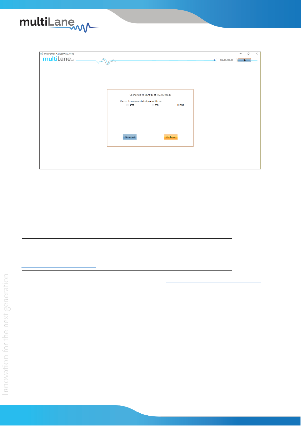
Figure 8: Mode Selection............................................................................................................................ 16
Figure 9: Calibration.................................................................................................................................... 16
Figure 10: Add TDR Channels...................................................................................................................... 17
Figure 11: Cable Matching.......................................................................................................................... 18
Figure 12: TDR Measurement..................................................................................................................... 18
Figure 13: Velocity of Propagation ............................................................................................................. 19
Figure 14: Advanced Options...................................................................................................................... 19
Figure 15: Adding TX/RX Channels & Calibration ....................................................................................... 20
Figure 16: S21 Calibration Wizard .............................................................................................................. 21
Figure 17: S21 Calibration Plot ................................................................................................................... 21
Figure 18: S21 Measurement ..................................................................................................................... 22
Figure 19: IL Measurements ....................................................................................................................... 22
Figure 20: ILD & IL Fitted ............................................................................................................................ 22
Figure 21: De-Embedding ........................................................................................................................... 23
Figure 22: S11 Advanced Options............................................................................................................... 23
Figure 23: SOLT Calibration......................................................................................................................... 24
Figure 24: Calibration Wizard (Gating) ....................................................................................................... 24
Figure 25: Applying Markers....................................................................................................................... 25
Figure 26: Return Loss Measurement ........................................................................................................ 26
Figure 27: S11 Measurements.................................................................................................................... 26
Figure 28: Return Loss Mask....................................................................................................................... 26