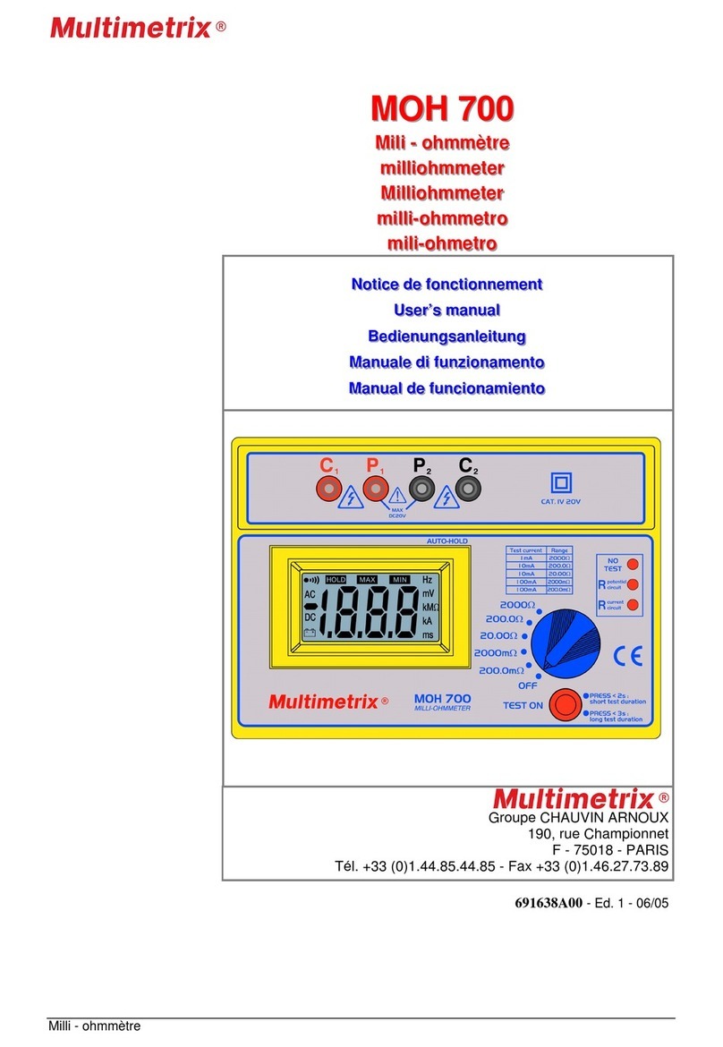
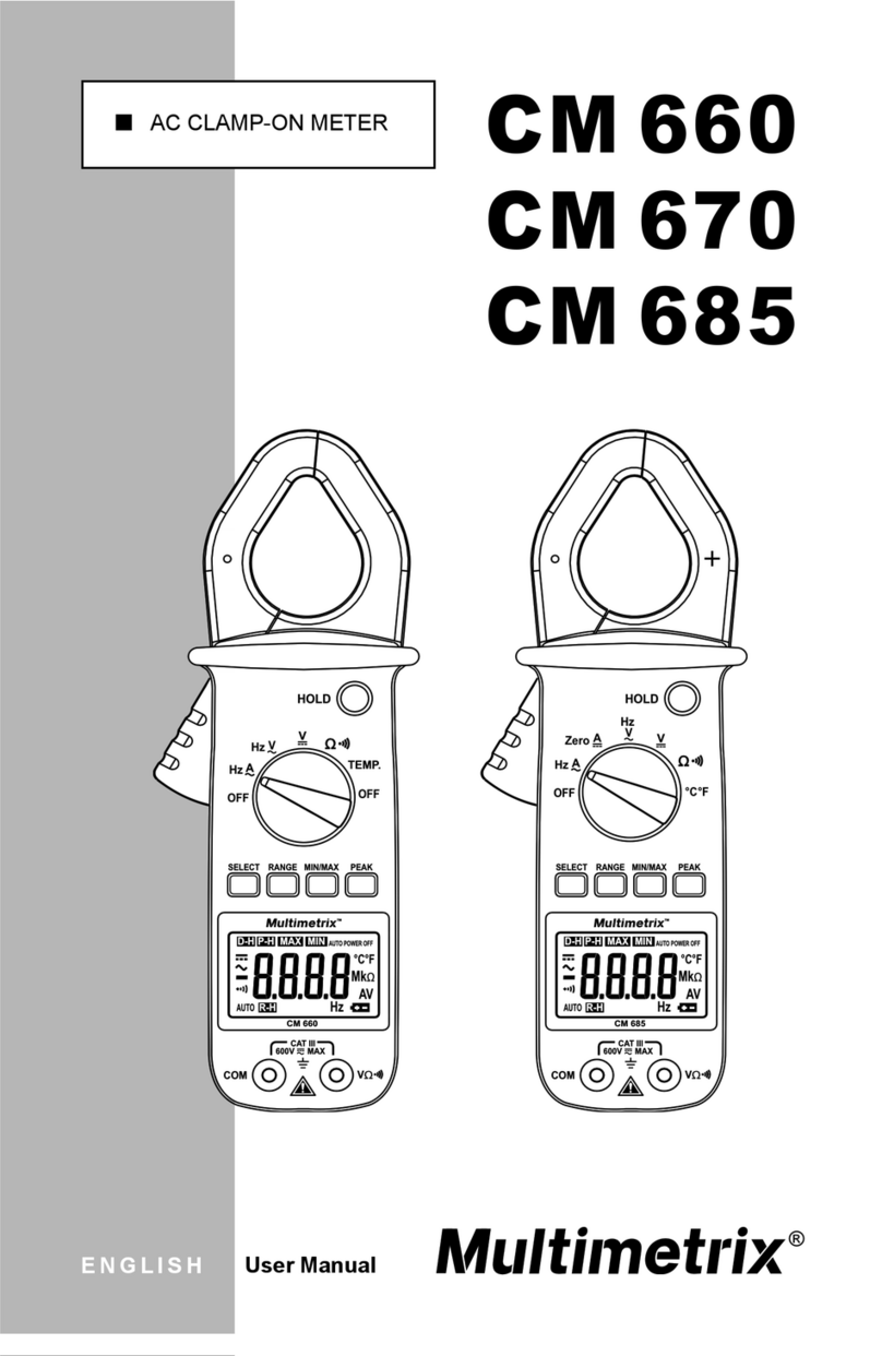
Multimetrix CM600 User manual

FRANÇAIS
ENGLISH
DEUTSCH
ITALIANO
ESPANOL
CM600
CM610
CM625
Notice de fonctionnement
User’s manual
Bedienungsanleitung
Libretto d’istruzioni
Manualdeinstrucciones
PINCE AMPEREMETRIQUE
DIGITAL CLAMP METER
MULTIMETER MESSZANGE
MULTIMETRO
MULTIMERICA

1
Français ....................................................................................2
English ....................................................................................10
Deutsch...................................................................................18
Italiano.....................................................................................26
Español................................................................................... 34
691178A00
A00

2
CONDITIONS GENERALES
DE GARANTIE ET DESECURITE
1. PRECAUTIONS D’EMPLOI
Lisez les instructions de sécurité ci-dessous avant toute
utilisation de l’appareil, afin d’éviter les accidents corporels,
tels que brûlures et chocs électriques.
Suivez impérativement les indications précédées du
symbole
1.1 DEFINITION DES CATEGORIES D’INSTALLATION
(cf. CEI 664-1)
CAT I : Circuits protégés par des dispositifs limitant les
surtensions transitoires à un faible niveau.
Exemple : circuits électroniques protégés.
CAT II : Circuits d'alimentation d'appareils domestiques ou
analogues, pouvant comporter des surtensions transitoires
de valeur moyenne.
Exemple : alimentation d'appareils ménagers et d'outillage
portable
CAT III : Circuits d'alimentation d'appareils de puissance
pouvant comporter des surtensions transitoires importantes.
Exemple : alimentation de machines ou appareils industriels
1.2 NORME
Se référer aux normes et catégories d’installation
mentionnées dans la notice spécifique de l’appareil.
Attention : cet appareil n’est pas un Vérificateur d’Absence
de tension, ni un détecteur de Tension au sens de l’UTE
C18510.
1.3 EXPLICATION DES SYMBOLES
Symbole
Signification
Symbole
Signification
Instrument à
double isolation
Fusible
Courant alternatif
Homologation CE
Courant continu
Conformément à la
directive WEEE
2002/96/EC
Attention : se
référer aux
instructions
d’utilisation
Ne pas appliquer
ou enlever sur des
conducteurs sous
tension
dangereuse.
Terre
1.4 POUR TRAVAILLER EN SECURITE
Ce pictogramme est applicable à tout le paragraphe.
Soyez particulièrement vigilants pour des tensions
supérieures à 30 VAC RMS et 50 VDC.
Ne travaillez jamais au-delà des plages de tension
maximales indiquées notamment par rapport à la terre.
Lors de la mesure d’intensité, vérifiez toujours que la valeur
du courant à mesurer est compatible avec le calibre de
l’appareil. Pour les appareils équipés de fusibles, contrôler
leur état avant toute mesure. Remplacez les fusibles usagés
par ceux recommandés dans la notice spécifique au produit.
N’utilisez pas l’appareil dans un environnement humide et/ou
poussiéreux.
N’utilisez jamais l’appareil sans gants pour électriciens et
autres équipements de sécurité préconisés par la législation.

3
Les doigts ne doivent jamais dépasser la garde de la pointe
de touche.
Ne mettrez jamais les doigts en contact avec la partie
métallique de la pointe de touche.
Vérifiez la qualité mécanique et électrique des cordons et
des pointes de touche avant toute mesure. Les pointes de
touche ou cordons endommagés devront être
immédiatement changés. N’utilisez pas l’appareil en cas de
détérioration.
Ne travaillez jamais avec le boîtier arrière de l’instrument
ouvert.
Ne changez pas les piles lorsque les cordons sont
connectés.
N’utilisez pas ou n’exposez pas l’instrument au soleil, à des
températures ou un taux d’humidité élevés.
Ne modifiez jamais le circuit électronique interne.
Ne démontez pas le boîtier ; seule la trappe à piles peut être
ouverte.
Ne modifiez jamais le circuit électronique interne.
1.5 RECOMMANDATIONS DIVERSES DE SECURITE
Pour les appareils des catégories d’installation I et II, ne
travaillez jamais sur des équipements pouvant générer des
pics de tension (moteurs, etc.).
Pour la mesure en gamme manuelle, commencez toujours
par la gamme maximale. Sélectionnez ensuite la gamme la
plus appropriée.
Connectez en premier la pointe de touche noire, puis la
rouge.
Déconnectez les cordons préalablement au changement de
fonction.
Déconnectez en premier la pointe de touche rouge, puis la
noire.
Utilisez et installez les piles conformément aux instructions
de la notice spécifique au produit acheté.
Vérifiez l’absence de tension avant l’utilisation des fonctions
ou Ω.
2. GARANTIE
Ce matériel est garanti contre tout défaut de matière ou vice de
fabrication, conformément aux conditions générales de vente.
Durant la période de garantie, l'appareil ne peut être réparé que
par le constructeur, celui-ci se réservant la décision de
procéder soit à la réparation, soit à l'échange de tout ou partie
de l'appareil. En cas de retour du matériel au constructeur, le
transport allé est à la charge du client. La garantie ne
s’applique pas suite à :
Une utilisation impropre du matériel ou par association de
celui-ci avec un équipement incompatible.
Une modification du matériel sans autorisation explicite des
services techniques du constructeur.
L’intervention effectuée par une personne non agréée par le
constructeur.
L’adaptation à une application particulière, non prévue par la
définition du matériel ou par la notice de fonctionnement.
Un choc, une chute ou une inondation.
Renseignements et coordonnées de nos services après-vente :
En France Métropolitaine, sur demande au 02.31.64.51.55.
ou auprès de votre distributeur.
3. DEBALLAGE ET RE-EMBALLAGE
L’ensemble du matériel a été vérifié mécaniquement et
électrique-ment avant l’expédition.

4
Toutefois, il est conseillé de procéder à une vérification rapide
pour détecter toute détérioration éventuelle lors du transport. Si
tel était le cas, faites alors immédiatement les réserves d’usage
auprès du transporteur.
En cas de réexpédition, utilisez l’emballage d’origine et
indiquez, par une note jointe à l’appareil, les motifs du renvoi.
4. MAINTENANCE
4.1 VERIFICATIONS METROLOGIQUES
Comme tous les appareils de mesure ou d'essais, une
vérification périodique est nécessaire.
Renseignements et coordonnées sur demande :
tél. 02.31.64.51.55 - fax 02.31.64.51.09 ou auprès de votre
distributeur.
4.2 ENTRETIEN
Périodiquement, nettoyez votre multimètre avec un tissu
humide imprégné d'eau savonneuse. N’utilisez pas de matières
abrasives ou contenant des solvants.
4.3 REPARATION HORS DE FRANCE METROPOLITAINE.
Pour toute intervention sous garantie ou hors garantie,
l’appareil sera retourné au distributeur.
5. STOCKAGE
Retirez les piles et stockez-les séparément, si votre appareil de
mesure de devait pas être utilisé pendant une période > 60
jours.
UTILISATION
6. PRESENTATION
6.1 LA FACE AVANT
Repère
Fonction
1.
Borne négative noire (-) COM
2.
Afficheur à cristaux liquides :
- CM600 / CM610 : 3 digits ½ (1999 points)
- CM625 : 4 digits (4369 points)
‘----‘ : dépassement de capacité en mesure de
courant et tension
3.
Sélecteur rotatif de fonction
OFF : multimètre hors-tension
: courants alternatifs (CM600 / CM610 : 600 A
et CM625 : 400 A)
: courants continus
(uniquement CM625 : 400 A).
: tensions alternatives CM600 / CM610
et CM625 (600 V).
: tensions continues CM600 / CM610
et CM625 (600 V).
: résistance (uniquement CM600 / CM610 :
20MΩ).
: résistance et de continuité
(uniquement CM625 : 40 MΩ).
: test de diode et de continuité
(uniquement CM600 / CM610).

5
4.
Poignée d’ouverture de la pince
5.
La main doit toujours se trouver à l’arrière de cette
protection durant la mesure.
7.
Le conducteur doit être localisé au centre de cette
zone durant la mesure pour une précision
maximale.
8.
Touche MAX (CM600 et CM610 ) : pour les
fonctions affiche la valeur maximale
mesurée ; cette dernière est automatiquement mise
à jour. L’icône est affichée lorsque la fonction
est activée ; un nouvel appui annule la fonction.
9.
Touche SELECT :
CM600 et CM610 : sélectionne alternativement le
test de diode ou de continuité
CM625 : sélectionne alternativement la mesure de :
- courant continu ou de remise à zéro (gamme 40
ADC)
- résistance ou de test de continuité
10.
Borne positive rouge (+)
11.
CM625 : indication de l’orientation de la pince
12.
Touche HOLD (CM625 ): fige la mesure (Data Hold)
; l’icône est affichée lorsque la fonction est
activée. Un nouvel appui annule la fonction. Dans
ce mode, la mise à l’arrêt automatique AUTO
POWER OFF (rep. 25) est désactivée.
6.2 L’AFFICHEUR
Repère
Fonction
Repère
Fonction
13.
Continuité
20.
Résistance
14.
Valeur négative
21.
Tension courant
15.
Alternatif
22.
Valeur maximale
16.
Continu
23.
Gammes auto
17.
Piles faibles
24.
Maintien valeur
18.
Valeur max.
25.
Arrêt auto
19.
Test de diode
CM625 uniquement
6.3 LA FACE ARRIERE
Repère
Fonction
Repère
Fonction
27.
Texte de sécurité
28.
Logement piles
7. UTILISATION
7.1 MISE EN SERVICE DE LA PINCE MULTIMETRE
Positionner le sélecteur (rep. 3) sur une position autre que OFF.
7.2 ARRET DE LA PINCE MULTIMETRE
Arrêt manuel
Positionner le sélecteur (rep. 3) sur OFF.
Arrêt automatique
Le multimètre s’éteint automatiquement (CM600 et CM610 : 15
mn, CM625 : 10 mn) après la dernière mesure ; le buzzer émet
un signal sonore une minute avant l’arrêt. L’appui sur une
touche, excepté SELECT, relance le multimètre.
Annuler l’arrêt automatique (CM625 uniquement)
1. Positionner le sélecteur (rep. 3) sur OFF.
2. Maintenir la touche HOLD appuyée et tourner le
sélecteur (rep. 3) sur une position autre que OFF.
L’icône AUTO POWER OFF s’efface ; l’arrêt automatique
est désactivé.
Relancer l’arrêt automatique (CM625 uniquement)
1. Positionner le sélecteur (rep. 3) sur OFF.
2. Positionner le sélecteur (rep. 3) sur une position autre que
OFF.

6
L’icône AUTO POWER OFF s’affiche ; l’arrêt automatique
est activé.
7.3 MESURE DE TENSION
Lisez les recommandations de sécurité avant utilisation.
Gammes de mesure automatiques :
- CM600 et CM610: 200 mVDC à 600 VDC (5 gammes) et
2 VAC à 600 VAC (4 gammes).
- CM625 : 4 VDC à 600 VDC (4 gammes) et 4 VAC à 600
VAC (4 gammes).
1. Positionner le sélecteur (rep. 3) sur le symbole
tension.
2. Insérer le connecteur noir dans la borne COM (rep. 1),
le rouge dans la borne + (rep. 10) et lire la valeur de la
tension une fois celle-ci stabilisée.
Lorsque l’icône AUTO (rep. 23) est affichée, le multimètre
détermine la gamme de mesure optimale.
L’affichage de « ----- » indique un dépassement de
capacité.
- CM600 et CM610 pour afficher la valeur maximale, voir §.
7.9.
- CM625 : pour mémoriser la valeur lue, voir §. 7.10.
3. Positionner le sélecteur sur OFF.
7.4 MESURE DE COURANT CONTINU (CM625)
Lisez les recommandations de sécurité avant utilisation.
Gammes de mesure automatiques :
- CM625 : 40 ADC ou 400 ADC (2 gammes)
1. Positionner le commutateur (rep. 3) sur Zero .
2. Appuyer sur la touche SELECT (rep. 9) pour régler le
zéro.
Le réglage du zéro n’est actif que sur la gamme 40 A.
3. Appuyer sur la poignée (rep. 4) pour ouvrir la pince
(rep. 6) et placer un conducteur au centre de la pince
(Fig. 4).
NB : ne jamais insérer les deux conducteurs +et –d’un
même circuit dans la pince ; la lecture serait nulle.
4. Lire la valeur du courant une fois celle-ci stabilisée.
L’affichage de « ----- » indique un dépassement de
capacité.
Pour mémoriser la valeur lue, voir §. 7.10.
5. Ouvrir la pince, libérer le conducteur et positionner le
sélecteur sur OFF.
7.5 MESURE DE COURANT ALTERNATIF
Gammes de mesure automatiques :
- CM600 et CM610 : 200 AAC ou 600 AAC (2 gammes).
- CM625 : 40 AAC ou 400 AAC (2 gammes).
1. Positionner le sélecteur (rep. 3) sur .
Les icônes (rep. 15 et 21) sont affichées.
2. Appuyer sur la poignée (rep. 4) pour ouvrir la pince
(rep. 6) et placer un conducteur au centre (rep. 29).
NB : ne jamais placer les deux conducteurs d’un même
circuit dans la pince ; la lecture serait nulle.
3. Lire la valeur du courant une fois celle-ci stabilisée.
L’affichage de « ----- » indique un dépassement de
capacité.
- CM600 et CM610 : pour afficher les valeurs max., voir
§. 7.9.
- CM600 et CM610 : pour mémoriser la valeur lue, voir §.
7.10.
4. Ouvrir la pince, libérer le conducteur et positionner le
sélecteur sur OFF.

7
7.6 MESURE DE RESISTANCE
Lisez les recommandations de sécurité avant utilisation.
Le circuit sera impérativement hors-tension.
Gammes de mesure automatiques :
- CM600 et CM610 : 200 Ω ou 20 MΩ (6 gammes).
- CM625 : 400 Ω ou 40 MΩ (6 gammes).
1. CM600 et CM610 : positionner le sélecteur (rep. 3)
sur .
CM625 : positionner le sélecteur (rep. 3) sur .
2. Insérer le cordon noir dans la borne COM (rep. 1) et le
cordon rouge dans la borne + (rep. 10) et lire la valeur.
L’affichage de OL indique un dépassement de capacité.
3. Positionner le sélecteur sur OFF.
7.7 TEST DE DIODE (CM600 et CM610)
Lisez les recommandations de sécurité avant utilisation.
Le circuit sera impérativement hors-tension.
1. Positionner le commutateur sur .
2. Procéder à l’essai en direct.
Connecter la pointe noire sur la cathode et la pointe rouge
sur l’anode. La mesure est de 0,5 à 0,7 V pour une diode
au silicium et de 0,2 à 0,3 V pour une diode au
germanium. Une valeur proche de zéro indique un court-
circuit. L’indication OL indique une diode coupée.
3. Procéder à l’essai inverse.
Pointe noire sur l’anode et pointe rouge sur la cathode.
Une diode correcte affiche OL. La diode est défectueuse
si une tension est affichée.
4. Positionner le sélecteur sur OFF.
7.8 TEST DE CONTINUITE
Lisez les recommandations de sécurité avant utilisation.
Le circuit sera impérativement hors-tension.
1. CM600 et CM610 : positionner le sélecteur (rep. 3) sur
et appuyer sur SELECT pour afficher (rep.
13).
CM625 : positionner le sélecteur (rep. 3) sur et
appuyer sur SELECT pour afficher (rep. 13).
2. Insérer le cordon noir dans la borne COM (rep. 1), le
rouge dans la borne + (rep. 10) et appliquer les
pointes de touche sur le circuit à contrôler.
Le signal sonore sera audible lorsque le circuit à contrôler
est continu ou de résistance inférieure à 90 Ω ± 40 Ω
(CM600 et CM610) et 50 Ω ± 25 Ω (CM625).
3. Positionner le sélecteur sur OFF.
7.9 FONCTION MAX (AFFICHAGE VALEUR MAXIMALE -
CM610)
1. Positionner le sélecteur sur ou et
appuyer sur MAX. L’icône est affichée (rep. 18).
2. Effectuer la mesure.
La mesure maximale sera automatiquement mise à jour.
3. Pour désactiver la fonction , appuyer sur MAX.
7.10 FONCTION HOLD (MEMORISATION VALEUR LUE
CM625)
1. Appliquer les pointes de touche sur le circuit à
contrôler.
La mesure maximale sera automatiquement mise à jour.
2. Appuyer sur la touche HOLD durant la mesure.
L’icône (Data Hold) est affichée (rep. 24) ; la mesure
est mémorisée.
La fonction d’arrêt automatique est désactivée.

8
1. Pour désactiver la fonction , appuyer sur
HOLD.
8. REMPLACEMENT DES PILES
Lisez les recommandations de sécurité avant utilisation.
Le circuit sera impérativement hors-tension.
Remplacer les piles lorsque l’icône est affichée (rep. 17) :
1. Déconnecter les pointes de touche.
2. Positionner le commutateur sur OFF.
3. Retirer vis de fixation et couvercle de logement de
piles. Changer les 2 piles 1,5 V (AAA/LR3) en
respectant les polarités.
4. Remonter (couvercle de logement de piles et vis).
NB : retirer les piles en cas d’inutilisation prolongée du
multimètre.

9
9. CARACTERISTIQUES
9.1 GENERALES
Mesure des valeurs
CM600, CM610 & CM625 :
Tensions continues, tensions
alternatives, courant alternatif,
résistance, test de continuité
CM600 et CM610. : test de diodes
CM625 : courant continu
Méthode de
mesures
CM610 & CM625 :True RMS AC
(tension efficace vraie)
Afficheur
CM600 et CM610 : 2000 points
CM625 : 4369 points
Indication de
polarité
Signe « - »
Fonctions
additionnelles
sélectionnables
Sélection de gamme automatique
Arrêt automatique (actif ou non)
Affichage de dépassement de
capacité
CM600 & CM610 : mesure
maximale (MAX)
CM625 : mémorisation de mesure
(Data Hold)
Indication usure
piles
Symbole piles faibles .
Fréquence
d’échantillonnage
CM600 et CM610 : environ 3 x par s
CM625 : environ 2 x par s
Ouverture
maximale des
mâchoires
30 mm
Utilisation
0 à 50°C (32°F - 122°F), RH < 80
%, absence de condensation
Stockage
-10°C à 60°C (14 - 140°F), RH < 70
%, absence de condensation et
batterie retirée
Alimentation
2 piles 1,5 V type LR3 (AAA)
Autonomie
(en mesure VDC)
CM600 et CM610 : 400 h (piles
alcalines) ou 200 h (piles standard)
CM625 : 100 h (piles alcalines)
Dimensions et
masse (avec
batteries)
189 x 71 x 37 mm (L x l x H)
CM600 et CM610 : 200 g
CM625 : 220 g
Degré de pollution
2
Sécurité électrique
EN 61010-1 – EN 61010-2-032 –
EN 61010-2-033
300 V CAT III
Livrés avec
l’instrument
2 piles 1,5 V type AAA/LR3
2 cordons
1 notice de fonctionnement
1 protection
9.2 CONDITIONS DE RÉFÉRENCES
Conditions de références : 18°C - 28°C ; RH < 80 %, absence
de condensation
Voir tableau, page 42.

10
GENERAL SAFETY
AND GUARANTEE CONDITIONS
1. PRECAUTIONS DURING USE
Please read the safety instructions below before using the
instrument to avoid any accidental injuries, such as burns or
electric shocks.
You must observe the instructions preceded by the symbol
.
1.1 DEFINITION OF THE INSTALLATION CATEGORIES
(Cf. CEI 664-1)
CAT I: Circuits protected by devices restricting temporary
excessive voltages to a low level.
E.g.: protected electronic circuits
CAT II: Power circuits for domestic appliances or similar
equipment, which may be subject to medium level temporary
excessive voltages.
E.g.: power supplies for domestic appliances and portable
power tools
CAT III: Power circuits for powerful machinery, which may be
subject to significant temporary excessive voltages.
E.g.: power supplies for industrial machinery and equipment
1.2 NORMS
Please refer to the norms and installation categories
mentioned in the specific instructions for each unit.
1.3 EXPLANATION OF THE SYMBOLS
Symbol
Definition
Symbol
Definition
Instrument with
double insulation
Fuse
Alternating current
(AC)
CE approved
Direct current (DC)
Accordi
ng to WEEE
directive
2002/96/EC
Warning! Please
refer to the operating
instructions.
Do not apply around
or remove from
hazardous live
conductors
Earth
1.4 FOR WORKING SAFELY
This symbol applies to the whole of this section.
Take particular care with voltages in excess of 30 VAC RMS
and 50 VDC.
Never work above the indicated maximum voltage ranges,
particularly as regards the Earth.
When measuring the intensity, always check that the value
for the current to be measured is compatible with the size of
the instrument. For instruments fitted with fuses, check the
fuses’ condition before taking any measurements. Only
replace worn-out fuses with the fuses recommended in the
product’s instruction manual.
Never use the instrument in a damp or dusty environment.
Never use the instrument without wearing electrician’s gloves
and the other safety equipment recommended by the
legislation.
Never move your fingers outside the guard for the contact
points.

11
Never touch any metal part of the contact points with your
finger.
Check the mechanical and electrical condition of the power
cables and the contact points before taking any
measurements. Any power cables or contact points that are
damaged must be replaced immediately. Never use the
instrument if it is damaged.
Never work with the instrument’s rear casing open.
Never change the batteries while the power cables are
connected.
Do not use the instrument in, or expose it to, direct sunlight,
high temperatures or high levels of humidity.
Never alter the internal electronic circuits.
Do not remove the casing; only the battery compartment
cover may be opened.
Never alter the internal electronic circuits.
1.5 OTHER SAFETY RECOMMENDATIONS
For instruments of installation categories I and II, never work
on equipment that could generate voltage spikes (motors,
etc.).
When measuring in the manual range, always start with the
maximum range and then select the most appropriate range.
First of all connect the black contact point and then the red
one.
Disconnect the power cables before changing function.
First of all disconnect the red contact point and then the
black one.
Use and install batteries that comply with the instructions in
the user’s manual for the product you have purchased.
Check that there is no voltage present before using the
and Ω functions.
2. GUARANTEE
The instrument is guaranteed against any material or
manufacturing fault in accordance with the General Sales
Conditions. During the guarantee period, the instrument may
only be repaired by the manufacturer, who reserves the right
either to proceed to repair the product or replace it in whole or
in part. If any equipment is returned to the manufacturer, the
customer is responsible for paying the outward transport costs.
The guarantee does not apply in the case of:
Improper use of the instrument or its use with incompatible
equipment.
Modification of the instrument without express authorisation
from the manufacturer’s technical departments.
Any work being performed on the instrument by anyone not
formally approved by the manufacturer.
Any adaptation for any particular application not provided for
in the instrument’s definition or the operating instructions.
An impact, a fall or drenching in water.
Information and contact details for our After-Sales Services:
contact your distributor.
3. UNPACKING AND REPACKING
All the equipment has been checked mechanically and
electrically before dispatch.
However, you are advised quickly to check for any damage
during transport. Should this be the case, inform the freight
forwarder immediately of your reservations.
If you are sending anything back, please use the original
packaging and attach a note indicating the reason for the
return.

12
4. MAINTENANCE
4.1 METROLOGICAL CHECKS
As with any measuring or testing instrument, periodic checking
is required. Information and contact details are available on
request or contact your distributor.
4.2 SERVICING
Periodically clean your multimeter with a cloth dampened with
soapy water. Do not use abrasives or solvents.
4.3 REPAIRS OUTSIDE METROPOLITAN FRANCE.
For any work under or outside the guarantee, the instrument
must be returned to the distributor.
5. STORAGE
Remove the batteries and store them separately if you
measuring instrument has not been used for more than 60
days.
USE
6. INTRODUCTION
6.1 THE FRONT FACE
No.
Function
1.
Black negative COM terminal (-)
2.
Liquid crystal display:
- CM600 / CM610: 3 ½ digits (1999 points)
- CM625: 4 digits (4369 points)
‘----‘: current and voltage measurements exceed the
range
3.
Function rotary selector switch
OFF : Multimeter off
: AC current (CM600 and CM610: 600 A and
CM625: 400 A)
: DC current
(only on CM625: 400 A)
: AC voltage on CM600, CM610
and CM625 (600 V)
: DC voltage on CM600, CM610 and CM625
(600 V)
: Resistance (only on CM600 and CM610: 20
MΩ)
: Resistance and continuity
(only on CM625: 40 MΩ)
: Diode and continuity test
(only on CM600 and CM610)
4.
Trigger for opening the clamp
5.
When measuring, your hand must always be behind
this protective guard.

13
7.
For maximum accuracy, the conductor must be
located in the centre of this area during
measurement.
8.
MAX button (CM600 and CM610): this shows the
maximum value, automatically updated, for the
functions. The icon is displayed
when the function is activated: pressing it again
cancels the function.
9.
SELECT button.
CM600 and CM610: Alternately selects diode test
or continuity test .
CM625: Alternately selects measurement of:
- the DC current or reset (40 ADC range);
- the resistance or continuity test .
10.
Red positive terminal (+).
11.
CM625: indicates the clamp’s orientation.
12.
HOLD button (CM625)
This holds the measurement (Data Hold); the
icon appears when the function is activated. Pressing
the button again cancels the function. Automatic
shutdown AUTO POWER OFF (25) is deactivated in
this mode.
6.2 THE DISPLAY
No.
Function
No.
Function
13.
Continuity
20.
Resistance
14.
Negative value
21.
Current voltage
15.
AC
22.
Max. value
16.
DC
23.
Auto ranges
17.
Low batteries
24.
Hold value
18.
Max. value
25.
Auto shutdown
19.
Diode test
CM625 only
6.3 THE REAR FACE
No.
Function
No.
Function
27.
Safety text
28.
Battery compartment
7. USE
7.1 TO USE THE CLAMP-ON METER
Set the selector (3) to any position other than OFF.
7.2 TO STOP THE CLAMP-ON METER
Set the selector (3) to OFF.
Automatic shutdown
The multimeter shuts down automatically 10 minutes after the
last measurement; the buzzer sounds one minute before
shutdown. Pressing any button except SELECT restarts the
multimeter.
Cancelling automatic shutdown (CM625 only)
1. Set the selector (3) to OFF.
2. Hold down the HOLD button and set the selector (3) to
any position other than OFF.
The AUTO POWER OFF icon disappears and automatic
shutdown is deactivated.

14
Restarting automatic shutdown (CM625 only)
1. Set the selector (3) to OFF.
2. Set the selector (3) to any position other than OFF.
The AUTO POWER OFF icon appears and automatic
shutdown is reactivated.
7.3 TO MEASURE VOLTAGE
Please read the safety recommendations before use.
Automatic measurement ranges:
- CM600 and CM610: 200 mVDC to 600 VDC (5 ranges)
and
2 VAC to 600 VAC (4 ranges)
- CM625: 4 VDC to 600 VDC (4 ranges) and 4 VAC to 600
VAC (4 ranges)
1. Set the selector (3) to the Voltage symbol.
2. Insert the black connector into the COM terminal (1),
the red connector into the + terminal (10) and take the
voltage reading once it has stabilised.
When the AUTO icon (23) is displayed, the multimeter
determines the optimum measurement range.
If “-----“ is displayed, the capacity has been exceeded.
- CM600 and CM610: to display the maximum value, see §.
7.9.
- CM625: to store the maximum reading, see §. 7.10.
3. Set the selector to OFF.
7.4 TO MEASURE DC CURRENT (CM625)
Please read the safety recommendations before use.
Automatic measurement ranges:
- CM625: 40 ADC or 400 ADC (2 ranges)
1. Set the commutator (3) to Zero .
2. Press the SELECT button (9) to set zero.
Setting zero can only be activated on the 40 A range.
3. Press the trigger (4) to open the clamp (6) and
position the conductor in the centre of the clamp (Fig.
4).
NB: never insert two +and –conductors from the same
circuit in the clamp; the reading will be zero.
4. Take the current reading once it has stabilised.
If “-----“ is displayed, the capacity has been exceeded.
To store the maximum reading, see §. 7.10.
5. Open the clamp, release the conductor and set the
selector to OFF.
7.5 TO MEASURE THE AC CURRENT
Automatic measurement ranges:
- CM600 and CM610: 200 AAC or 600 AAC (2 ranges)
- CM625: 40 AAC or 400 AAC (2 ranges)
1. Set the selector (3) to .
The icons (15 and 21) appear.
2. Press the trigger (4) to open the clamp (6) and
position a conductor in the centre of the clamp (29).
NB: never insert two +and –conductors from the same
circuit in the clamp; the reading will be zero.
3. Take the current reading once it has stabilised.
If “-----“ is displayed, the capacity has been exceeded.
- CM600 & CM610: to display the maximum value, see §.
7.9.
- CM600 & CM610: to store the maximum reading, see §.
7.10.
4. Open the clamp, release the conductor and set the
selector to OFF.
7.6 TO MEASURE THE RESISTANCE
Please read the safety recommendations before use.
There must be no voltage in the circuit.
Automatic measurement ranges:

15
- CM600 & CM610: 200 Ω or 20 MΩ (6 ranges)
- CM625: 400 Ω or 40 MΩ (6 ranges)
1. CM600 & CM610: set the selector (3) to .
CM625: set the selector (3) to .
2. Insert the black connector into the COM terminal (1),
the red connector into the + terminal (10) and take the
voltage reading.
If OL is displayed, the capacity has been exceeded.
3. Set the selector to OFF.
7.7 DIODE TEST (CM600 & CM610)
Please read the safety recommendations before use.
There must be no voltage in the circuit.
1. Set the commutator to .
2. Proceed to test directly.
Connect the black contact to the cathode and the red
contact to the anode. The measurement is 0.5 to 0.7V for
a silicon diode and 0.2 to 0.3V for a germanium diode. A
value close to zero indicates a short-circuit. OL indicates a
diode has shorted out.
3. Proceed to test in reverse.
Connect the black contact to the anode and the red
contact to the cathode. A correct diode will show OL. The
diode is defective if a voltage is displayed.
4. Set the selector to OFF.
7.8 CONTINUITY TEST
Please read the safety recommendations before use.
There must be no voltage in the circuit.
1. CM600 & CM610: Set the selector (3) to and
press SELECT to display (13).
CM625: Set the selector (3) to and press SELECT
to display (13).
2. Insert the black cable in the COM terminal (1), the red
cable in the + terminal (10) and apply the contact
points to the circuit to be checked.
The buzzer sounds when the circuit to be checked is DC
or has a resistance of less than 90 Ω ± 40 Ω (CM600 &
CM610) or 50 Ω ± 25 Ω (CM625).
3. Set the selector to OFF.
7.9 MAX FUNCTION (DISPLAYS MAX. VALUE – (CM600 &
CM610)
1. Set the selector to or and press MAX.
The icon appears (18).
2. Take the measurement.
The maximum measurement will be updated
automatically.
3. Press MAX to deactivate the function.
7.10 HOLD FUNCTION (STORES THE READING IN MEMORY -
CM625)
1. Apply the contact points to the circuit to be checked.
The maximum measurement will be updated
automatically.
2. Press the HOLD button during the measurement.
The (Data Hold) icon (24) appears and the
measurement is stored.
The automatic shutdown function is deactivated.
3. To deactivate the function, press HOLD.

16
8. TO REPLACE THE BATTERIES
Please read the safety recommendations before use.
There must be no voltage in the circuit.
The batteries must be replaced when the icon (17) is
displayed:
1. Disconnect the contact points.
2. Set the commutator to OFF.
3. Remove the fixing screws and the battery
compartment cover. Replace both the 1.5V AAA / LR3
batteries, paying careful attention to the polarities.
4. Replace the cover and fasten the screws.
NB: Remove the batteries if the multimeter will not be
used for a prolonged time.

17
9. CHARACTERISTICS
9.1 GENERAL
Value measurements
CM600, CM610 & CM625: DC and
AC voltages, AC current,
resistance, continuity test
CM600 & CM610: diode test
CM625: DC current
Measurement
methods
CM610 & CM625 :True RMS AC
(true effective voltage)
Display
CM600 & CM610: 2000 points
CM625: 4369 points
Polarity indication
“ – “ sign
Additional selectable
functions
Automatic range selection
Automatic shutdown (active or not)
Display of capacity being
exceeded
CM600 & CM610: maximum
measurement (Max Hold)
CM625: measurement storage
(Data Hold)
Battery low charge
indication
Low battery symbol
Sampling frequency
CM600 & CM610: approx. 3 x per
sec.
CM625: approx. twice per sec.
Maximum opening of
jaws
30 mm
Use
0 to 50°C (32°F - 122°F). RH <
80%, no condensation
Storage
-10°C to 60°C (14 - 140°F); RH <
70%, no condensation and with the
battery removed
Power supply
2* 1.5V LR3 type batteries (AAA)
Autonomy (when
measuring Volts DC)
CM600 & CM610: 400 hours
(alkaline battery) or 200 hours
(standard battery)
CM625: 100 hours (alkaline
battery)
Dimensions and
weight (with batteries)
189 x 71 x 37mm (L x W x H)
CM600 & CM610: 200 g
CM625: 220 g
Pollution level
2
Electrical safety
IEC 61010-1 – IEC 61010-2-032 –
IEC 61010-2-033
300 V CAT III
Delivered with the
instrument
2* 1.5V AAA / LR3 type batteries
2 power cables
1 set of operating instructions
1 protective device
9.2 REFERENCE CONDITIONS
Reference conditions: 18°C - 28°C; RH < 80 %, no
condensation
See table on page 42.

18
ALLGEMEINE GARANTIEBEDINGUNGEN
UND SICHERHEITSHINWEISE
1. VORSICHTSMASSNAHMEN BEIM
GEBRAUCH
Lesen Sie die folgenden Sicherheitsanweisungen vor dem
Gebrauch des Gerätes, um Verletzungen wie
Verbrennungen und Stromschläge zu vermeiden.
Alle mit diesem Symbol gekennzeichneten Anweisungen
müssen unbedingt beachtet werden.
1.1 DEFINITION DER INSTALLATIONSKLASSEN
(siehe IEC 664-1)
KAT.I: Schaltkreise, in denen Vorrichtungen Uberspannungs-
stöße geringer Stärke begrenzen.
Beispiel: geschützte elektronische Schaltkreise.
KAT. II: Speisestromkreise für Haushaltsgeräte o. ä. mit
mittelwertigen Überspannungsstößen.
Beispiel: Versorgung von Haushaltsgeräten und tragbarem
Werkzeug.
KAT. III: Speisestromkreise für Hochleistungsgeräte mit
starken Überspannungsstößen.
Beispiel: Versorgung von Maschinen oder Industriegeräten.
1.2 NORM
Lesen Sie bitte in den Normen und Installationsklassen nach,
die in der jeweils gerätespezifischen Anleitung angeführt
werden.
1.3 ERKLÄRUNG DER SYMBOLE
Instrument mit
doppelter Isolierung
Sicherung
Wechselstrom
EG-Zulassung
Gleichstrom
Entsprechend der
Richtlinie WEEE
2002/96/EC
Achtung: Lesen Sie
in der Bedienungs-
anleitung nach.
Nicht an unter
gefährlicher
Spannung stehende
Leiter anschließ
en
bzw. von diesen
trennen
Erdung
1.4 SICHERES ARBEITEN
Dieses Symbol gilt für den gesamten Absatz.
Bei Spannungen über 30 VAC RMS und 50 VDC sollten Sie
besonders vorsichtig sein.
Überschreiten Sie bei der Arbeit nie die gegenüber der Erde
angegebenen Höchstspannungen.
Beim Messen der Spannung sollten Sie immer kontrollieren,
ob der zu messende Stromwert mit dem Gerätkaliber
übereinstimmt. Bei Geräten mit Sicherungen sollte vor dem
Messen deren Zustand kontrolliert werden. Gebrauchte
Sicherungen nur durch in der zugehörigen Anleitung
angegebene Modelle ersetzen.
Das Gerät darf nicht in feuchter und/oder staubiger
Umgebung verwendet werden.
Das Gerät darf nur mit Elektriker-Handschuhen und
sonstigen gesetzlich vorgeschriebenen
Sicherheitsausrüstungen verwendet werden.

19
Die Finger dürfen nie über die Absicherung an der Prüfspitze
hinausragen.
Die Finger dürfen keinesfalls in Kontakt mit dem Metallteil
der Prüfspitze geraten.
Kontrollieren Sie die mechanische und elektrische Qualität
der Schnüre und der Prüfspitzen, bevor Sie mit dem Messen
anfangen. Beschädigte Prüfspitzen oder Schnüre müssen
sofort ausgewechselt werden. Bei Schäden das Gerät nicht
verwenden.
Das hintere Gehäuse des Geräts darf bei der Arbeit nicht
offen sein.
Die Batterien dürfen nicht gewechselt werden, wenn die
Schnüre angeschlossen sind.
Das Instrument nicht der Sonne, hohen Temperaturen oder
hoher Feuchtigkeit aussetzen oder es unter diesen
Bedingungen verwenden.
Der interne elektronische Schaltkreis darf keinesfalls
modifiziert werden.
Entfernen Sie das Gehäuse nicht, es darf nur die
Batterieabdeckung geöffnet werden.
Der interne elektronische Schaltkreis darf keinesfalls
modifiziert werden.
1.5 VERSCHIEDENE SICHERHEITSHINWEISE
Geräte der Installationsklassen I und II dürfen niemals an
Einrichtungen verwendet werden, welche Spannungsspitzen
hervorrufen könnten (Motoren, usw.).
Bei Messungen im manuellen Bereich sollten Sie immer mit
dem höchsten Bereich beginnen und anschließend den
passenden Bereich auswählen.
Schließen Sie zuerst die schwarze Prüfspitze, dann die rote
Prüfspitze an.
Bevor Sie Funktionen wechseln, nehmen Sie die Schnüre
ab.
Nehmen Sie zuerst die schwarze Prüfspitze, dann die rote
Prüfspitze ab.
Verwenden und installieren Sie die Batterien gemäß der
gerätespezifischen Anleitung Ihres Produkts.
Bevor Sie die Funktionen oder Ω verwenden,
kontrollieren Sie, dass keine Spannung vorhanden ist.
2. GARANTIE
Die Garantie für dieses Material umfasst Werkstoff- oder
Herstellungsfehler gemäß
der Allgemeinen
Geschäftsbedingungen. In der Garantielaufzeit darf das Gerät
nur vom Hersteller repariert werden. Der Hersteller behält sich
die Entscheidung vor, das Gerät zu reparieren bzw. es ganz
oder teilweise auszutauschen. Die Rückschickkosten zum
Hersteller trägt der Kunde. Die Garantie gilt nicht in folgenden
Fällen:
Unsachgemäßer Einsatz des Gerätes oder gemeinsamer
Einsatz mit einem nicht kompatiblen Gerät.
Änderungen am Gerät ohne ausdrückliche Genehmigung der
technischen Abteilung des Herstellers.
Eingriff durch eine vom Hersteller nicht zugelassene Person.
Anpassung an eine bestimmte Anwendung, die in der
Gerätedefinition oder der Gebrauchsanweisung nicht
vorgesehen ist.
Schlag, Fall oder Überschwemmung.
Informationen und Anschriften unserer Kundendienste oder
bei Ihrem Händler.
This manual suits for next models
2
Table of contents
Languages:
Other Multimetrix Measuring Instrument manuals
Popular Measuring Instrument manuals by other brands

Dräger
Dräger JM-105 User quick reference guide

Nivus
Nivus NivuSonic Clamp On instruction manual

Sound Technology
Sound Technology 1710A Operator's and service manual

TSI Instruments
TSI Instruments AIRASSURE 8144 Operation and maintenance manual

Klein Tools
Klein Tools CL440 instruction manual

TELEDYNE API
TELEDYNE API 480M user manual