Multitech MultiConnect MT100A2W User manual

MultiConnect™AW
Analog-to-Wireless Converter
User Guide

Copyright and Technical Support
2 Multi-Tech Systems, Inc. MultiConnect AW User Guide
MultiConnect™ AW User Guide
Analog-to-Wireless Converter
MT100A2W & MT100A2W-G
S000467A, Revision A
Copyright
This publication may not be reproduced, in whole or in part, without prior expressed written permission from Multi-
Tech Systems, Inc. All rights reserved.
Copyright © 2009 by Multi-Tech Systems, Inc.
Multi-Tech Systems, Inc. makes no representation or warranties with respect to the contents hereof and specifically
disclaims any implied warranties of merchantability or fitness for any particular purpose.
Furthermore, Multi-Tech Systems, Inc. reserves the right to revise this publication and to make changes from time to
time in the content hereof without obligation of Multi-Tech Systems, Inc., to notify any person or organization of such
revisions or changes. Check Multi-Tech’s Web site for current versions of our product documentation.
Revision History
Revision Date Description
A 07/20/09 Initial Release
Trademarks and Logos
Multi-Tech and the Multi-Tech logo are registered trademarks of Multi-Tech Systems, Inc. MultiConnect is a
trademark of Multi-Tech Systems, Inc.
Windows is a registered trademark of Microsoft in the U.S. and other countries. Other trademarks and trade names
mentioned in this publication belong to their respective owners.
Warranty
Warranty information can be found at: http://www.multitech.com/COMPANY/Policies/warranty/
World Headquarters
Multi-Tech Systems, Inc.
2205 Woodale Drive
Mounds View, Minnesota 55112
Phone: 763-785-3500 or 800-328-9717
Fax: 763-785-9874
Internet Address: http://www.multitech.com
Technical Support
CountryBy Email By Phone
U.S., Canada, all others: support@multitech.com 800-972-2439 or 763-717-5863

Table of Contents
Multi-Tech Systems, Inc. MultiConnect AW User Guide 3
Contents
CHAPTER 1 – PRODUCT DESCRIPTION AND SPECIFICATIONS..........................................................4
Product Description.................................................................................................................................. 4
Features................................................................................................................................................... 4
AT Command Information........................................................................................................................ 4
Safety ....................................................................................................................................................... 5
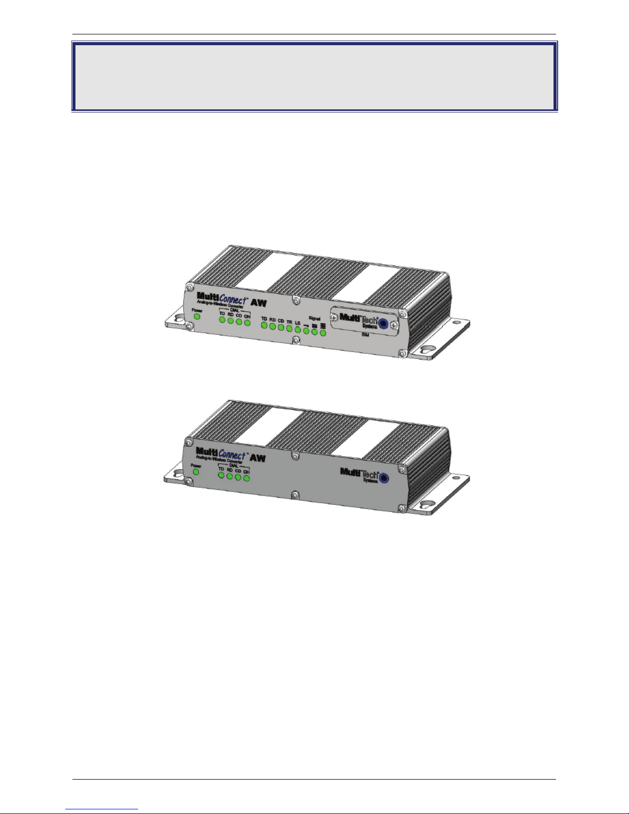
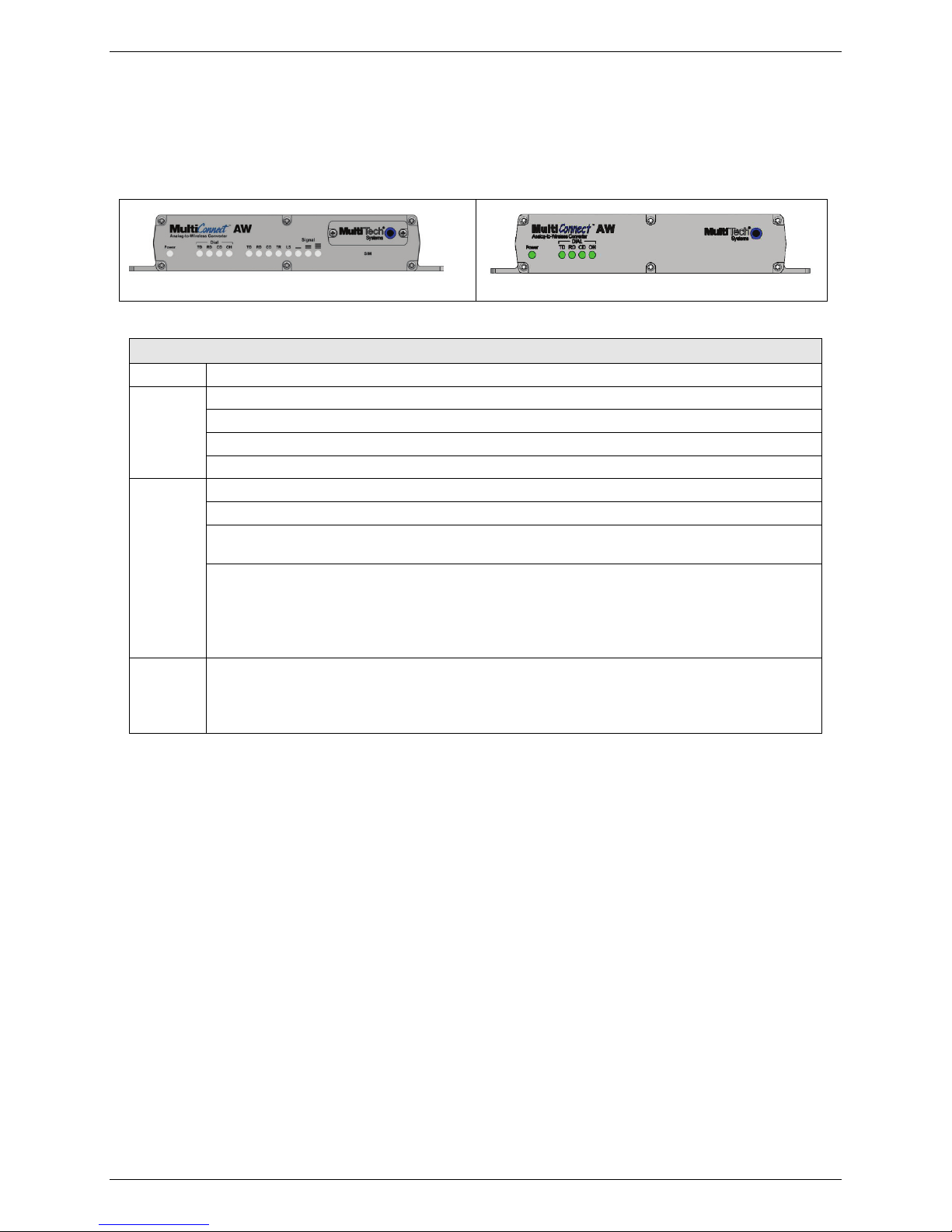
Front Panel .............................................................................................................................................. 6
Package Contents.................................................................................................................................... 6
Interfaces ................................................................................................................................................. 6
Specifications........................................................................................................................................... 7
RF Specifications ..................................................................................................................................... 9
Antenna Specifications ............................................................................................................................ 9
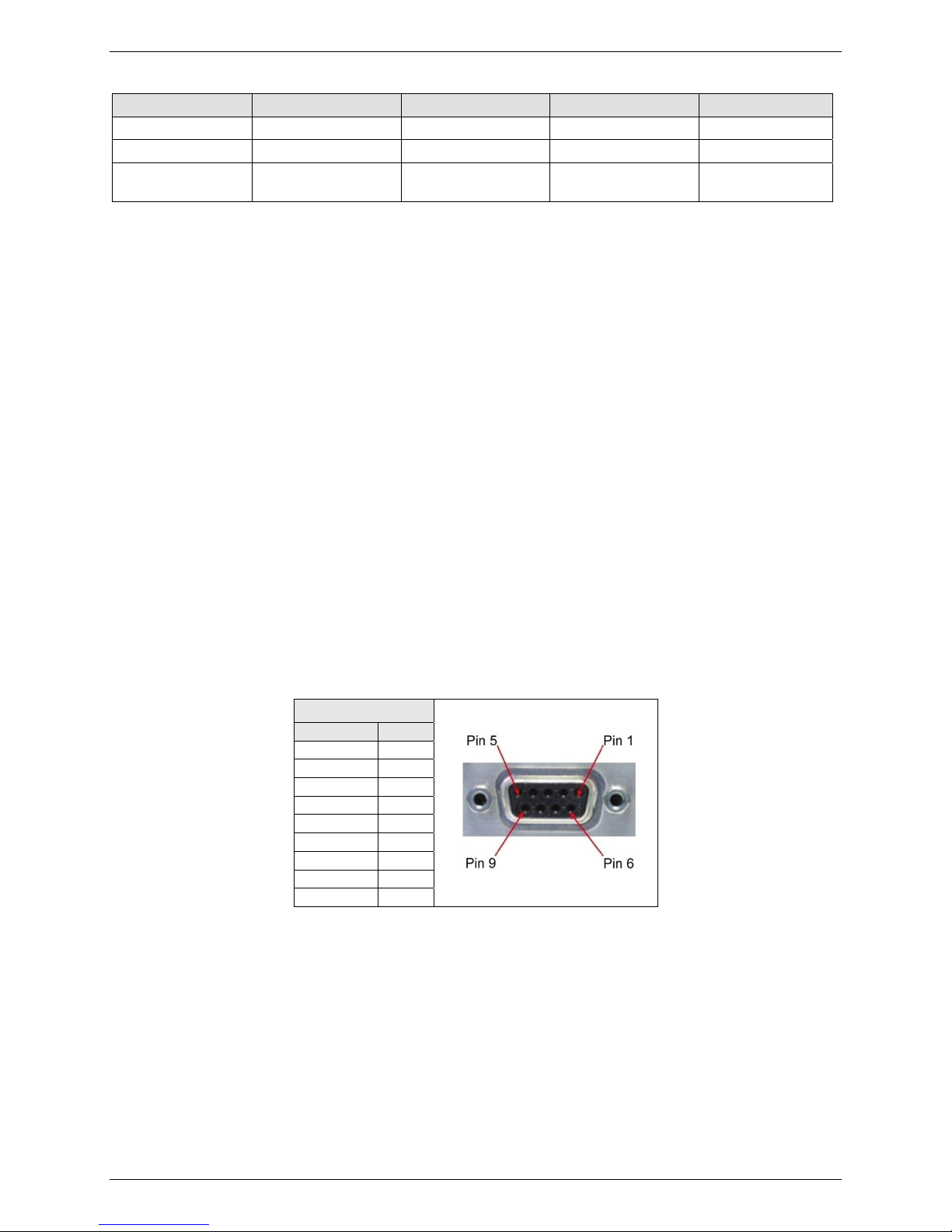
Modem Connector ................................................................................................................................... 9
CHAPTER 2 – ACTIVATION AND INSTALLATION .................................................................................10
Activate Your Wireless Account............................................................................................................. 10
Insert the SIM Card into Holder, if Required.......................................................................................... 10
Connect the Antenna, Serial Cable, Modem Cable, and Power............................................................ 11
Optional – Attach the Modem to a Flat Surface..................................................................................... 12
CHAPTER 3 - CONFIGURATION OF YOUR MULTICONNECT...............................................................13
Login ...................................................................................................................................................... 14
Device Configuration..............................................................................................................................15
Cellular Port Configuration..................................................................................................................... 16
CHAPTER 4 – DEVICE CONFIGURATION...............................................................................................19
GPRS Cellular Port Configuration ......................................................................................................... 20
GSM Cellular Port Configuration ........................................................................................................... 23
CDMA Cellular Port Configuration ......................................................................................................... 24
Analog (PSTN) Port Configuration......................................................................................................... 27
System Login ......................................................................................................................................... 29
Timers .................................................................................................................................................... 30
Setup Email............................................................................................................................................ 31
Reset Parameters to Default ................................................................................................................. 32
System Reboot ...................................................................................................................................... 33
APPENDIX A – REGULATORY COMPLIANCE........................................................................................34
EMC, Safety, and R&TTE Directive Compliance................................................................................... 34
International Modem Restrictions .......................................................................................................... 34
FCC Part 15 Class B Statement ............................................................................................................ 34
Industry Canada..................................................................................................................................... 34
APPENDIX B - WASTE ELECTRICAL AND ELECTRONIC EQUIPMENT (WEEE) STATEMENT.........35
APPENDIX C – ROHS HT/TS SUBSTANCE CONCENTRATION............................................................36

Chapter 1 – Product Description and Specifications
Multi-Tech Systems, Inc. MultiConnect AW User Guide 4
Chapter 1 – Product Description and
Specifications
Product Description
The MultiConnect™ AW analog-to-Wireless converter is a convenient turnkey solution that allows legacy
equipment with built-in analog modems to connect to a cellular network. By emulating the traditional dial-up PSTN
network and using a cellular modem, the affordable MultiConnect AW converter gives new life to devices currently
using traditional analog dial-up communications. The MultiConnect AW model (MT100A2W-G) with its internal GPRS
or GSM cellular modem allows connection to the cellular packet data network (GPRS) or the circuit switched data
network (GSM). The MultiConnect AW model (MT100A2W) requires a Multi-Tech CDMA, RS232 based external
modem for the cellular connection. Both models are housed in a rugged metal chassis. The MultiConnect AW
converter operates on standards based communication networks and can be desktop or panel mounted.
Model MT100A2W-G
Model MT100A2W
Features
●Turnkey solution with integrated quad-band GSM/GPRS modem, V.34/33.6K analog modem and SLIC for
PSTN emulation
●Supports GPRS packet data and circuit switched data modes
●RJ-11 port provides dial tone, ring, busy and DTMF detection
●Supports analog modem connections from 300 baud to 33.6K bps with error correction and data
compression
●Serial port configuration
●Rugged metal chassis
●LED’s for visual monitoring of power, signal strength, RS-232 and phone line status
●SMA antenna connector and SIM socket
●FCC, PTCRB and R&TTE certified
●Desktop or panel mounting
●Two-year warranty
60 .....
AT Command Information
AT commands for the MultiConnect AW are published in separate Reference Guides included on the
MultiConnect CD and posted on the Multi-Tech web site.

Chapter 1 – Product Description and Specifications
Multi-Tech Systems, Inc. MultiConnect AW User Guide 5
Safety
Dial Port Caution
The dial port is not designed to be connected to a Public Telecommunications Network (PSTN/phone line) or used
outside the building.
General Safety
The modem is designed for and intended to be used in fixed and mobile applications. “Fixed” means that the device
is physically secured at one location and is not able to be easily moved to another location. “Mobile” means that the
device is designed to be used in other than fixed locations.
Caution: Maintain a separation distance of at least 20 cm (8 inches) is normally maintained
between the transmitter’s antenna and the body of the user or nearby persons. The Modem
is not designed for or intended to be used in portable applications within 20 cm. (8 inches) of
the body of the user.
RF Interference Issues
It is important to follow any special regulations regarding the use of radio equipment due in particular to the possibility
of radio frequency, RF, interference. Please follow the safety advice given below carefully.
•Switch OFF your MultiConnect when in an aircraft. The use of cellular telephones in an aircraft may endanger
the operation of the aircraft, disrupt the cellular network and is illegal. Failure to observe this instruction may
lead to suspension or denial of cellular telephone services to the offender, or legal action or both.
•Switch OFF your MultiConnect when around gasoline or diesel-fuel pumps and before filling your vehicle with
fuel.
•Switch OFF your MultiConnect in hospitals and any other place where medical equipment may be in use.
•Respect restrictions on the use of radio equipment in fuel depots, chemical plants or where blasting operations
are in progress.
•There may be a hazard associated with the operation of your MultiConnect close to inadequately protected
personal medical devices such as hearing aids and pacemakers. Consult the manufacturers of the medical
device to determine if it is adequately protected.
•Operation of your MultiConnect close to other electronic equipment may also cause interference if the
equipment is inadequately protected. Observe any warning signs and manufacturers’ recommendations.
Maintenance of the Wireless MultiConnect
Your wireless MultiConnect is the product of advanced engineering, design, and craftsmanship and should be treated
with care. The suggestions below will help you to enjoy this product for many years.
●Do not expose the MultiConnect to any extreme environment where the temperature or humidity is high.
●Do not attempt to disassemble the MultiConnect. There are no user serviceable parts inside.
●Do not expose the MultiConnect to water, rain, or spilled beverages. It is not waterproof.
●Do not abuse your MultiConnect by dropping, knocking, or violently shaking it. Rough handling can damage it.
●Do not place the MultiConnect alongside computer discs, credit or travel cards, or other magnetic media. The
information contained on discs or cards may be affected by the phone.
●The use of accessories not authorized by Multi-Tech or not compliant with Multi-Tech’s accessory
specifications may invalidate the warranty of the MultiConnect.
●In the unlikely event of a fault in the MultiConnect, contact Multi-Tech Technical Support.
Handling Precautions
All devices must be handled with certain precautions to avoid damage due to the accumulation of static charge.
Although input protection circuitry has been incorporated into the devices to minimize the effect of this static build up,
proper precautions should be taken to avoid exposure to electrostatic discharge during handling and mounting.

Chapter 1 – Product Description and Specifications
Multi-Tech Systems, Inc. MultiConnect AW User Guide 6
Front Panel
The front panel is designed with a Power indicator and four Dial indicators on both models. The MT100A2W-G model
also has five wireless modem LEDs, three Signal strength LEDs, and a SIM door. The Power LED lights when power
is applied to the unit. The four analog signal LEDs (Dial) display the activity of the analog modem port. The five
wireless modem LEDs display the activity of the internal wireless modem and the three Signal strength LEDs display
the signal strength level of the internal wireless connection on the MT100A2W-G model. The SIM door on the right
side provides access to the SIM card holder for the MT100A2W-G model.
MT100A2W-G
MT100A2W
LEDs
LED Indicators
Power Indicates presence of DC power when lit.
Analog
Modem
Port
TD – Transmit Data – Flashes when the analog modem port is transmitting data.
RD – Receive Data – Flashes when the analog modem port is receiving data.
CD -Carrier Detect. Lit when the data connection from the analog modem port is established.
OH – Off-hook – Lit when the analog modem port goes off-hook
Internal
Wireless
Modem
TD – Transmit Data – Flashes when the wireless modem is transmitting data.
RD – Receive Data – Flashes when wireless modem is receiving data.
TR - Terminal Ready – Lit indicates the communication channel between the internal processor
and the internal wireless modem is ready.
LS - Link Status.
Off - Unit is off or not registered on network.
Continuous “ON” - Indicates that the wireless modem is not registered on the network.
Slow Flash * - Indicates registration on network.
Quick Flash ** – Indicates registration on the network and communication is in progress.
Signal ALL OFF - Unit is off, not registered on network, or extremely week signal (RSSI <7).
1 Bar “ON” – Very weak signal (7 < = RSSI <12)
1 Bar and 2 Bar “ON” – Week signal (12 < = RSSI <12)
1 Bar, 2 Bar, and 3 Bar “ON” – Good signal ( RSSI > = 15)
Package Contents
●1 MultiConnect Converter
●1 antenna
●1 RS232 cable
●1 power supply
●1 Quick Start Guide
●1 MultiConnect CD
Note: You must supply mounting screws.
Note: Your wireless provider will supply the SIM card.
Interfaces
The MultiConnect has several interfaces:
•LED function indicating operating status
•External antenna (via SMA connector)
•Serial port (Command) for configuration (via 9-pin DE9 female)
•Dial port (via RJ11)
•Modem port (via 9-pin DE9 male) (MT100A2W model only)
•Power supply (via 2.5mm miniature power jack)
•SIM card holder (MT100A2W-G model only)

Chapter 1 – Product Description and Specifications
Multi-Tech Systems, Inc. MultiConnect AW User Guide 7
Specifications
MT100A2W-G
Category Description
Performance GPRS; Class 10
Band, Frequency Quad-band, GSM/GPRS, 850/900/1800/1900M Hz
Packet Data Class 10, full PBCCH Support, coding schemes CS1-4, Mobile station Class B
Circuit-Switched Data Asynchronous, non-transparent up to 14.4Kbps (V.110)
Data Format For Serial Interface - Asynchronous, 8-N-1, Fixed 115K bps
Flow Control Hardware flow control
SIM Connector Standard 1.8V/3V SIM receptacle
Command Connector DE9 (female connector)
Dial Connector RJ11
Antenna Connector RF Antenna: SMA (female connector). Refer to Antenna Specifications.
Power Connector 2.5mm miniature screw-on
Voltage Range 9V to 32VDC @ 400mA
Power Requirements* Typical: 0.23A @ 9V @ 2.04W Max: 0.34A @ 9V @ 2.97W
0.12A @ 20V @ 2.31W 0.16A @ 20V @ 3.17W
0.08A @ 32V @ 2.48W 0.11A @ 32V @ 3.34W
9V Peak 1.43A
20V Peak 0.75A
32V Peak 0.50A
Dimensions 7” W x 1.24”H x 2.79”D .78lbs 17.78cmW x 3.15cmH x 7.07cmD 0.320Kg
Operating Temperature** -40° C to +60° C UL listed @ +40° C
Storage Temperature -40° C to +85° C
Humidity Relative humidity 20% to 90% noncondensing
Compliance EMC Compliance
FCC Part 15
EN55022
EN55024
Radio Compliance
FCC Part 22, 24
RSS 132,133
EN301 489-1
EN301 489-7
EN301 511
AS/ACIF S042.1, S042.3
Safety: UL60950-1
cUL60950-1
EN60950-1
Network Compliance: PTCRB, GCF
* Multi-Tech Systems, Inc recommends that the customer incorporate a 10% buffer into their power source when
determining product load.
** UL Listed @ 40°C. Limited by power supply. UL Certification does not apply or extend to an ambient above 40°C
and has not been evaluated by UL for ambient greater than 40°C
** “UL has evaluated this device for use in ordinary locations only. Installation in a vehicle or other outdoor locations
has not been evaluated by UL. UL Certification does not apply or extend to use in vehicles or outdoor applications or
in ambients above 40° C.”
** Optional power must be UL Listed ITE power supply marked LPS or Class 2 rated 9-32Vdc, 1.44 – 0.4A

Chapter 1 – Product Description and Specifications
Multi-Tech Systems, Inc. MultiConnect AW User Guide 8
MT100A2W
Category Description
Command Connector DE9 (female connector)
Modem Connector DE9
Dial Connector RJ11
Power Connector 2.5mm miniature screw-on
Voltage Range 9V to 32VDC @ 400mA
Power Requirements* Typical: 0.156A @ 9V @ 1.404W Max: 0.233A @ 9V @ 2.097W
0.078A @ 20V @ 1.560W 0.113A @ 20V @ 2.260W
0.053A @ 32V @ 1.696W 0.076A @ 32V @ 2.432W
Dimensions 7” W x 1.24”H x 2.79”D .70lbs 17.78cmW x 3.15cmH x 7.07cmD 0.318Kg
Operating Temperature** -40° C to +60° C UL listed @ +40° C
Storage Temperature -40° C to +85° C
Humidity Relative humidity 20% to 90% noncondensing
Compliance EMC Compliance
FCC Part 15
EN55022
EN55024
Safety: UL60950-1
cUL60950-1
EN60950-1
* Multi-Tech Systems, Inc recommends that the customer incorporate a 10% buffer into their power
source when determining product load.
** UL Listed @ 40°C. Limited by power supply. UL Certification does not apply or extend to an ambient above 40°C
and has not been evaluated by UL for ambient greater than 40°C
** “UL has evaluated this device for use in ordinary locations only. Installation in a vehicle or other outdoor locations
has not been evaluated by UL. UL Certification does not apply or extend to use in vehicles or outdoor applications or
in ambients above 40° C.”
** Optional power must be UL Listed ITE power supply marked LPS or Class 2 rated 9-32Vdc, 1.44 – 0.4A

Chapter 1 – Product Description and Specifications
RF Specifications
GSM 850 GSM 900 GSM 1800 GSM 1900
Frequency RX 869 to 894 MHz 925 to 960 MHz 1805 to 1800 MHz 1930 to 1990 MHz
Frequency TX 824 to 849 MHz 880 to 915 MHz 1710 to 1785 MHz 1850 to 1910 MHz
RF Power Stand 2W at 12.5% duty
cycle
2W at 12.5% duty
cycle
1W at 12.5% duty
cycle
1W at 12.5% duty
cycle
Antenna Specifications
GPRS/GSM Antenna Requirements/Specifications
Frequency Range: 824 – 960 MHz / 1710 – 1990 MHz
Impedance: 50 Ohms
VSWR: <2.0:1
Typical Radiated Gain: 3 dBi on azimuth plane
Radiation: Omni
Polarization: Vertical
Wave: Half Wave Dipole
Antennas Available from Multi-Tech Systems, Inc.
Description Part Number
Hinged Right Angle 900/1800 MHz Cellular Modem Antenna ANF1-1HRA
Hinged Right Angle 800/1900 MHz Cellular Modem Antenna ANF21HRA
Hinged Right Angle 850/900/1800/1900 MHz Cellular Modem Antenna ANQB-1HRA
PTCRB Requirements Note
There cannot be any alteration to the authorized antenna system. The antenna system must be the same type
with similar in-band and out-of-ban radiation patterns and maintain the same specifications.
FCC Requirements Note
The antenna gain, including cable loss, must not exceed 3.0 dBi at 1900 MHz / 1.4 dBi at 850 MHz for mobile
operating configurations and 7.0 dBi at 1900 MHz / 1.4 dBi at 850 MHz for fixed mounted operations, as defined
in 2.1091 and 1.1307 of the rules for satisfying RF exposure compliance.
Modem Connector
The following table explains the pin functions.
External Power Modem Connecto
r
(DE-9)
Signal IN/OUT
Pin 1 CD O
Pin 2 RX O
Pin 3 TX I
Pin 4 DTR I
Pin 5 GND --
Pin 6 DSR O
Pin 7 RTS I
Pin 8 CTS O
Pin 9 RI O
Multi-Tech Systems, Inc. MultiConnect AW User Guide 9

Chapter 2 – Activation and Installation
Chapter 2 – Activation and
Installation
Account Activation for Wireless Products
Please refer to the wireless account activation notice included with your unit and located on the MultiConnect CD.
Choose the one for your wireless network provider and follow the directions to activate your account.
Insert the SIM Card into Holder, if Required
The MultiConnect requires the power supply connection to begin operation. It also requires a SIM card (Subscriber
Identity Module) in the MT100A2W-G unit to operate on a GPRS/GSM network. To install the SIM, do the following:
1. Using a small Phillips screwdriver, remove the two SIM door screws and remove the SIM door.
Note: When changing a SIM, ensure that power is removed from the unit.
2. Insert the SIM card into the card holder. The above graphic illustrates the correct SIM card orientation.
3. Verify that the SIM card fits into the holder properly and then replace the cover.
Multi-Tech Systems, Inc. MultiConnect AW User Guide 10

Chapter 2 – Activation and Installation
Connect the Antenna, Serial Cable, Modem Cable, and
Power
MT100A2W-G
MT100A2W
1. Connect a suitable antenna to the ANT connector on the MT100A2W-G model, (see antenna specifications
in Chapter 1).
2. Connect the DE9 connector (9-pin) of the RS232 cable to the COMMAND connector on the unit and connect
the other end to serial port on your PC.
3. For the MT100A2W model, connect an RS232 cable, male connector, to the MODEM connector on the back
of the unit. Connect the other end of the cable to your external wireless modem.
4. Connect the RJ 11 phone cable to the DIAL connector on the unit and connect the other end of the phone
cable to the customer’ s analog modem.
5. Remove the protective shipping cover. Attach the appropriate input connector to the power supply module
by holding down on the slide lock and tipping the input connector to fit into the notch on top of the module
and then lowering it into the slide lock. Then release the slide lock.
6. Screw-on the power lead from the power supply module to the power connection on the unit. Now, plug the
power supply into your power source.
Multi-Tech Systems, Inc. MultiConnect AW User Guide 11

Chapter 2 – Activation and Installation
Optional – Attach the Modem to a Flat Surface
The modem can be panel mounted with screws spaced according to the measurement shown.
Note: Use either #4 or #6 pan head screws for all four mount locations.
Multi-Tech Systems, Inc. MultiConnect AW User Guide 12

Chapter 3 – Configuration of your MultiConnect
Chapter 3 - Configuration of your
MultiConnect
The configuration of the MultiConnect varies slightly depending on which unit you are configuring, MT100A2W-G
which has the internal GPRS/GSM wireless modem. The MT100A2W requires a Multi-Tech CDMA, RS232 based
external modem for its cellular connection. The Cellular Port configuration for the MT100A2W-G has more
configuration options than the MT100A2W unit. The differences are detailed in the Cellular Port Configuration.
The following configuration procedures are based on the Windows XP Operating System. Other Windows operating
systems have similar paths to HyperTerminal. See your system’s online Help if you cannot find it.
HyperTerminal
1. Go to Start I All Programs I Accessories I Communications and then click on HyperTerminal.
2. The New Connection screen is displayed. In the Name: window, enter an applicable name for your
MultiConnect connection.
Click OK.
3. The Connect To screen is displayed with the Country/region, Area code, and phone number windows
blanked out.
Multi-Tech Systems, Inc. MultiConnect AW User Guide 13
Change the Connect using: window to the COM port for the MultiConnect. Click on the down arrow and
select your COM port.

Chapter 3 – Configuration of your MultiConnect
4. The COM Properties screen is displayed.
Change the default Bits per second: window from 2400 to 115200. Click the Apply button and then OK.
Login
1. The Login screen is displayed.
Enter the default password of admin
Multi-Tech Systems, Inc. MultiConnect AW User Guide 14

Chapter 3 – Configuration of your MultiConnect
2. What would you like this port to do? Screen is displayed.
Enter Selection => _ Enter A and press OK
Device Configuration
Initial configuration of the MultiConnect AW could involve just the Cellular Port menu which is dependent on cellular
network that you are connecting to. The Device Configuration main menu changes depending on the cellular network.
The cellular network change is in Option 1 which in the Current Settings displays the cellular network type; GPRS or
GSM for the MT100A2W-G unit or CDMA for the MT100A2W unit. The GPRS cellular network is for packet switched
data. GSM uses circuit switch data.
The Analog (PSTN) Port menu is defaulted to a typical configuration. The System Login option thru the System
Reboot options refine the use of your MultiConnect AW.
1. The Device Configuration main menu is displayed.
Multi-Tech Systems, Inc. MultiConnect AW User Guide 15
In the Enter option to modify => _ Enter 1and press OK for both versions. The Cellular Port configuration
menu is displayed.

Chapter 3 – Configuration of your MultiConnect
Cellular Port Configuration
The Cellular Port configuration is dependent on the cellular network, a GPRS Cellular network is the default cellular
network for MT100A2W-G units and contains the most options to configure. When the Cellular Port is set to GSM on
the MT100A2W-G units, the number of configuration options are reduced. When a MT100A2W unit determines that
there is no internal wireless modem, the Device Configuration menu changes to a CDMA network.
The GPRS Cellular network configuration is detailed in the following section. The GSM Cellular Network
configuration is detailed in the next section, and finally the CDMA Cellular network configuration is detailed in the last
section of the Cellular Port Configuration.
GPRS Cellular Network Configuration
1. The GPRS Cellular Port menu is displayed.
2. Configure options A thru D for your GPRS cellular network.
GPRS Network Dependent
Option Default Description
A) GPRS or GSM GPRS Select GPRS
B) Protocol TCPClient Select either TCPClient, Telnet, UDP, or
Pass Thru
C) Inbound or
Outbound Outbound Select either
0) Auto Detect which automatically
detects between inbound and outbound,
1) PPP Client (Outbound),
2) PPP Client (Listening) for inbound.
D) Wireless
Connection OnDemand Select either OnDemand or Always On.
ATTENTION: If Always On is desired,
wait until you have made all your other
configuration changes before selecting
this option.
3. When you change the Remote Port or Remote IP, they become the new default without pressing the + key
to save the configuration.
Multi-Tech Systems, Inc. MultiConnect AW User Guide 16
Port Dependent
Option Default Description
E) Local Port 23 The Local Port is for inbound
communications
F) Remote Port 0 TCP/IP port that remote device is
listening on.
G) Remote IP None IP address of remote device on the
network you are connecting to.

Chapter 3 – Configuration of your MultiConnect
4. The Wireless Band is set depending on the region of the world the unit is set up for, e.g., 850/1900MHz for
NAM.
Wireless Band
Option Default Selection
K) Wireless Band This option is default depending on the region of the
world the unit is set up for, e.g., 900/1800MHz for
Europe.
0) dual-band 850/1900 MHz
1) dual-band 900/1800 MHz
5. Configure options L thru N dependent on your Access Point Name (APN) Server requirements.
APN Dependent
Option Default Selection
L) APN User Name The user name may not be required by all network
providers.
M) APN Password The password may not be required by all network
providers.
N) APN Server The APN assigned by your cellular network provider.
6. Save your configuration by pressing the + key. Then return to the Main Device Configuration menu and wait
for the cellular wireless network and the analog modem to change to a READY state. The Current Settings
will change to: (State WIRELESS_READY) (State ANALOG_READY).
Initial configuration of the GPRS version is complete.
GSM Cellular Network Configuration
1. The GSM Cellular Port menu is displayed.
2. Configure options A thru D for your GSM cellular network.
GSM network Dependent
Option Default Selection
A) GPRS or GSM GPRS Select GSM
B) Protocol PassThru No selection
K) Wireless Band This option is default depending on the region of the world
the unit is set up for, e.g., 850/1900MHz for NAM.
0) dual-band 850/1900 MHz
1) dual-band 900/1800 MHz
Multi-Tech Systems, Inc. MultiConnect AW User Guide 17
3. You need to save your configuration by pressing the + key. Then return to the Main Device Configuration
menu and wait for the cellular wireless network and the analog modem to change to a READY state. The
Current Settings will change to: (State WIRELESS_READY) (State ANALOG_READY).
Initial configuration of the GSM version is complete.

Chapter 3 – Configuration of your MultiConnect
CDMA Cellular Network Configuration
When an external Multi-Tech CDMA modem is connected to the MODEM port of a MT100A2W unit and the unit is
powered up, the Device Configuration menus will default to a CDMA Cellular Network.
1. The CDMA Cellular Port menu is displayed.
2. Configure options A thru D depending on your CDMA cellular network.
CDMA Network Dependent
Option Default Description
A) CDMA CDMA No selection
B) Protocol TCPClient Select either TCPClient, Telnet, UDP,
or Pass Thru
C) Inbound or
Outbound Outbound Select either
0) Auto Detect which automatically
detects between inbound and outbound,
1) PPP Client (Outbound),
2) PPP Client Inbound (Listening).
D) Wireless
Connection OnDemand Select either OnDemand or Always On
ATTENTION: If Always On is desired,
wait until you have made all your other
configuration changes before selecting
this option.
3. When you change the Remote Port or Remote IP, they become the new default without pressing the + key
to save the configuration.
Port Dependent
Option Default Description
E) Local Port 23 The Local Port is for inbound
communications
F) Remote Port 0 TCP/IP port that remote device is
listening on.
G) Remote IP None IP address of remote device on the
network you are connecting to.
Multi-Tech Systems, Inc. MultiConnect AW User Guide 18
4. You need to save your configuration by pressing the + key. Then return to the Main Device Configuration
menu and wait for the cellular wireless network and the analog modem to change to a READY state. The
Current Settings will change to: (State WIRELESS_READY) (State ANALOG_READY).
Initial configuration of the CDMA Version is complete.

Chapter 4 – Device Configuration
Multi-Tech Systems, Inc. MultiConnect AW User Guide 19
Chapter 4 – Device Configuration
The Device Configuration menu displays seven main menu options and navigational selections such as Main Menu,
Save & Exit, etc. The numbered options are the configurable options and the alphabetical options are the navigational
selections. The Enter option to modify => at the bottom of the menu is your selection field.
Each numbered option in the Device Configuration menu has its own sub-menu with the individual settings for that
option. You can select option 1) Cellular Port and press ENTER. The Cellular Port menu is displayed. You can now
select a setting, modify it, and then save and exit.
1) Cellular Port
GPRS Cellular Port * GSM Cellular Port * CDMA Cellular Port **
A) GPRS B) Protocol
C) Inbound/Outbound D) Wireless Connection
E) Local Port F) Remote Port
G) Remote IP
J) View or change Phone Number/IP Conversion
Table K) Wireless Band
L) APN User Name M) APN Password
N) APN Server O) Phy TimeOut (Min)
P) DLE Mode Q) TCP TxDelay
R) HandShake TimeOut (sec)
Z) Enter Wireless Modem Command Mode
A) GSM B) Protocol
K) Wireless Band
R) HandShake TimeOut (sec)
Z) Enter Wireless Modem Command
Mode
A) CDMA B) Protocol
C) Inbound/Outbound
D) Wireless Connection
E) Local Port F) Remote Port
G) Remote IP
J) View or change Phone
Number/IP Conversion Table
Z) Enter Wireless Modem
Command Mode
2) Analog (PSTN) Port 3) System Login 4) Timers
A) Modem Initilazition String
B) Modem Settings A) No Login
B) Login Required
C) Change Password
A) Menu Inactivity Timer
B) No Signal Reset Timer (Not
applicable to CDMA)
5) Set Email 6) Reset Parameters to
Default 7)System Reboot
A) SMTP UN B) SMTP PW
C) SMTP PORT D) SMTP Authentication
E) SMTP Server F) Domain
G) Sender’s Name H) Sender’s Address
I) Recipient’s Address
Are you sure you want to reset ALL
parameters back to Defaults?
yes/no
Are you sure you want to reboot the
unit?
Yes/no
Note: * MT100A2W-G only.
** MT100A2W only.

Chapter 4 – Device Configuration
GPRS Cellular Port Configuration
Multi-Tech Systems, Inc. MultiConnect AW User Guide 20
Network Dependent
Option Default Description
A) GPRS or GSM GPRS The GPRS or GSM option is based on the SIM
installed in the unit.
1) GPRS option requires a packet switched cellular
network.
B) Protocol TCP Client 1) TCP Client option is an internet protocol intended
to get data from one network device to another.
2) Telnet option is a client communication.
3) UDP option is a connectionless protocol in that
UDP makes no provision for acknowledgement of
packets received.
4) PassThru option allows for data to be transferred
from a legacy device to a remote destination without
being modified.
C) Inbound/Outbound Outbound 0) Auto Detect automatically detects between
inbound and outbound.
1) PPP Client (Outbound) option is for outbound
traffic from the MultiConnect AW to the wireless
network.
2) PPP Client Inbound (Listening) option is for
inbound traffic to the MultiConnect AW
D) Wireless Connection OnDemand 1) On-Demand option initiates the wireless
connection when a request made.
2) Always On option is always connected to the
cellular network.
ATTENTION: If Always On is desired, wait until you
have made all your other configuration changes
before selecting this option.
This manual suits for next models
1
Table of contents
Other Multitech Media Converter manuals