3
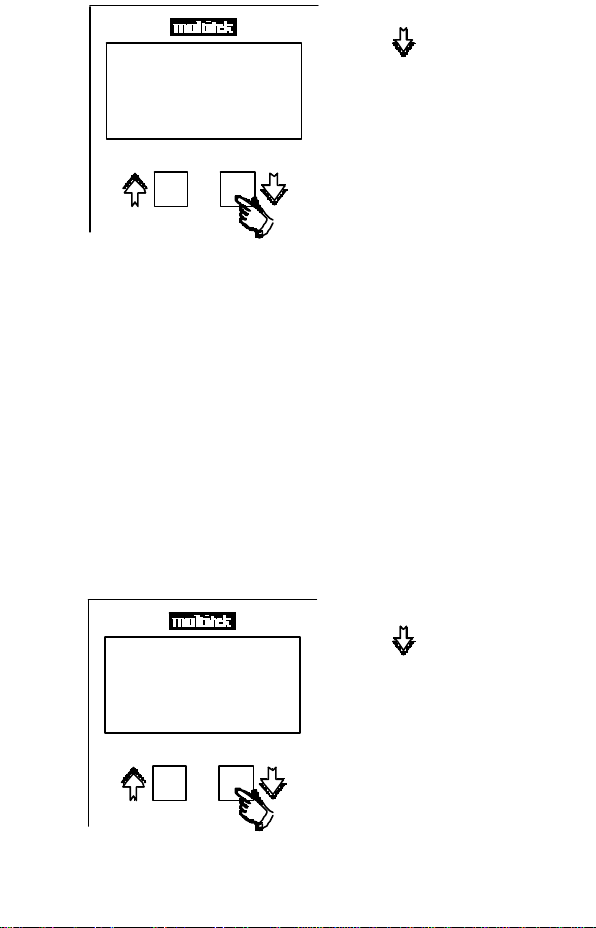
The MultiGen is designed to be user friendly and simple to
use. All operations are controlled by the two push buttons
& on the front of the M8**.
All necessary programming is also carried out via the front
two control buttons. The MultiGen units are fully
programmed by the factory and no further programming is
necessary. If required, the User can reprogram
parameters to individual requirements, such as the nominal
current and voltage inputs, relay output etc. These
programming operations are covered in this manual (see
section 4).
The MultiGen uses a high speed microprocessor and
analogue to digital conversion circuitry. Phase voltage and
current measurements are true RMS and the coolant and
oil pressure are measured directly from the engine sender.
Hours Run is measured from the frequency, and DC volts
measured directly from the battery.
1.1 General
The MultiGen M820-GM* series & M830-SM* series are
compact 96 x 96 mm Din case 3 phase generator
monitoring meters, The M820-GM* series measure Volts,
Amps, Frequency, Coolant Temperature, Pressure, Hours
Run, DC volts, and provide relay outputs for temperature
and pressure. The M830-SM series measure Volts Amps
and Frequency.
Power Systems :- Product code
1 Ph. M820-GM1 or M830-SM1
3 Ph. 3W unbalanced load M820-GM4 or M830-SM4
3 Ph. 4W unbalanced load M820-GM9 or M830-SM9
GENMOM.PM5 20/03/100, 10:323